Page is loading ...

HOT WATER MODELS VHS-30 THROUGH VHS-180
GAS-FIRED CAST-IRON BOILERS FOR NATURAL AND L.P. PROPANE GASES
The installation must conform to the requirements of the
authority having jurisdiction or, in the absence of such
requirements, to the National Fuel Gas Code, ANSI Z223.1-
latest edition. The installation must also conform to the addi-
tional requirements in this Slant/Fin Instruction Book.
In addition where required by the authority having jurisdic-
tion, the installation must conform to American Society of
Mechanical Engineers Safety Code for Controls and Safety
Devices for Automatically Fired Boilers, No. CSD-1.
WARNING
This boiler, gas piping and accessories must be installed,
connected, serviced and repaired by a trained, experienced
service technician, familiar with all precautions required for
gas-fired equipment and licensed or otherwise qualified, in
compliance with the authority having jurisdiction.
WARNING
The venting system of this boiler is under positive pressure
when it is connected to the outdoors with 3" diameter pipe.
Leakage from this system can be hazardous and if not avoid-
ed can result in death or serious injury. In addition to the rec-
ommendations within this manual and the User’s Information
Manual, the venting system, from the blower to the outdoor
discharge, must be carefully checked annually by a qualified
service agency.
This manual must be left with owner and
should be hung on or adjacent to the boiler
for reference.
VICTORY II
™
Models with Intermittent Pilot System – Spark Ignition
INSTALLATION AND OPERATING INSTRUCTIONS
Publication No. VHS-41 Rev.C Part No. 44-0849 Printed 1019
Heating Contractor
Address
Phone Number
Boiler Model Number
Boiler Serial Number
Installation Date
Contents . . . . . . . . . . . . . . . . . . . . . . . . . . . . . . . . . . . . . .Page
Dimensions, Rating and Orifice Sizes . . . . . . . . . . . . . . . . . . .2
Installation Requirements:
Boiler Location and Foundation . . . . . . . . . . . . . . . . . . . . .3
Minimum Clearances . . . . . . . . . . . . . . . . . . . . . . . . . . . . .3
Boiler Room Air Supply and Ventilation . . . . . . . . . . . . . . .4
Flue Gas Venting Requirements . . . . . . . . . . . . . . . . . . . . . . .4
Category II and III Venting:
Venting Material . . . . . . . . . . . . . . . . . . . . . . . . . . . . . . . . .5
Flue Length Restriction . . . . . . . . . . . . . . . . . . . . . . . . . . .5
Installation . . . . . . . . . . . . . . . . . . . . . . . . . . . . . . . . . . . . .5
Category I Venting:
Installation . . . . . . . . . . . . . . . . . . . . . . . . . . . . . . . . . . . .10
Vent Connector Material . . . . . . . . . . . . . . . . . . . . . . . . . . . .10
Venting Requirements . . . . . . . . . . . . . . . . . . . . . . . . . . .10
Venting System Regular Inspection . . . . . . . . . . . . . . . . . . . .14
Gas Piping . . . . . . . . . . . . . . . . . . . . . . . . . . . . . . . . . . . . . . .14
Electrical Wiring . . . . . . . . . . . . . . . . . . . . . . . . . . . . . . . . . . .14
Boiler Water Temperature Control . . . . . . . . . . . . . . . . . .19-23
Water Piping . . . . . . . . . . . . . . . . . . . . . . . . . . . . . . . . . . . . . .26
Piping a Heating-Cooling System . . . . . . . . . . . . . . . . . . . . .26
Operating Instructions:
Filling and Venting Water Systems . . . . . . . . . . . . . . . . .27
Initial Start . . . . . . . . . . . . . . . . . . . . . . . . . . . . . . . . . . . .27
Safety Information . . . . . . . . . . . . . . . . . . . . . . . . . . . . . .27
Operating Instruction . . . . . . . . . . . . . . . . . . . . . . . . . . . .27
Burner Adjustment . . . . . . . . . . . . . . . . . . . . . . . . . . . . . . . . .27
Safety Check . . . . . . . . . . . . . . . . . . . . . . . . . . . . . . . . . . . . .28
Care and Maintenance . . . . . . . . . . . . . . . . . . . . . . . . . . . . . .29
Sequence of Operations . . . . . . . . . . . . . . . . . . . . . . . . . . . .31
General Troubleshooting Guide . . . . . . . . . . . . . . . . . . . . . . .32
Appendix A and B . . . . . . . . . . . . . . . . . . . . . . . . . . . . . . . . . .34
WARNING
SEE “WARNING” ON PAGE 3 FOR LIQUEFIED
PETROLEUM (L.P.) PROPANE GAS-FIRED BOILERS
IMPORTANT
READ ALL OF THE FOLLOWING WARNINGS
AND STATEMENTS BEFORE READING THE
INSTALLATION INSTRUCTIONS
CANADIAN ENERGY
PERFORMANCE
VERIFIED
RENDEMENT
ENERGETIQUE
VERIFIE

VICTORY II VHS Models
2
NOTE: Height dimensions increase by 1
3
⁄4" and depth increases to 22
1
⁄4" when combustible floor kit is used.
Natural #49 50 50 50 51 51 51 52 52 52
Propane #57 58 59 59 60 60 61 62 63 63
VHS-30EP 30,000 2 8
1
⁄8" 14
5
⁄8" 190
VHS-60EP 60,000 3 11
1
⁄8" 17
5
⁄8" 250
VHS-90EP 90,000 4 14
1
⁄8" 20
5
⁄8" 310
VHS-120EP 120,000 5 17
1
⁄8" 23
5
⁄8" 365
VHS-150EP 150,000 6 20
1
⁄8" 26
5
⁄8" 425
VHS-180EP 180,000 7 23
1
⁄8" 29
5
⁄8" 485
Boiler
Model
No. of
Sections
Input
Btuh
A
B
Approx.
Total Wt.
Full of
Water (lb.)
Gas
Type
2000 3000 4000 5000 6000 7000 8000 9000 10000
Orifice
Size for
Sea Level
Orifice Sizes for High Altitudes
Includes 4% Reduction for Each 1000 Feet
Elevation — Feet
Orifice sizes indicated for sea level above are factory installed in boiler unless otherwise specified
by the local authority. Orifice table is based on a higher heating value between 1000 Btuh and
1010 Btuh for Natural Gas (See page 21, if local higher heating value exceeds these numbers).
See page 21, for burner input adjustment.
LEFT END VIEW FRONT VIEW RIGHT END VIEW
Figure 1. Views - Dimensions - Data
Figure 2. Base Assembly Victory II - VHS Boiler
Gas manifold
Burners
Pilot
Burner
access door
Gas valve

VICTORY II VHS Models
3
INSTALLATION REQUIREMENTS
The installation must conform to the requirements of the
authority having jurisdiction or, in the absence of such
requirements, to the National Fuel Gas Code, ANSI Z223.1-
latest edition.
This installation must also conform to the additional require-
ments in this Slant/Fin Instruction Book.
NATURAL GAS-FIRED BOILER LOCATION
Provide a level, solid foundation for the boiler. Location
should be as near as possible to chimney or outside wall so
that the flue pipe from boiler is short and direct. (See Appen-
dix A for vent terminal location restrictions.) The location
should also be such that the gas ignition system components
are protected from water (dripping, spraying, rain, etc.) during
appliance operation and service (circulator replacement, con-
densate trap, control replacement, etc.).
WARNING
SPECIAL ATTENTION FOR LIQUEFIED PETROLEUM
(L.P.) PROPANE GAS-FIRED BOILER INSTALLATIONS
LPG appliances (boilers) shall be installed in accordance
with applicable provisions of NFPA 58 ( Liquefied Petroleum
Gas Code) latest edition for installations in US and
CAN/CGA B149.1 latest edition for installations in Canada.
Liquefied Petroleum (LP) propane gas is heavier than air there-
fore Propane gas accumulate at floor level. If you suspect a
leak, do not attempt to operate boiler. A spark or flame from the
appliance (boiler) or other sources may ignite the accumulated
propane gas causing an explosion or fire. It is recommended
that inspections for gas leaks be performed periodically by
licensed professional and that leak detection devices be
installed as a further safety measure.
BOILER FOUNDATION
A. Provide a solid, level foundation, capable of supporting
the weight of the boiler filled with water, and extending at
least 2" past the jacket on all sides. See dimensions of
boilers, page 2.
B. For installation on non-combustible floors only*.
C. If boiler is to be located over buried conduit containing
electric wires or telephone cables, consult local codes or
the National Board of Fire Underwriters for specific
requirements.
* Installation on combustible flooring allowed only with proper Com-
bustible Floor Kit. Kit part number is printed on boiler rating plate.
In no case may the boiler be installed on carpeting.
MINIMUM CLEARANCES FROM COMBUSTIBLE
CONSTRUCTIONS
A. Minimum clearances to the exterior surfaces of the boiler
shall be as follows:
MINIMUM ALCOVE AND CLOSET CLEARANCE
For Combustible Recommended
Surface Construction for Service
Front 6" 18"
Rear 6" 18"
Left Side 6" 18"
Right Side 12" 24"
Top 12" 12"
Flue Connector:
Enclosed — 6" 6"
Unenclosed — 2" 6"
B. Provide accessibility clearance of 24" on sides requiring
servicing and 18" on sides used for passage.
C. All minimum clearances shown above must be met. This
may result in increased values of some minimum clear-
ances in order to maintain the minimum clearances of
others.
D. Clearance from hot water pipes shall be 1 inch**.
** At points where hot water pipes emerge from a floor, wall or ceiling,
the clearance at the opening through the finished floor boards or wall
or ceiling boards may be not less than 1/2 inch. Each such opening
shall be covered with a plate of uncombustible material.
SAFETY
KEEP THE BOILER AREA CLEAR AND FREE FROM
COMBUSTIBLE MATERIALS, GASOLINE AND OTHER
FLAMMABLE VAPORS AND LIQUIDS.
Figure 3.

VICTORY II VHS Models
4
BOILER ROOM AIR SUPPLY AND VENTILATION
An ample supply of air is required for combustion and venti-
lation. When buildings are insulated, caulked and weather-
stripped, now or later on, direct openings to outside may be
required and should be provided. If the boiler is not near an
outside wall, air may be ducted to it from outside wall open-
ings.
Provisions for combustion and ventilation air must be made
in accordance with section 5.3, Air for Combustion and Venti-
lation, of the National Fuel Gas Code, ANSI Z223.1-latest
edition, or applicable provisions of the local building codes.
The following recommendation applies to buildings of ener-
gy-saving construction, fully caulked and weatherstripped.
INSTALLATION IN ENCLOSED BOILER ROOM REQUIRES
TWO UNOBSTRUCTED OPENINGS FOR PASSAGE OF
AIR INTO THE BOILER ROOM:
1. Air drawn horizontally from outdoors DIRECTLY
through an outside wall; one louvered opening near
the floor and one louvered opening near the ceiling, each
opening with a minimum FREE air passage area of 1
square inch per 4000 Btuh of total appliances’ input.
2. Air drawn horizontally through HORIZONTAL
DUCTS; one opening near the floor and one opening
near the ceiling, each opening with a minimum FREE air
passage area of 1 square inch per 2000 Btuh of total
appliances’ input.
3. Air drawn VERTICALLY from outdoors; one opening
at the floor and one opening at the ceiling, each opening
with a minimum FREE air passage area of 1 square
inch per 4000 Btuh of total appliances’ input.
4. Air drawn from inside the building; one opening near
the floor and one opening near the ceiling, each opening
with a minimum FREE air passage area of 1 square
inch per 1000 Btuh of total appliances’ input.
IF BOILERS ARE INSTALLED ADJACENT TO OTHER
FUEL BURNING EQUIPMENT, THE AREA OF FREE OPEN-
INGS MUST BE APPROPRIATELY INCREASED TO
ACCOMMODATE THE ADDITIONAL LOAD.
Openings must never be reduced or closed. If doors or win-
dows are used for air supply, they must be locked open. Pro-
tect against closure of openings by snow and debris.
Inspect frequently.
No mechanical draft exhaust or supply fans are to be used in
or near the boiler area.
The flow of combustion and ventilating air to the boiler must
not be obstructed.
FLUE GAS VENTING REQUIREMENTS
The Victory II series boiler is a high efficiency, mechanically
induced draft boiler and, therefore, requires different venting
arrangements than natural draft, lower efficiency boilers.
THE FOLLOWING INSTRUCTIONS MUST BE CAREFULLY
READ AND FOLLOWED IN ORDER TO AVOID ANY HAZ-
ARDOUS CONDITIONS DUE TO IMPROPER INSTALLA-
TION OF THE FLUE GAS VENTING SYSTEM.
The vent piping installation MUST be in accordance with
these instructions and with ANSI Z223.1-latest edition
NATIONAL FUEL GAS CODE, Part 7, Venting of Equipment.
Other local codes may also apply and must be followed.
Where there is a conflict between these requirements, the
more stringent case shall apply.
The use of a vent damper or similar devices is NOT permit-
ted on this boiler series.
Approved Venting Applications
Victory II model VHS-90 through 180 are Category III and
VHS-30 and 60 are Category II boilers, these boilers must
be vented by proper 3" diameter venting system (see Cate-
gory II and III venting - page 5).
Models VHS-90 through 180 are also Category I boilers
when using a minimum of 5" diameter connector and vented
into a natural draft chimney or Type “B” vent using a 3"x5"
diameter vent adapter (see Category I venting - page 9).

VICTORY II VHS Models
5
CATEGORY II AND III VENTING
1. Vent Material
A) The vent system for horizontal or vertical venting
(Category II and III) must be UL listed single wall 3"
diameter AL29-4C
▲
stainless steel material. The follow-
ing manufacturers’ systems are approved for use within
a specified minimum and maximum equivalent vent
length for each model. Proper adapter must be used as
a connector between Victory II boilers flue collar and
venting system as shown below:
Heat-Fab Part Numbers for various items of vent system are
listed in Slant/Fin Part List, Publication No. VHS-10PL.
B) When joining the various components of the above
listed vent systems, the manufacturers’ instructions
should be closely followed to insure proper sealing.
C) Use sealant specified by vent system manufacturer
for sealing of pipe and fittings. See Figure 4 for
proper application of vent pipe sealing for Safe-T vent
system by Heat-Fab. Inc.
D) All vent connections must be liquid and pressure tight
E) Flue vent system CANNOT be cut to length. Consult
manufacturer’s instructions. For Heat-Fab system, use
slip joint connector (Part No. 7324-GC) to adjust pipe
lengths dimensions.
F) DO NOT use plastic or galvanized flue pipe.
2. Flue Length Restriction
Maximum and minimum equivalent flue length for different
systems are given in the tables on page 6. Equivalent flue
length is sum of straight flue lengths and equivalent
length of elbows. The vent termination is in addition to the
allowed equivalent lengths.
Example: Boiler Model VHS-180 is to be installed at sea
level with 2 elbows using Heat-Fab vent system. Maximum
straight run would be: 40 - 2 x 3 = 34ft. If same boiler is to
be installed in Colorado Springs (5,980 ft. altitude), the maxi-
mum straight run would be: 20 - 2 x 3 = 14 ft.
3. Installation
A. Horizontal Venting:
Figures 5 and 6 show typical horizontal venting. For com-
bustible wall passage of vent piping a U.L. listed thimble
must be used. See Figures 5 and 6 for wall thimble Part
Numbers and more information.
CAUTION: Flue gasses exiting from the vent terminal will
condense. Building materials in the area of the vent terminal
should be protected from discoloration and degradation.
VENT TERMINATION LOCATION AND CLEARANCES
1. The venting system shall terminate at least 3 feet above any
forced air inlet located within 10 feet.
2. The venting system shall terminate at least 12 inches below, or
12 inches horizontally from, any door, window or gravity air inlet
into any building. The bottom of the vent terminal shall be at
least 12 inches above grade or the normal snow leve
whichever is greater.
3. Through the wall vents shall not terminate over public
walkways or over areas where condensate or vapor could
create a nuisance or hazard or could be detrimental to the
operation of regulators, relief valves or other equipment.
Minimum clerance of 4 feet horizontal distance is maintained,
from electric meters, gas meters, regulators and relief
equipment.
4. Vent termination must not be located in any confined space (i.e.
window wells, alcoves, narrow alleys) or under anyoverhang or
deck. Vent termination should not allow flue gas discharge
towards neighbor’s windows or where personal injury or
property damages can occur.
B. Vertical Venting:
Figure 7 shows typical vertical venting. A fire stop is required for
each ceiling and floor penetration. An existing chimney (see Fig-
ure 8) may be used as a chase for vertical venting. Other appli-
ances CANNOT be vented into the same chimney or vent pipe
within the chimney.
For both, horizontal and vertical venting, the following points
MUST be followed:
A. All Victory II boilers are equipped with a built-in condensation
drain and trap. The trap loop must be filled with water. DO NOT
operate the boiler without filling the trap with water to prevent
flue gas discharge into space. The drain should extend to a floor
drain or to a container which may require emptying periodically.
B. The horizontal vent pipe must be sloped upward from the boiler
at a pitch of at least 1/4" per 1 foot of run, so that the conden-
sate from the vent system runs to the drain trap.
C. The horizontal vent pipes must be supported with pipe straps at
intervals no greater than indicated by vent pipe manufacturer’s
instructions. The vertical portion vent pipe also must be support-
ed per manufacturer’s instructions.
D. Minimum clearances of vent pipes from combustible construc-
tions must be maintained (see Page 3).
E. Common venting with other appliances or another Victory II boil-
er is NOT allowed.
F. The vent piping must terminate with a screened elbow or tee.
See Figures 5 and 6 for horizontal and 7 and 8 for vertical termi-
nation information. A cap termination may be used for vertical
venting.
G. See Appendix A for vent system location and condensation drain
requirements.
H. For roof passage of vent piping a U.L. listed roof flashing
must be used.
▲
: AL 29-4C is a registered trademark of Allegheny Ludlum Corp.
Figure 4. Vent Sealing Instructions
(Consult vent manufacturer’s instructions.)
Manufacturer Type/System
Adapter Part
No. Sealant
Heat-Fab. Inc. Saf-T Vent Not Required
RTV 106 or DOW
Coming 732
Heat-Fab. Inc.
Saf-T Vent
EZ Seal
Not Required Not Required
Pro-Tech
System, Inc.
FasNSeal FSA-HFA3 Not Required
Flex-L
International, Inc
StaR-34 SRAFSA3 GE-1S806
Z-Flex, Inc. Z-Vent O2SVSSLA2 GE, RTV 106

VICTORY II VHS Models
6
Heat-Fab Saf-T Vent System
Boiler
Model No.
Minimum
Length, Ft.
0 to
5500 Ft.
Altitudes
5500 to
7000 Ft.
Altitudes
7000 to
10,000 Ft.
Altitudes
Equivalent
Length of
each 90°
Elbow, Ft.
Max. Equivalent Length (Ft.)
VHS-30, 40 40 40 3 2
60, 90
and 120
VHS-150 40 40 20 3 2
VHS-180 40 20 20 3 2
ProTech FasNSeal System
Boiler
Model No.
Minimum
Length, Ft.
0 to
5500 Ft.
Altitudes
5500 to
7000 Ft.
Altitudes
7000 to
10,000 Ft.
Altitudes
Equivalent
Length of
each 90°
Elbow, Ft.
Max. Equivalent Length (Ft.)
VHS-30, 30 30 30 6 2
60, 90
and 120
VHS-150 30 30 15 6 2
VHS-180 30 15 15 6 2
Flex-L StaR-34 and Z-Flex Z-Vent System
Boiler
Model No.
Minimum
Length, Ft.
0 to
5500 Ft.
Altitudes
5500 to
7000 Ft.
Altitudes
7000 to
10,000 Ft.
Altitudes
Equivalent
Length of
each 90°
Elbow, Ft.
Max. Equivalent Length (Ft.)
VHS-30, 35 35 35 6 2
60, 90
and 120
VHS-150 35 35 18 6 2
VHS-180 35 18 18 6 2
Note: Vent termination is in addition to the allowed equivalent length.

VICTORY II VHS Models
7
Figure 6. * Definition of Snow Line: Knowledge of local conditions will reveal the maximum height that repeated
snowfalls accumulated to. The height should be used as the SNOW LINE
Figure 5. * Definition of Snow Line: Knowledge of local conditions will reveal the maximum height that repeated
snowfalls accumulated to. The height should be used as the SNOW LINE.
“VICTORY II HORIZONTAL VENTING”
All joints must be liquid and pressure tight. Use U/L listed single wall 3" dia.
AL29-4C* S.S. venting materials (See page 5)

VICTORY II VHS Models
8
Figure 7.

VICTORY II VHS Models
9
Figure 8.

VICTORY II VHS Models
10
CATEGORY I VENTING (Natural Draft Chimney and
Type “B” Venting)
1. Installation
Model VHS-90, VHS-120, VHS-150 and VHS-180 may be
vented into a natural draft masonry chimney or natural
draft type“B” vent if a 3" diameter stainless steel elbow
connected to the boiler’s flue collar and the vent connec-
tor converted to 5" diameter using a 3" x 5" vent adapter.
Single or multiple appliance venting are shown in Figures
9 and 10.
2. Vent Connector Material
Vent connectors may be single wall or Type “B” made of
galvanized or stainless steel materials.
3. Venting Requirements
If the boiler vent is to be installed into a natural draft
masonry chimney or Type “B” venting, it must be in accor-
dance with National Fuel Gas Code ANSI Z223.1-latest
edition, Part 12, Part 13 and Appendix G.
For a masonry vitreous tile-lined chimney which is not
exposed to the outdoors, use Table 1 in this Slant/Fin
manual for venting requirements. DO NOT install this sys-
tem into an unlined masonry chimney.
If a masonry chimney is exposed to the outdoors on one
or more sides below the roof line (exposed chimney), it
must be re-lined with a UL listed metallic liner system.
See Table 2 in this Slant/Fin manual for venting require-
ments of metallic re-lined chimneys.
If a Type “B” vent system is used, it must NOT be
exposed to the outdoors below the roof line. See Table 2
in this Slant/Fin manual for venting requirements. Vent
connectors serving appliances vented by natural draft
shall NOT be connected into any portion of mechanical
draft systems operating under positive pressure.
In some cases, the vent connector diameter must be up-
sized further to 6" or 7". Refer to Table 1 and 2 for instal-
lations requiring this increased size.
If this boiler is replacing a boiler which is connected to a
common venting system with other natural draft, gas-fired
appliances, the removal of the existing boiler from the vent-
ing system is likely to cause the system to be too large for
proper venting of the appliances remaining connected to it.
At the time of removal of the existing boiler, the test proce-
dure specified in Appendix “B” must be followed.

VICTORY II VHS Models
11
Table 1. Masonry Vitreous Tile-Lined Chimney (not metal lined)
Chimneys not exposed to the outdoors below the roof line. (5" dia. vent adapter must be used)
Natural Draft Chimney and Type “B” Venting Tables
Additional National Fuel Gas Code
Boiler Gas Appliance Reference Table No.*
Model(s) † in Venting System Connector Requirements* (ANSI Z223.1)
VHS-90 No Type “B” 1. Connector diameter must be upsized to 7".
VHS-120 2. Chimney height limits: Min. 15 ft., Max. 30 ft.
VHS-150 3. Lateral length restriction applies
(Table 13.1 (c))
13.1 (c) (2006 edition)
VHS-180 4. Internal area of chimney: Min. 50 sq. in.,
Max. 269 sq. in.
VHS-180 No Single-wall 1. Connector diameter must be upsized to 7".
2. Chimney height limits: Min. 15 ft., Max. 30 ft.
3. Max. lateral length may not exceed 2 ft. 13.1 (d) (2006 edition)
4. Internal area of chimney: Min. 50 sq. in.,
Max. 269 sq. in.
VHS-90 Yes Type “B” 1. See Table 13.2 (c) for chimney height
VHS-120 and connector length restrictions. 13.2 (c) (2006 edition)
VHS-150 2. Connector may have to be upsized to 6" diameter
VHS-180 to meet requirement of 10-8.
VHS-150 Yes Single-wall 1. See Table 13.2 (d) for chimney height
VHS-180 and connector length restrictions. 13.2 (d) (2006 edition)
2. Connector may have to be upsized to 6" diameter
to meet requirement of 13.2 (d).
Additional National Fuel Gas Code
Boiler Gas Appliance Reference Table No.*
Model(s) † in Venting System Connector Requirements* (ANSI Z223.1)
VHS-90 No Type “B” See Table 13.1 (a) for minimum and maximum
VHS-120 of vent height and lateral length restriction.
VHS-150 13.1 (a) (2006 edition)
VHS-180
VHS-90 No Single-wall See Table 13.1 (b) for minimum and maximum
VHS-120 of vent height and lateral length restriction.
VHS-150 13.1 (b) (2006 edition)
VHS-180
VHS-90 Yes Type “B” 1. See Table 13.2 (a) for vent height and
VHS-120 connector length restrictions.
VHS-150 2. Connector and vent diameter may have to be 13.2 (a) (2006 edition)
VHS-180 increased to 6" or 7" to meet requirement of
Table 13.2 (a).
VHS-120 Yes Single-wall 1. See Table 13.2 (b) for vent height and
VHS-150 connector length restrictions.
VHS-180 2. Connector and vent diameter may have to be 13.2 (b) (2006 edition)
increased to 6" to meet requirement of
Table 13.2 (b).
Table 2. Type “B” Venting and Metal-Lined Masonry Chimney
UL LISTED MATERIALS ONLY. (5" dia. vent adapter must be used)
† Only Victory II boiler models shown for each application permitted to be installed in that manner specified.
• Also see ANSI Z223.1 –– 2006 Chapter 12 and 13.

VICTORY II VHS Models
12
Figure 9.

VICTORY II VHS Models
13
Figure 10.

VICTORY II VHS Models
14
VENTING SYSTEM REGULAR INSPECTION
A. Inspect the system regularly for condensation, corrosion
and/or physical damage. A qualified professional should ser-
vice the boiler annually and include such an inspection at that
time. The homeowner should look over the system monthly for
damage, water stains, any signs of rust, other corrosion or
separation of the flue (vent) tubing and fittings.
B. Should an inspection turn up signs of condensation, corrosion
or damage, the boiler should be shut down immediately and
the condition should be corrected by a qualified professional.
C. All Victory II boilers are equipped with a built-in condensation
drain and trap. The trap loop must be filled with water. DO
NOT operate the boiler without filling the trap with water to pre-
vent flue gas discharge into space. Periodic inspection should
be made of this assembly for deterioration of the tubing and to
insure that the trap is not plugged. If it is plugged or appears to
have excessive sediment in it, it should be removed from the
drain assembly, straightened out to clear the obstruction,
reformed, filled with water and reinstalled as before.
GAS PIPING
A. Local installation codes apply. The pipe joint compound used
on threads must be resistant to the action of liquefied petro-
leum gases.
B. The gas supply line to the boiler should be run directly from
the meter for natural gas or from the fuel tank for L.P.
propane gas. See page 2 for location of union and manual
main shut-off valve that may be specified locally.
Selecting pipe size for natural gas:
1. Measure or estimate the length of piping from the meter
to the installation site.
2. Consult gas supplier for heating value of gas (Btu/cu. ft.).
3. Divide boiler rated input by heating value to find gas flow
in piping (cu. ft. per hour).
4. Use table below to select proper pipe size.
Example: Boiler model VHS-150 is to be installed. Distance
from gas meter to the boilers is 30 ft. Heating value of natural
gas is 1020 Btu/cu. ft. Select proper pipe size.
Gas flow = 150,000 Btu/hour
= 147 cu. ft. per hour
1020 Btu/cu. ft.
At 30 ft. length of pipe, match required capacity from table on
this page (choose higher capacity, in this case is 152 cu. ft. per
hour). Required pipe size is 3/4".
Improper gas pipe sizing will result in pilot flame outages, insuf-
ficient heat and other installation difficulties. For more informa-
tion and also if other appliances are to be attached to the piping
system, see Appendix C of National Fuel Gas Code ANSI
Z223.1-latest edition.
C. The boiler and its gas connection must be leak tested before
placing the boiler in operation. Use liquid soap solution for all
gas leak testing. DO NOT use open flame. This boiler and its
individual shutoff valve must be disconnected from the gas
supply piping system during any pressure testing of that sys-
tem at test pressures in excess of 1/2 PSIG. This boiler
must be isolated from the gas supply piping system by
closing its individual manual shutoff valve during any
pressure testing of the gas supply piping system at test
pressures equal to or less than 1/2 PSIG.
D. All gas piping used should be inspected thoroughly for clean-
liness before makeup. A sediment trap must be provided, as
illustrated on page 2.
E. The minimum and maximum gas supply pressure (at the
inlet of gas valve) are shown on the boiler rating plate for the
type of gas used. Gas supply pressure should never be less
than minimum or more than maximum pressure when the
boiler or any other appliance is turned on or off.
ELECTRICAL WIRING
DANGER: Before wiring, always turn off electric power
supply, otherwise, shock or death can result.
1. Power Supply
A separately fused circuit is recommended. Use a standard
15 Amp. fuse or breaker and 14 gage conductors in BX
cable or conduit.
Provide disconnect means and overload protection as
required. See boiler wiring diagram (Figure 11a).
Boiler must be electrically grounded in accordance with the
requirements of the authority having jurisdiction, or, in the
absence of such requirements, with the National Electrical
Code, ANSI/NFPA 70-latest edition.
2. Power Connection
A. Remove electrical junction box cover.
B. Hot connection lead is black. Neutral connection lead is
white.
C. Connect ground wire to ground screw inside the junction box.
D. Replace junction box cover.
3. Thermostat Connections
Thermostat wire connections must be to T and TV screw ter-
minals of boiler temperature control (See Figure 11b).
Thermostat Heat Anticipator Adjustments
If the 24v room thermostat that controls this boiler has an
adjustable heat anticipator, connect entire system to
thermostat and run the system while measuring the
current drawn through the thermostat wires. Set the heat
anticipator at the value measured. The set current should
match power requirements by zone valves and relays.
Refer to the manufacturer’s instruction of zone valve, and
relays. Also, see instructions with the thermostat.
4. Multi Zoning
For pump zoning system, see Figures 12 and 14, for zone
valve system, see Figure 13. DO NOT use boiler transformer
to power external accessories like zone valve and relays,
overload and/or burned-out transformer and boiler malfunc-
tion can result.
Length
of pipe
in Feet
1/2
3
/4 1 1
1
/4 1
1
/2
Gas Flow In piping -- cu. ft. per hr.
Iron Pipe Size (IPS) — inches
10 132 278 520 1050 1600
20 92 190 350 730 1100
30 73 152 285 590 890
40 63 130 245 500 760
50 56 115 215 440 670
60 50 105 195 400 610
70 46 96 180 370 560
80 43 90 170 350 530
90 40 84 160 320 490
100 38 79 150 305 460
At pressure drop of 0.3 in. water, specific gravity = 0.6.

VICTORY II VHS Models
15
Figure 11a. Wiring diagram for boilers equipped with Hydrolevel Hydrostat Control
Figure 11b.
5. Indirect External Water Heater
If system includes indirect water heater, the indirect signal
must be separated from heating zones(s) system. See figure
14 and 15. Follow steps below:
a. Connect end switch of the indirect water heater relay
to I1 and I2 of the boiler temperature control.
b. Connect end switch of the heating zones(s) relays to
T and TV of the boiler temperature control.
c. Power DHW and heating zone(s) circulators through end
switch relays as sgown on figure 14. Do not connect
heating zone(s) circulators to C1 and C2 of the control.
Note: For single heating zone with external indirect water heater. See figure 16.

VICTORY II VHS Models
16
Figure 12.
Figure 13. Multizoning of VHS boilers zone valve system using V8043E/F zone valves

VICTORY II VHS Models
17
Figure 14.
Figure 15.

VICTORY II VHS Models
18
Figure 16.
Figure 17. Piping Arrangement

VICTORY II VHS Models
19
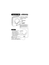
NOTE: Settings can be checked
using the TEST/SETTINGS Button.
SETTING THE HIGH LIMIT
The high limit is factory set at
190°F. To adjust, turn the HI
TEMP Dial A until the desired
setting is displayed. (Setting
range: 100°-220°F)
SETTING THE LOW LIMIT
The low limit is designed to main-
tain temperature in boilers
equipped with tankless coils used
for domestic hot water. The low
limit is factory set to OFF. Prior to
adjusting, remove the jumper (not
equipped on all units) B . Then
turn the LO TEMP Dial C clockwise until the desired
temperature is displayed. For proper operation, the
low temperature limit setting should be at least 10°
below the high limit setting. NOTE: For cold start oper-
ation, the low limit must be turned OFF. IMPORTANT:
If low limit temperature cannot be set above 140°F,
remove jumper B . (Setting range: OFF or 110°-200°F).
SETTING THE ECONOMY FEATURE
The Economy Feature is factory set for a 1 zone heating system.
To adjust, turn the ECONOMY Dial D until the number dis-
played equals the number of heating zones. Do not include indi-
rect water heaters in the number of heating zones. The Economy
Feature conserves fuel by reducing boiler temperature (see “How
Thermal Targeting Works” on page 23). If the heating system is
unable to supply needed heat to the house, the ECONOMY Dial
should be turned to a lower setting (example: In a three zone
house, turn the dial to 2 or 1). Conversely, if the boiler provides
adequate heat, added fuel savings can be achieved by selecting
a higher setting (example: 4 or 5). If the heating and indirect water
heater signals were not separated when wiring the control, the
Economy Feature should be turned OFF to insure the boiler sup-
plies adequate temperature to heat the indirect tank.
SETTING THE CONTROL
BOILERS EQUIPPED WITH HYDROSTAT CONTROL
SETTING
OFF Disables economy function. Will allow boiler to fire until hi
limit temp is reached and re-fire with a 10° subtractive
differential.
LO Provides lowest level of fuel savings. Use this setting only
if the house does not stay warm at higher settings.
1 Recommended setting for single zone systems
2 Recommended setting for Two zone systems
3 Recommended setting for Three zone systems
4 Recommended setting for Four zone systems
5 Recommended setting for Five zone systems
HI Provides highest level of fuel savings
IMPORTANT NOTICE
This boiler is equipped with a feature that saves energy by reducing the boiler water
temperature as the heating load decreases. This feature is equipped with an over-
ride which is provided primarily to permit the use of an external energy manage-
ment system that serves the same function. THIS OVERRIDE MUST NOT BE
USED UNLESS AT LEAST ONE OF THE FOLLOWING CONDITIONS IS TRUE:
• An external energy management system is installed that reduces the boiler water
temperature as the heating load decreases.
•This boiler is not used for any space heating.
•This boiler has an input of 300,000 BTU/hr or greater
• This boiler is part of a modular or multiple boiler system having a total input of
300,000 BTU/hr or greater.
• This boiler is equipped with a tankless coil.

VICTORY II VHS Models
20
NOTE: The Program Mode – Pro – is accessed by turning the
LO TEMP dial to a position just above OFF.
THERMAL PRE-PURGE
Thermal Pre-Purge is designed to maximize boiler efficiency. When activated, the control will supply latent heat that may remain
in the boiler from a previous run cycle to the next heating zone that calls. The control monitors how quickly the boiler tempera-
ture is declining and activates the burner only when it determines that the latent heat is insufficient to satisfy the call.
During the purge cycle, the display will indicate Pur. This feature works with single-zone and multi-zone heating systems utiliz-
ing circulators or zone valves. No change in wiring is needed.
To activate Thermal Pre-Purge
1. Turn the LO TEMP dial to access the Program Mode – indicated in the display as Pro
2. Turn the HI TEMP dial to select feature 1
3. Push the Test/Settings Button to turn Thermal Pre-Purge or OFF
4. Reset LO TEMP and HI TEMP settings to desired temperatures (see page 19
Note: Activation of this feature is not recommended for boilers with tankless coils.
DEGREES FAHRENHEIT OR CELSIUS
The control has the ability to operate in degrees Fahrenheit or Celsius. When operating in Celsius, a will appear in the display
next to the temperature whenever the temperature is below 100 degrees.
To change between degrees Fahrenheit and degrees Celsius
1. Turn the LO TEMP dial to access the Program Mode – indicated in the display as Pro
2. Turn the HI TEMP dial to select feature 2
3. Push the Test/Settings Button to c for Celsius or F for Fahrenheit
4. Reset LO TEMP and HI TEMP settings to desired temperatures (see page 19)
MANUAL RESET LOW WATER CUT-OFF
The low water cut-off operation on the HydroStat can be set to operate in automatic (default) or manual reset mode. When in
manual reset mode, the control will shut-down the burner immediately when a low water condition is detected. If the low water
condition is sustained for 30 seconds, the low water light will blink, indicating that the control has locked out the burner. The
control can only be reset by pushing the Test Settings button on the top of the control. The manual reset feature meets CSD-1
code requirements.
IMPORTANT: The system must be checked by a qualified heating professional prior to resuming operation.
WARNING: DO NOT ADD WATER UNTIL THE BOILER HAS FULLY COOLED.
To activate Manual Reset LWCO mode
1. Turn the LO TEMP dial to access the Program Mode – indicated in the display as Pro
2. Turn the HI TEMP dial to select feature 3
3. Push the Test/Settings Button to A for Automatic Reset Mode or b for Manual Reset Mode
4. Reset LO TEMP and HI TEMP settings to desired temperatures (see page 19
To Test the Manual Reset Feature: Press and hold the Test/Settings button located on the top of the control for 30 seconds to
simulate a low water condition. After 30 seconds, the Low Water light will blink indicating that the control is locked out. To reset
the lock-out condition, press the Test/Settings button momentarily.
MORE OPTIONAL FEATURES ON NEXT PAGE
OPTIONAL FEATURES
/