Page is loading ...

1
WARNING: To ensure that drive is not unexpectedly started,
turn off and lock out or tag power source before proceeding.
Failure to observe these precautions could result in bodily
injury.
DESCRIPTION:
Flexidyne dry uid couplings and drives are unique concepts
to provide soft start and momentary overload protection for all
types of driven equipment. Standard NEMA B motors with RPM
base speeds of 1750, 1160 or 860 are commonly used with a
Flexidyne mechanism, yet other available power sources may be
used with the Flexidyne mechanism.
The dry “Fluid” in the Flexidyne housing is heat treated steel
shot. A measured amount, referred to as ow charge, is added
into a housing which has been keyed to the motor shaft. When
the motor is started, centrifugal force throws the ow charge to
the perimeter of the housing, packs it between the housing and
the rotor which in turn transmits power to the load.
After the starting period of slippage between housing and rotor
the two become locked together and achieve full load speed,
operating without slip.
Consequently, the motor accelerates instantly to base speed,
while the load starts gradually and smoothly.
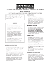
Couplings Drives
Rotor
Output
Sheave
Motor
Shaft
Housing
Flow Charge
Output Shaft
Flow
Charge
Housing
Rotor
Flexible Coupling
Motor Shaft
Figure 1 - Housing cross section
WARNING: Because of the possible danger to persons(s) or
property from accidents which may result from the improper
use of products, it is important that correct procedures be
followed. Products must be used in accordance with the
engineering information specified in the catalog. Proper
installation, maintenance and operation procedures must
be observed. The instructions in the instruction manuals
must be followed. Inspections should be made as necessary
to assure safe operation under prevailing conditions. Proper
guards and other suitable safety devices or procedures as
may be desirable or as may be specified in safety codes
should be provided, and are neither provided by Baldor
Electric Company nor are the responsibility of Baldor
Electric Company. This unit and its associated equipment
must be installed, adjusted and maintained by qualified
personnel who are familiar with the construction and
operation of all equipment in the system and the potential
hazards involved. When risk to persons or property may be
involved, a holding device must be an integral part of the
driven equipment beyond the speed reducer output shaft.
Instruction Manual for No. 55C & 55D
FLEXIDYNE
®
Couplings and Drive
These instructions must be read thoroughly before installing or operating this product.
INSTALLATION:
55C Coupling: Install coupling ange on drive shaft and drive
housing mechanisms on motor shaft in accordance with the
instruction manual for the Taper-Lock® bushings found at
www.baldor.com. Note: The coupling ange must be mounted
on driven shaft (not motor shaft) to allow proper operation of
the Flexidyne coupling. Shaft ends must not protrude beyond
bushing ends. Install coupling disc over pins on drive housing
mechanism. Position the motor and the driven unit so that the
spacer buttons on the coupling disc slightly contact the coupling
ange.
Parallel misalignment should not exceed 1/64” maximum. (See
Fig. 2) For longest Flexidyne coupling life, it is always desirable
to align coupling as accurately as possible at initial installation.
Driven
Motor (Driven)
Figure 2 - Parallel Misalignment
55D Drive: Install sheave on driven hub. When using a Taper-
Lock sheave with #1610 bushing, do not exceed 175 inch-pounds
of wrench torque. When using a QD sheave with SH bushing,
do not exceed 108 inch-pounds of wrench torque. Excessive
tightening may distort the sleeve of the driven hub due to the
wedging action of the bushing.
Note: Special “overbore” keyless bushings are used. Due
to the cushioning effect of the Flexidyne drive, a key is not
required on the sheave.
Do not use sheaves with set screws. These will exert pressure on
the sleeve of the driven hub. Also, they tend to distort the driven
hub and may cause damage to the bronze bushing.
NOTE: Do not remove mounting collar.
Stake motor shaft key in place and slide Flexidyne drive onto
the motor shaft with the collar as close to the motor as possible.
Tighten key set screw securely against motor shaft key, then,
tighten shaft set screw securely against motor shaft.
Do not input power to the Flexidyne drive thru the sheave. The
sheave is the output of the Flexidyne drive.

2
START-UP
1. Remove the ller plug and install the proper amount of
ow charge specied in Table 1. Replace and tighten ller
plug, making sure that no ow charge is trapped in threads.
Torque ller plug to 35 inch-pounds.
2. Attach AC ammeter (conventional clamp-on or equivalent) to
one line of the AC motor. Set range to cover 200% of motor
nameplate current.
3. Note maximum allowable acceleration time for Flexidyne
couplings and drives as stated in Table 1. Note: Table 2 lists
starting time capacity for various starting cycles.
4. Push start button. Observe motor current during load
acceleration and number of seconds required to reach full
speed (Fig. 3).
Increase amount of ow charge if:
A. Acceleration time reaches maximum allowable before
load is up to speed. Turn off power immediately if this
time is reached.
B. Acceleration amperage is below motor nameplate.
Decrease amount of ow charge if:
A. Acceleration time is less than 1 1/2 seconds.
B. Acceleration amperage is above 200% of motor
nameplate.
5. Once satisfactory operation has been obtained record the
following for future reference:
A. The amount of ow charge.
B. Starting current.
C. Acceleration time
CAUTION: The Flexidyne rotor must slip during acceleration
to allow flow charge to become evenly distributed in the
Flexidyne housing. Therefore, DO NOT ALLOW FLEXIDYNE
MECHANISM TO RUN “FREE” (that is, without a load on
the driven end), otherwise an out-of-balance condition may
result, damaging mechanism and attached equipment.
Seconds from Start
Acceleration Amps
Lock-In
400
300
200
100
10
8
6
4
2
In-rush Amps
Running
Amps
%
Figure 3 - Flow Charge Ratio
The amount of ow charge in the Flexidyne housing determines
the acceleration time for a given load. Slower acceleration times
will occur when less ow charge is used and faster acceleration,
from stop to full speed, will be observed with greater amounts of
ow charge. It is recommended to keep the acceleration time as
fast as the system will permit.
OPERATION
The Flexidyne mechanism should start the load smoothly and
without delay provided the proper amount of ow charge has
been used. Should the acceleration time exceed the maximum
allowable in Table 1 on page 3, shut off power to the Flexidyne
mechanism immediately. Allow the Flexidyne mechanism to cool,
then add small amounts of ow charge until proper acceleration
is observed.
Vibration — Vibration is an indication of accelerating too rapidly
and not allowing ow charge to become evenly distributed in
the Flexidyne housing. This can be corrected by removing small
amounts of ow charge until vibration subsides. Other causes of
vibration are, undersize shafting, unit not installed far enough on
shaft or worn bore in the unit.
Slippage — The Flexidyne mechanism can, without slipping,
transmit overloads 30% above pre-set starting torque. Should
this breakaway torque be exceeded the Flexidyne mechanism
will slip and generate heat (see Overload Protection). Although
slippage usually indicates increased loads, it can also be caused
by worn ow charge or a worn rotor especially if the Flexidyne
mechanism has been in operation for some time. The necessity
to replace either a rotor or ow charge will be made evident by a
loss in power transmitting capacity of the Flexidyne mechanism.
MAINTENANCE
For average industrial applications involving 3 or 4 starts a day
and of not more than 6 seconds acceleration time each, the Flow
charge should be changed every 10,000 hours of operation. For
more severe conditions, visually inspect ow charge at more
frequent intervals; it should be changed when it has deteriorated
to a half powder, half granular condition. See page 4 for ow
charge analysis. Visual inspections should continue until enough
ow charge changes have been made to adequately establish a
schedule for renewing Flexidyne ow charge.
The Flexidyne mechanism has been lubricated at the factory and
no further lubrication is required. Never apply grease, oil or any
other foreign material to the flow charge.
THERMAL CAPACITY
Since there is slippage within the ow charge during acceleration,
heat is generated from friction. The thermal capacity of
the Flexidyne mechanism is based on balancing this heat
generated during acceleration against the cooling time between
accelerations. The amount of heat generated is determined
by the amount of horsepower dissipated by slipping and the
duration of each acceleration. If the ow charge weight is light,
the heat generated will not be as great as that which would
be generated with a heavier ow charge, when compared at
the same acceleration time. A longer time between starts will
dissipate more heat; therefore, higher starting horsepowers may
be transmitted, or longer acceleration times may be allowable.
(See Starting Cycle in Table 2)
Acceleration times shown in Table 1 are for starting frequencies
of one start per hour or less. If starting frequency is more than
once per hour, use acceleration time for actual starting cycle
shown in Table 2.
Acceleration times listed in Tables 1 and 2 are the MAXIMUM
permissible for the various starting frequencies listed. The
MINIMUM acceleration time required for proper Flexidyne
mechanism operation is 1 to 1½ seconds. This is the time required
for the ow charge to be uniformly distributed around the housing
cavity before the unit “locks in”. Any acceleration time between
the minimum and maximum listed is acceptable, although a
shorter acceleration time will generally provide longer wear life.
For applications requiring a specic acceleration time (within
these limits) ow charge may be added or removed to produce
the required results.

3
Stalled — if a jam-up stalls the drive, the motor continues to
run and the Flexidyne mechanism slips. This causes heat to be
generated at twice the rate of normal acceleration. Therefore,
the allowable slipping time, when stalled, is half the allowable
acceleration time given in Table 1.
Starting Cycle is the time from the beginning of one acceleration
to the beginning of the next. Allowable acceleration times in Table
2 are based on the assumption that the Flexidyne mechanism
will be running continuously except for a momentary stop before
the next start. If the stop is more than momentary, decrease the
actual starting cycle by one-half the stopped time before using
Table 2; for example, with a 50 minute actual starting cycle of
which 20 minutes is stopped time, decrease 50 by half of 20 to
give 40 minutes as the starting cycle time to use for Table 2.
Grouped Starts — For several starts grouped together followed
by uninterrupted running, add the acceleration times of all starts
and consider it as the time for one start. The starting cycle would
be the time from the beginning of one group of starts to the
beginning of the next group.
OVERLOAD PROTECTION
WARNING: The user is responsible for conforming with the
National Electrical Code and all other applicable codes.
Wiring Practices, grounding , disconnects and overcurrent
protection are of particular importance. Failure to observe
these precautions could result in severe bodily injury or loss
of life.
Table 1 - Flow Charge Recommendations
Based on % Starting Torque for 1760 RPM NEMA Design B Motors
Rated
Motor
HP
Flexidyne
Mechanism
Size
100% @ 1760 RPM 125% @ 1750 RPM 150% @ 1740 RPM 175% @ 1700 RPM 200% @ 1650 RPM
Starting
HP
Flow
Charge
Max
Time in
Sec. ①
Starting
HP
Flow
Charge
Max
Time in
Sec. ①
Starting
HP
Flow
Charge
Max
Time in
Sec. ①
Starting
HP
Flow
Charge
Max
Time in
Sec. ①
Starting
HP
Flow
Charge
Max
Time in
Sec. ①
Lbs. Oz. Lbs. Oz. Lbs. Oz. Lbs. Oz. Lbs. Oz.
1 55 1.0 0 9 125 1.2 0 10 110 1.5 0 11 92 1.7 0 12 84 1.9 0 13 78
1-1/2 55 1.5 0 10 92 1.9 0 12 78 2.2 0 13.5 72 2.5 0 14 67 2.8 0 16 63
2 55 2.0 0 12 76 2.5 0 13.5 67 3.0 0 15 60 3.4 1 1 56 3.8 1 2 53
Based on % Starting Torque for 1175 RPM NEMA Design B Motors
Rated
Motor
HP
Flexidyne
Mechanism
Size
100% @ 1175 RPM 125% @ 1160 RPM 150% @ 1150 RPM 175% @ 1130 RPM 200% @ 1100 RPM
Starting
HP
Flow
Charge
Max
Time in
Sec. ①
Starting
HP
Flow
Charge
Max
Time in
Sec. ①
Starting
HP
Flow
Charge
Max
Time in
Sec. ①
Starting
HP
Flow
Charge
Max
Time in
Sec. ①
Starting
HP
Flow
Charge
Max
Time in
Sec. ①
Lbs. Oz. Lbs. Oz. Lbs. Oz. Lbs. Oz. Lbs. Oz.
1/2 55 .50 0 11 250 .60 0 12 200 .75 0 13 175 .80 0 15 160 .90 1 0 148
3/4 55 .75 0 12 175 .90 0 15 148 1.1 1 0 130 1.3 1 1 115 1.4 1 2 110
① Maximum Allowable Acceleration Time for one start per hour, or less. Proper application of the Flexidyne mechanism requires that the load be connected. Without connected load
acceleration time may be too fast to allow change to be distributed for proper balance.
Table 2 - Thermal Capacity for No. 55C & 55D Flexidyne Mechanisms
Starting
HP ①
Maximum Allowable Acceleration Time in Seconds for Standard Motor Speeds at Various Starting Cycles
2 Hours 1 Hour 30 Minutes 15 Minutes 10 Minutes 5 Minutes 2 Minutes 1 Minute
1160 1750 1160 1750 1160 1750 1160 1750 1160 1750 1160 1750 1160 1750 1160 1750
.50 250 ... 250 ... 250 ... 250 ... 190 ... 110 ... 60 ... 33 ...
.75
175 ... 175 ... 175 ... 175 ... 130 ... 80 ... 40 ... 26 ...
1.0 148 125 148 125 148 125 148 125 110 96 68 58 35 30 22 19
1.5 110 92 110 92 110 92 110 92 82 67 50 41 28 23 18 15
2.0 ... 76 ... 76 ... 76 ... 76 ... 60 ... 37 ... 20 ... 13
2.5 ... 67 ... 67 ... 67 ... 67 ... 52 ... 32 ... 17 ... 11
3.0 ... 60 ... 60 ... 60 ... 60 ... 47 ... 29 ... 15 ... 9
3.5 ... 55 ... 55 ... 55 ... 55 ... 43 ... 25 ... 13 ... 8
4.0 ... 50 ... 50 ... 50 ... 50 ... 40 ... 20 ... 10 ... 6
① Starting HP is determined by amount of flow charge installed, see Table 1.

World Headquarters
P.O. Box 2400, Fort Smith, AR 72902-2400 U.S.A., Ph: (1) 479.646.4711, Fax (1) 479.648.5792, International Fax (1) 479.648.5895
Dodge Product Support
6040 Ponders Court, Greenville, SC 29615-4617 U.S.A., Ph: (1) 864.297.4800, Fax: (1) 864.281.2433
www.baldor.com
© Baldor Electric Company
MN4033 (Replaces 499867)
All Rights Reserved. Printed in USA.
9/10 PRINTSHOP 200
*4033-0910*
Flexidyne Mechanism Trouble Analysis
Symptom Cause Cure
Vibration 1. Misalignment
2. Bent shaft
3. Excess ow charge
4. Fused ow charge
5. Improper installation – Output shaft
jammed against housing
1. Realign drive or coupling.
2. Replace or straighten.
3. Remove small amount of ow charge.
4. Correct the overload.
5. Readjust spacing between shafts and
Flexidyne housing.
Erratic Acceleration 1. Breakdown of ow charge
2. Caked ow charge
3. Below minimum amount of ow
charge
1. Replace ow charge.
2. Moist environment – use stainless
ow charge.
3. Add ow charge.
Flexidyne Mechanism Doesn’t Slip 1. Improper installation – Output shaft
jammed against housing
2. Flow charge in bearings – causing
bearing seizure
1. Readjust spacing between shafts and
Flexidyne housing.
2. Replace seals, bearings and
ow charge or replace Flexidyne
mechanism.
Excessive Slippage 1. Not enough ow charge
2. Overload
3. Worn ow charge
4. Worn rotor
1. Add ow charge.
2. Relieve overload
3. Replace ow charge.
4. Replace rotor.
Poor or short ow charge life 1. Excessive slip at start up
2. Excessive inching or jogging of
machine
1. Add ow charge to reduce starting
time.
2. Install time delay in motor control
circuit.
Flexidyne Mechanism Flow Charge Analysis
Condition Cause
1. Red oxide color, granular consistency
2. Red oxide color, powdery consistency, possibly with
powdery akes
3. Black, powdery
4. Red oxide, powdery and chunky
5. Clumping of ow charge
1. Normal after some usage.
2. Worn-out, can cause Flexidyne mechanism damage.
3. Rotor worn, excessive slip and heat.
4. Worn-out and moisture present.
5. Moisture present, use stainless ow charge.
PARTS REPLACEMENT
The 55C and 55D FLEXIDYNE mechanisms were not designed to
be repaired. Normal care in installation and operation will yield
long, dependable life of the unit.
Miscellaneous accessory parts are available and should be
ordered with complete description of part and 6 digit part
number.
Table 3 - Parts Replacement
Name of Part
No. Required Part Numbers
Per Unit 55C 55D
Flexidyne Coupling
Mechanism (complete)
Flexidyne Drive Mechanism
(5/8” Bore) (complete)
Flexidyne Drive Mechanism
(7/8” Bore) (complete)
-
-
-
305019
............
............
............
305015
305016
Filler Plug
Filler Plug Lockwasher
1
1
305018
419190
305018
419190
Coupling Element
Coupling Flange
{
Type ‘H
Type ‘F’
1
1
008030
008057
008058
............
............
............
Collar
Collar Set screw
Collar Set Screw
1
1
1
............
............
............
305134
400022
400030
/