Shelter Logic CPH202007 Owner's manual

Type
Owner's manual
www.arrowsheds.com
Customer Service:
1-800-851-1085 or
BUILDING DIMENSIONS
20’ x 20’
Nominal Size
Gloves must be worn
at all times to reduce
risk of injury!
Size rounded off to the nearest foot
* See Inside for Detailed Safety Information.
Owner’s Manual
& Assembly Guide
01DD
724910118
Base
Size
247” x 221”
627 cm x 561 cm
Exterior Dimensions
(Roof Edge to Roof Edge)
Width Depth Height
Interior Dimensions
Width Depth Height
Entrance
Height
Width (max)
Height
(min)
Approx.
Size
Storage
Area
20’ x 20’ 390 Sq. Ft. 3250 Cu. Ft. 243” 237” 118” 237” 237” 116” 237” 84.4” 82”
6,1 m x 6,1 m 36,2 m
2
92 m
3
617 cm 602 cm 300 cm 602 cm 602 cm 295 cm 602 cm 214 cm 208 cm
Model No. CPH202007
3
SAFETY & MAINTENANCE
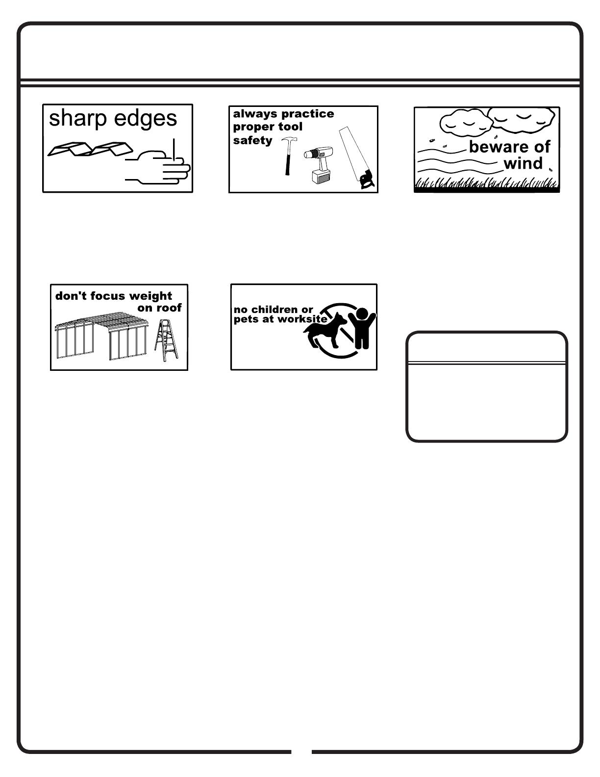
Safety precautions MUST be followed at all times throughout the construction of your building!
Care must be taken when handling
various pieces of your building since
many contain sharp edges. Please
wear work gloves, eye protection and
long sleeves when assembling or
performing any maintenance on your
building.
Practice caution with the tools being
used in the assembly of this building.
Be especially familiar with the
operation of all power tools.
Keep children and pets away from the
worksite during construction and until
the building is completely assembled.
This will help avoid distractions and
any accidents which may occur.
NEVER concentrate your weight on
the roof of the building. When using
a step ladder make sure that it is
fully open and on even ground before
climbing on it.
Do NOT attempt to assemble your
building on a windy day. The large
panels can catch the wind like a “sail”,
causing them to be whipped around
making construction diffi cult and
unsafe.
Do NOT attempt to assemble your
building before double checking that
you have all the parts indicated on the
parts list as well as all hardware. Any
building left partially assembled may be
seriously damaged by even light winds.
IMPORTANT NOTE ON
ANCHORING
• Your building MUST be anchored to
prevent wind damage. See anchoring
page for more info.
• You must also have a temporary
anchoring system in place in case you
need to take a break from assembly.
03BQ
Exterior Care:
For a long lasting fi nish, clean and wax the exterior surface. We recommend washing with a mild soap solution. DO NOT use power washing
to clean your shed. Using a spray automotive type wax periodically on the exterior is highly recommended if you are in a high humidity or
coastal climate region.
Combustibles and corrosives must be stored in air tight containers designed for chemical and/or combustible storage. Corrosive chemicals
such as fertilizers, pesticides and herbicides should be cleaned off the interior and exterior surfaces immediately. Rust caused by chemical
damage is not covered by the warranty.
Rust protection precautions may help to stop rust from developing, or stop it quickly as soon as it appears.
Avoid nicking or scraping the coating surface, inside and out.
• Keep roof and base perimeter free of debris and leaves which may accumulate and retain moisture. These can do double damage since
they give off acid as they decay.
• Touch up scrapes or nicks and any area of visible rust as soon as possible. Make sure the surface is free of moisture, oils, dirt or grime and
then apply an even fi lm of high quality touch-up paint.
• Various paint manufacturers provide products for rust treatment and coverage. If surface rust does appear on your shed we recommend
treating those areas as soon as possible, following the paint supplier of your choice instructions.
Our customer service department can provide the paint tinting formula for matching the color of your shed. We also have touch-up paint
available for repairing small nicks and scratches.
Roof: Keep the roof clear of leaves and snow. Heavy amounts of snow on the roof can damage the building making it unsafe to enter.
Fasteners: Regularly check fasteners and retighten as necessary.
General: Wash off inked part numbers on coated panels with soap and water.
Please note, Manufacturer cannot be held responsible for any consequences due to buildings that are not installed per these instructions, or
for damage due to weather conditions or acts of God.
Keep these assembly instructions and owners manual for future reference.
7
ASSEMBLY TIPS & TOOLS
How to Select and Prepare Your Building Site: Before you start to assemble your
building, you will want to decide on a good location. The best location is a level area with good drainage.
Allow enough working space so it is not diffi cult to move parts into position for assembly. Also, there needs to be enough
space outside the building to be able to fasten the panel screws from the outside.
• Before assembling any parts, your base should be constructed and an anchoring system should be ready to use.
Watch the Weather Closely: Be sure the day you choose to install your building is dry and calm.
Do NOT attempt to assemble your building on a windy day. Be careful on wet or muddy ground.
Use Teamwork: Two or more people are required to assemble your building. One person can hold
the parts or panels in place while the other person fastens them together and handles the tools. This
makes the process of assembling your building faster and safer.
Tools and Materials: Here is a list of some basic tools and materials you will need to assemble
your building. Decide which method of anchoring and the type of base you will use to make a complete
list of the materials you will need.
Work Gloves
Safety Glasses
Nut Driver or Wrench
Step Ladder 8’
Power Drill (Cordless, Variable Speed)
Pliers
Utility Knife or Scissors
Carpenter’s Level
Tape Measure
Clamp
Square
String (for squaring the frame)
Awl (to align holes)
PVC Pipe
Ratchet Straps
Lumber and/or Concrete
Hammer and Nails
Spade or Shovel
Hand Saw or Power Saw
RECOMMENDED TIME SAVERS
BASE PREPARATION TOOLS
07EZ
WHAT YOU NEED
11
08BM
Confi rm that all hardware and parts are present before attempting to assemble
your Storage Unit.
Customer Service:
1-800-851-1085 or [email protected]
For missing or damaged parts contact Customer Service. Do not return to store.
Vérifi er la présence de toutes les pièces et la visserie avant de commencer à
assembler le coffre de rangement.
Si des pièces manquent ou sont endommagées, s’adresser au Service après-vente. Ne
rien renvoyer au magasin.
Service après-vente :
1-800-851-1085 ou [email protected]
Confi rme que todos los artículos de ferretería estén presentes antes de empezar
a ensamblar su unidad de almacenamiento.
Si hay piezas faltantes o dañadas, comuníquese con el Servicio de Atención al Cliente.
No devuelva el producto a la tienda.
Servicio de Atención al Cliente:
1-800-851-1085 o [email protected]
Vergewissern Sie sich, dass alle Teile da sind, bevor Sie versuchen, Ihre Gartenbox
aufzustellen.
Wenden Sie sich bei fehlenden oder beschädigten Teilen an den Kundendienst. Wenden
Sie sich nicht an den Händler.
Kundendienst:
1-800-851-1085 oder [email protected]
8
NOTE: 20’ x 20’ x 7’ is the BASE frame dimension. Your model may have more middle ribs than shown in the illustrations. You will
receive one additional middle rib and seven middle roof panels for every additional 4.5 ft. of building length that you purchase.
The basic frame assembly remains the same.
REMARQUE: L’armature de base mesure 6,1 x 6,1 x 2,1 m. Votre abri peut comporter davantage de nervures centrales que
l’illustrations. Vous recevez une nervure additionnelle pour chaque section supplémentaire de 1,35 m. L’assemblage de l’armature
de base reste le même.
NOTA: 20’ x 20’ x 7’ es la dimensión bancada. Su modelo podrá contar con más costillas medias que se muestran en las ilustra-
ciones. Usted recibirá una costilla adicional por cada adicional de 4.5 pies de longitud edifi cio que usted compra. El conjunto de
bastidor básico sigue siendo el mismo.
HINWEIS: Die Abmessungen des BASIS-Rahmens sind 20 Fuß x 20 Fuß x 7 Fuß. Ihr Modell kann mehr mittlere Versteifungen als
in den Abbildungen gezeigt haben. Pro 4,5 Fuß Gebäudelänge, die Sie kaufen, erhalten Sie eine zusätzliche mittlere Versteifung
und sieben mittlere Dachbleche. Der Basisrahmen bleibt gleich.
FRAME OVERVIEW • VUE D'ENSEMBLE DU CADRE
DESCRIPCIÓN GENERAL DEL MARCO • RAHMEN ÜBERSICHT
14
Extension Modules • Modules d’extension
Módulos de extensión • Erweiterungsmodule
14DD
8
15DD
NOTE: The 20’W x 20’L x7’H is a base building. Buildings longer than 20’ will receive 2 additional boxes for each 4.5’, one frame
box with 1 middle rib and one panel box with 11 middle panels. These frames and panels are inserted in the middle section of
the base building.
REMARQUE: La construction de 6,1 m (20 pi) L x 6,1 m (20 pi) l x 2,13 m (7 pi) H constitue l’édifi ce de base. Les constructions de
plus de 6,1 m (20 pi) comprennent 2 boîtes supplémentaires pour chaque 1,37 m (4,5 pi) : une boîte de cadre avec une nervure
centrale et une boîte de panneaux avec 11 panneaux centraux. Ces cadres et panneaux sont insérés dans la section centrale
de l’édifi ce de base.
NOTA: La construcción de 20’ de ancho x 20’ de largo x 7’ de altura constituye el edifi cio de base. Para los edifi cios con una
longitud mayor que 20’, recibirá 2 cajas adicionales por cada 4,5’: una caja de armazón con un nervio central y una caja de panel
con 11 paneles centrales. Estos armazones y paneles se insertan en la sección central del edifi cio de base.
HINWEIS: Die 20 Fuß Breite x 20 Fuß Länge x 7 Fuß Höhe sind ein Basis-Gebäude. Gebäude, die länger als 20 Fuß sind, er-
halten pro 4,5 Fuß 2 zusätzliche Kisten, eine Rahmenkiste mit einer mittleren Versteifung und eine Bleche-Kiste mit 11 mittleren
Blechen. Diese Rahmen und Bleche werden im mittleren Abschnitt des Basis-Gebäudes eingesetzt.
Extension Module Parts
G 805693
H 805698
I 805792
K 805673
L 805699
M 11061
Q 805726
R 805724
P 805728
Part Name
* Teilbezeichung
* Nombre de la pieza
* Désignation de la pièce
Qty
* Menge
* Cantidad
* Quantité
1
4
2
2
2
11
1
1
2
Pièces de module d’extension
Piezas del módulo de expansión
Erweiterungsmodulteile
15
15
Step 4A / Étape 4A / Paso 4A / Schritt 4A
14EZ
19
X
Y
X=Y
(x2)
STEP 1 / ÉTAPE 1 /
PASO 1 / SCHRITT 1
15
Step 5A / Étape 5A / Paso 5A / Schritt 5A
20EZa
21
804860
A
(x16)
(x2)
STEP 2 / ÉTAPE 2 /
PASO 2 / SCHRITT 2
A
x4
6
Step 6 / Étape 6 / Paso 6 / Schritt 6
23
21DD
(x10) (x1) (x10)
D D
C
C
E
C
00828
D
E
00825 10016
X
Y
X=Y
E
20
Step 7A / Étape 7A / Paso 7A / Schritt 7A
22EZ
24
53-3/4”
(136.525 cm)
x4
x4
Cut PVC pipes or similar spacers to length (shown
below). 1” (2,54 cm) diameter minimum. Used to keep
frame space equal.
Couper les tuyaux en PVC ou les entretoises similaires à
la longueur souhaitée (voir ci-dessous). Diamètre mini-
mum de 1 ”(2,54 cm). Utilisé pour garder le même espace
d’image.
Corte los tubos de PVC o espaciadores similares a la
longitud (como se muestra a continuación). 1 ”(2,54
cm) de diámetro mínimo. Se utiliza para mantener el
espacio del marco igual.
Schneiden Sie PVC-Rohre oder ähnliche Ab-
standhalter auf Länge ab (siehe unten). Mindest-
durchmesser 1 ”(2,54 cm). Wird verwendet, um den
Bildraum gleich zu halten.
20
Step 7B / Étape 7B / Paso 7B / Schritt 7B
22EZa
25
Fasten ribs with ratchet straps to tighten the frame for
roof panel assembly.
Fixez les nervures avec des sangles à cliquet pour
serrer le cadre lors de l’assemblage du panneau de
toit.
Fije las costillas con las correas de trinquete para
apretar el marco para el ensamblaje del panel del
techo.
Befestigen Sie die Rippen mit Ratschenbändern, um
den Rahmen für die Dachverkleidung festzuziehen.
x3
Ne pas enlever les tuyaux ou
les sangles avant d’avoir reçu
l’instruction
Do not remove pipes or
straps until instructed
No retire tuberías ni correas
hasta que se le indique.
Entfernen Sie keine Rohre oder
Gurte, bis Sie dazu aufgefordert
werden
NOTE
REMARQUE NOTA HINWEIS
25
Step 12 / Étape 12 / Paso 12 / Schritt 12
26EZ
30
804860
A
(x104)
66856
M
11061
(x8)
N
11060
(x8)
O
N
1
16
N
N
N
N
N
N
N
M
M
M
M
M
M
M
M
2
3
4
5
6
7
8
9
10
11
12
13
14
15
REAR
Dos
Posterior
Hinten
FRONT
Avant
Frente
Vorne
Enlevez les sangles à cliquet et les entretoises
avant de monter la dernière rangée de panneaux
Remove ratchet straps and spacers
before assembling last row of panels
Retire las correas de trinquete y los espaciadores
antes de ensamblar la última fi la de paneles
Entfernen Sie vor dem Zusammenbau der letzten
Paneelreihe Ratschenbänder und Abstandhalter
NOTE
REMARQUE NOTA HINWEIS
26
Step 13 / Étape 13 / Paso 13 / Schritt 13
29EZ
31
Apply straps and spacers to other side of the frame
Appliquez des sangles et des entretoises de l’autre
côté du cadre
Aplique correas y espaciadores al otro lado del
marco.
Befestigen Sie Riemen und Abstandshalter auf der
anderen Seite des Rahmens
FRONT
Avant
Frente
Vorne
REAR
Dos
Posterior
Hinten
  • Page 1 1
  • Page 2 2
  • Page 3 3
  • Page 4 4
  • Page 5 5
  • Page 6 6
  • Page 7 7
  • Page 8 8
  • Page 9 9
  • Page 10 10
  • Page 11 11
  • Page 12 12
  • Page 13 13
  • Page 14 14
  • Page 15 15
  • Page 16 16
  • Page 17 17
  • Page 18 18
  • Page 19 19
  • Page 20 20
  • Page 21 21
  • Page 22 22
  • Page 23 23
  • Page 24 24
  • Page 25 25
  • Page 26 26
  • Page 27 27
  • Page 28 28
  • Page 29 29
  • Page 30 30
  • Page 31 31
  • Page 32 32
  • Page 33 33
  • Page 34 34

Shelter Logic CPH202007 Owner's manual

Type
Owner's manual

Ask a question and I''ll find the answer in the document

Finding information in a document is now easier with AI