Page is loading ...

Note: To order replacement parts specify the model and serial number of your machine.
Shaded parts represent 57841 Assembly.
Always operate, inspect and maintain this tool in accordance with the Safety Code for portable air tools
(ANSI B186.1) and any other applicable safety codes and regulations. Please refer to Dynabrade’s
Warning/Safety Operating Instructions for more complete safety information.
WARNING
!
Air-Powered “Jitterbug -Type” Sander
Small Grip, 10,000 RPM, 3/32" Dia. Orbit
Models:
57860 – Non-Vacuum
57861 – Vac-Ready
57862 – Basic Vacuum
57863 – Deluxe Vacuum
57864 – Central Vac-Ready
Dynabug Orbital Sander
57850 Non-Vac, Vinyl Face
57851 Non-Vac, “Hook” Face
57852 Non-Vac, Long “Nap Hook” Face
57855 Vac, Vinyl Face
57856 Vac, “Hook” Face
Pad Bases
Parts Page Reorder No. PD01•33
Effective March, 2001
57877 — Non-Vacuum
57878 — Self Generated Vac
57879 — Central-Vac
Housing
A
T
O
O
1
A
2
A
6
A
8
O
1
Adhesive: A
2
= Loctite #271
A
6
= Loctite #380
A
8
= Loctite #567
Torque: N•m x 8.85 = In. - lbs.
Oil: O
1
= Air Lube
1.6 N•m
T
2.0 N•m
T
11.3 N•m
T
0.7 N•m
T
28 N•m
T
23 N•m
T
1 96258 Screw (4)
2 96168 Screw
3 57834 Rubber Grip (2)
4 95183 Washer
5 57838 Washer
6 96114 Screw (6)
7 96115 Clip Post (2)
8 57826 Clip Top (2)
9 57840 Clip Spring (2)
10 57825 Pad Top
11 57837 Washer
12 57842 Vacuum Tube
13 57822 Boot
14 57823 Pad Mount
15 96116 Clamp
16 95630 Snap Ring
17 57069 Balancer Shaft
18 95628 Bearing Shield
19 56053 Bearing Seal
20 56052 Balancer Bearing
21 57839 Motor Balancer Shaft
22 56047 Rotor Key
23 57059 Lock Ring Seal
24 95973 Washer
25 57055 Front Ring
26 57088 Bearing
27 57057 Front Bearing Plate
28 57113 Blade (5/pkg), Rotor Set
29 57058 Cylinder Assembly
(Includes 95971 Pin)
30 95971 Line-Up Pin
31 57056 Rear Bearing Plate
32 01206 Bearing
33 57054 Rear Ring
34 95626 Snap Ring
35 95979 Pin
36 57820 Lever
37 01464 Seal
38 01472 Tip Valve
39 01468 Conical Spring
40 01494 Inlet Bushing
41 95697 Snap Ring
42 01025 O-Ring (2)
43 01477 Valve Stem
44 57064 Speed Regulator
Index Key
No. Part # Description
34
35
36
37 38
39
40
33
32
31
29
28
27
26
25
24
12
15
41
42
43
44
14
13
11
9
8
7
3
6
10
5
4
2
1
23
21
20
19
18
17
16
22
30
KEY
See page 2 for Machine Exhaust Assemblies.
A
2

57083 Vacuum Adapter
57065 Cone Muffler 57066 Muffler Body
95526 O-Ring
96197 Dowel Pin
57068 Vac Nozzle
57067 Vac Tube
Machine Exhaust Assemblies
Self Generated Vacuum (Vac-Ready) / Machine Exhaust
For Models: 57861, 57862, 57863
(PD01•33)
2
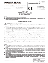
Important Operating, Maintenance and Safety Instructions
Carefully read all instructions before operating or servicing any Dynabrade
®
Abrasive Power Tool.
Warning: Hand, wrist and arm injury may result from repetitive work motion and overexposure to vibration.
Important: All Dynabrade rotary vane air tools must be used with a Filter-Regulator-Lubricator to maintain all warranties.
Operating Instructions:
Warning: Eye, face, respiratory, sound and body protection must be worn while operating power tools. Failure to do so may result in serious injury or death.
Follow safety procedures posted in workplace.
1. With power source disconnected from tool, securely fasten abrasive/accessory on tool.
2. Install air fitting into inlet bushing of tool. Important: Secure inlet bushing of tool with a wrench before attempting to install the air fitting to avoid
damaging valve body housing.
3. Connect power source to tool. Be careful not to depress throttle lever in the process.
4. Check tool speed with tachometer. If tool is operating at a higher speed than the RPM marked on the tool or operating improperly, the tool should be
serviced to correct the cause before use.
Maintenance Instructions:
1. Check tool speed regularly with a tachometer. If tool is operating at a higher speed than the RPM marked on the tool, the tool should be serviced to
correct the cause before use.
2. Some silencers on air tools may clog with use. Clean and replace as required.
3. All Dynabrade Rotary Vane air motors should be lubricated. Dynabrade recommends one drop of air lube per minute for each 10 SCFM (example: if the
tool specifications state 40 SCFM, set the drip rate of your filter-lubricator at 4 drops per minute). Dynabrade Air Lube (P/N 95842: 1pt. 473ml.)
is recommended.
4. An Air Line Filter-Regulator-Lubricator must be used with this air tool to maintain all warranties. Dynabrade recommends the following: 11405 Air Line
Filter-Regulator-Lubricator — Provides accurate air pressure regulation, two-stage filtration of water contaminants and micro-mist lubrication of pneumatic
components. Operates 40 SCFM @ 100 PSIG with 3/8" NPT female ports.
5. Use only genuine Dynabrade replacement parts. To reorder replacement parts, specify the Model #, Serial #, and RPM of your machine.
6. A Motor Tine-Up Kit (P/N 96024) is available which includes assorted parts to help maintain motor in peek operating condition.
7. Mineral spirits are recommended when cleaning the tool and parts. Do not clean tool or parts with any solvents or oils containing acids, esters, keytones,
chlorinated hydrocarbons or nitro carbons.
57093 Vacuum Adapter
57065 Cone Muffler
57066 Muffler Body
56027 Muffler Insert (2)**
56028 Muffler Cap
57065 Cone Muffler
57066 Muffler Body
56027 Muffler Insert (2)**
56028 Muffler Cap
Central Vacuum / Machine Exhaust
For Model: 57864
Non-Vacuum / Machine Exhaust
For Model: 57860
** Muffler inserts available in Package of 30 - P/N 56054.
• Important: User of tool is responsible for following accepted safety codes such as those published by the American National Standards Institute (ANSI).
• Operate machine for one minute before application to workpiece to determine if machine is working properly and safely before work begins.
• Always disconnect power supply before changing abrasive/accessory or making machine adjustments.
• Inspect abrasives/accessories for damage or defects prior to installation on tools.
• Please refer to Dynabrade’s Warning/Safety Operating Instructions Tag (Reorder No. 95903) for more complete safety information.
Safety Instructions:
Products offered by Dynabrade should not be converted or otherwise altered
from original design without expressed written consent from Dynabrade, Inc.
Model Motor Motor Air Inlet Sound Air Flow Rate Air Pressure Hose I.D. Weight Length Height
Number HP (W) RPM Thread Level CFM/SCFM (LPM) PSIG (Bars) Inch (mm) Pound (kg) Inch (mm) Inch (mm)
All Models .18 (134) 10,000 1/4" NPT 83 dB(A) 3/18 (510) 90 (6.2) 1/4" (8 mm) 2.75 (1.2) 7-1/4 (184) 4-1/4 (108)

Motor Assembly/Disassembly Instructions – Dynabug Orbital Sander
Important: Manufacturer’s warranty is void if tool is disassembled before warranty expires.
A Motor Repair Kit (57098) is available which contains special tools for disassembly/assembly. Please refer to parts breakdown for part identification.
To Disassemble:
1. Disconnect tool from power source. Invert machine and secure in vice, using 57092 Collar (supplied in 57098 Repair Kit) or padded jaws.
2. Disconnect sanding pad by removing 96258 Screws (4) with a 3 mm wrench.
3. With a Phillips head screw driver remove 96114 Screws (6). Remove 96168 Screw with 3/16" hex wrench, and remove pad top from boot.
4. Disengage 96116 Clamp by using a screwdriver to unscrew clamp. Remove clamp, 57822 Boot and 57823 Pad Mount from housing.
5. Insert 56058 Lock Ring Tool (supplied in 57098 Repair Kit) into corresponding tabs of lock ring and unscrew. Motor may now be lifted out for service.
6. Remove rear ring from motor. Upper motor may now be disassembled. Remove 95626 Snap Ring.
7 Remove the rear plate and the cylinder assembly by securing the cylinder in a bearing separator gripped on the cylinder exhaust and extra pocket area.
Push the motor shaft balancer through the bearing.
8. Remove the rotor, vanes and rotor key from the motor shaft balancer. Remove the front plate using a (#2) arbor press. Support the edges of the
front plate while pressing on the small end of the motor shaft balancer.
9. a.) If, during step 9, the front plate and bearing remain together, press bearing out of the front plate using 57091 Press Tool (supplied in 57098 Repair Kit).
b.) If, during step 9, the front plate and 57088 Bearing remains on the motor shaft balancer, it can be removed with a bearing separator.
11. Remove 01206 Bearing from the rear plate by using a bearing press tool. Remove lock ring, washer and front ring.
12. Disassemble the balancer assembly as follows:
a.) Place motor shaft assembly into a soft jaw vise. Using a thin screwdriver, pick out the end of 95630 Snap Ring and peel out.
b.) Screw the threaded portion of the 56056 Bearing Puller (supplied in 57098 Repair Kit) into the 57069 Balancer Shaft and heat the outside of the
motor shaft balancer to approximately 200° F (approximately 10 seconds with a propane torch). Now, using the slider weight, pull the assembly out.
c.) Press off 56052 Bearing with a bearing separator and remove bearing seal and bearing shield.
13. If during step 12, the 56052 Bearing remains in the motor shaft balancer, it can be removed by heating the shaft balancer again and using either an
inside bearing puller or a blind hole bearing puller.
Tool disassembly complete.
To Assemble
Important: Be certain parts are clean and in good repair before assembling.
1. Assemble the balancer assembly as follows:
a.) Install 95630 Snap Ring onto 57069 Balancer Shaft. Install 95628 Shield with convex face toward hex of balancer shaft. Install 56053 Seal.
Note: Be certain seal is pressed completely over shaft step.
b.) Apply 1 drop of #271 Loctite
®
(or equivalent) and spread over several places around the inside diameter of the 56052 Bearing and the outside
diameter of the 57069 Balancer Shaft.
c.) Press fit 56052 Bearing with seal side toward hex of balancer shaft up to shaft step. This must be a firm press fit for proper retention of bearing.
2. Place the motor shaft balancer in a soft jaw vise with large end-up.
3. Apply 1 drop of #271 Loctite
®
(or equivalent) and spread over several places around the outside diameter of the 56052 Bearing and slide balancer
assembly into the motor shaft balancer until 56052 Bearing is firmly seated at bottom. Squeeze 95630 Snap Ring into groove in motor shaft balancer to
complete the assembly. Remove from vise.
4. Press 57088 Bearing onto the motor shaft balancer down to the shoulder. Place lock ring, washer and front ring on motor shaft balancer.
5. Press 57057 Front Bearing Plate onto 57088 Bearing and check for smooth rotation.
6. Place the 57090 Rotor and 56047 Rotor Key on the motor shaft balancer. Place the 56073 Vanes into the rotor slots.
Note: Vanes should be lightly lubricated with Dynabrade Air Lube P/N 95842 (or equivalent) before installation into the rotor slots.
7. Place 57058 Cylinder Assembly over rotor. The “short” line-up pin goes toward the front plate.
8. Place 57056 Rear Bearing Plate (with rear bearing pressed into place) over shaft and “long” end of line-up pin and press fit in place. Insert
95626 Snap Ring.
9. Place 57054 Rear Ring over the rear plate and line-up pin. Make sure that the “legs and fingers” on the front and rear rings line-up.
10. Secure motor housing in vise, using 57092 Collar or padded jaws. Spread 2-3 drops of pneumatic tool oil around the housing bore and slide motor
assembly in housing. Note: Be certain line-up pin enters the pocket in bottom of the housing and the “legs” of the rings stay in line.
11. Tighten lock ring with 56058 Lock Ring Tool torque to 28 N•m/250 in. - lbs.
12. Insert 57823 Pad Mount into boot. Attach boot to housing with exhaust hole facing back and slide clamp over boot.
13. Place 57837 Washer into hex pocket with shoulder down. Line-up holes in pad top with holes in boot and secure with 96114 Screws (6).
14. Secure pad top and boot to motor assembly by installing 57838 Washer, 95183 Washer and 96168 Screw through pad top and into balancer shaft.
15. Position pad top to desired angle and tighten clamp to 0.7 N•m/6 in. - lbs. so that the top of the clamp is even with the top of the boot.
16. Attach sanding pad by installing 96258 Screws (4).
Valve and Speed Regulator Assemblies:
1. Secure housing in vice using 57092 Collar or padded jaws. Remove inlet bushing, 01468 Spring, 01472 Tip Valve and 01464 Seal from housing.
2. Remove 95697 Snap Ring. Press the speed regulator and valve stem out of the housing. Remove the 01025 O-Rings (2).
3. Place new 01025 O-Rings (2) on the speed regulator and place in housing with valve stem. Install new 95967 Snap Ring.
4. Place seal in housing. Using tweezers or needle nose pliers, place the tip valve in the housing so that its pin goes into the valve stem hole. Place
01468Spring into the housing so the small end is toward the tip valve.
5. Spread one drop of #567 Loctite
®
(or equivalent) around the first threads of the first inlet bushing and tighten into housing torque to 23 N•m/200 in. - lbs.
Tool assembly is complete. Please allow 30 minutes for adhesives to cure before operating tool.
Loctite
®
is a registered trademark of the Loctite Corp.
3

57098 Motor Repair Kit:
Includes special tools for proper
disassembly/assembly of the machine.
96024 Motor Tune-Up Kit:
Includes assorted parts to help
maintain and repair motor.
Accessories
Vacuum Conversion Instructions
To Disassemble:
1. Disconnect tool from power source. Invert machine and secure in vise, using 57092 Collar (supplied in 57098 Repair Kit) or padded jaws.
2. Remove 56028 Muffler Cap and 56027 Muffler Insert (3) from 57066 Muffler Body. Using a 12 mm hex wrench (supplied in 57098 Repair Kit), remove
muffler body and 57065 Cone Muffler from housing (not applicable for self-generated vac to central vac).
Non-Vac to Self-Generated Vac for Hook-Up to Self-Contained Dust Collection System
1. Attach 57083 Vacuum Adapter to 57842 Vacuum Tube using 4 drops of #380 Loctite
®
. Then attach to the housing making sure the tube is secured in
the hole in the pad top.
2. Place 95526 O-Ring on the muffler body between the shoulder and the four (4) protrusions. Using a 12 mm hex wrench, attach the muffler body, cone
muffler and o-ring to the housing through the vacuum adapter.
3. Place vacuum nozzle into the vacuum adapter with the slots facing outward making sure that the knob on the nozzle is aligned with the slot in the adapter.
4. Place 57067 Vacuum Tube into the vacuum adapter with the grooves facing inward until the adapter “snaps” onto the tube and the tube cannot be pulled
out. If the tube can be pulled out, rotate it 1/4 turn and place it back into the adapter until it “snaps”.
5. Rotate tube until holes line up. Insert 96197 Dowel Pin in holes until it is centered.
6. Attach machine to portable dust collection system.
Non-Vac to Central Vac
1. Attach 57093 Vacuum Adapter to 57842 Vacuum Tube using 4 drops of #380 Loctite
®
. Then attach to the housing making sure the tube is secured in
the hole in the pad top.
2. Using a 12 mm hex wrench, attach the muffler body and cone muffler to the housing through the central vacuum adapter.
3. Place muffler cap with inserts on muffler body making sure that the protrusions on the body fit in the pockets on the cap.
4. Attach machine to central vacuum system.
Self-Generated Vac to Central Vac
1. Remove 96197 Dowel Pin with an 1/8" drive pin.
2. Remove 57067 Vacuum Tube from the 57083 Vacuum Adapter by turning it clockwise while pulling backward.
3. Using a small flat screwdriver, pry the vacuum nozzle until it is loose and then remove it by using two fingers to push and pull it until it hits the “legs” on the
vacuum adapter. Place the vacuum tube back into the vacuum adapter far enough to push the “legs” back then push the vacuum nozzle and the vacuum
tube out the rest of the way.
4. Using a 12 mm hex wrench (supplied in 57098 Repair Kit), remove the 57066 Muffler Body, 57065 Cone Muffler and 95526 O-Ring from the housing
through the adapter. Remove the o-ring from the muffler body.
5. Remove 57083 Vacuum Adapter and attach 57093 Vacuum Adapter to 57842 Vacuum Tube using 4 drops of #380 Loctite
®
.
6. Using a 12 mm hex wrench, attach the muffler body, cone muffler and o-ring to the housing through the central vacuum adapter.
7. Place muffler cap with inserts on muffler body making sure that the protrusions on the body fit in the pockets on the cap.
8. Attach machine to central vacuum system.
Central Vac to Self Generated Vac
1. Remove 57093 Central Vacuum Adapter and put the 57083 Vacuum Adapter to 57842 Vacuum Tube using 4 drops of #380 Loctite
®
.
2. Place 95526 O-Ring on the muffler body between the shoulder and the four (4) protrusions. Using a 12 mm hex wrench (supplied in 57098 Repair Kit),
attach the muffler body, cone muffler and o-ring to the housing through the vacuum adapter.
3. Place vacuum nozzle into the vacuum adapter with the slots facing outward making sure that the knob on the nozzle is aligned with the slot in the adapter.
4. Place 57067 Vacuum Tube into the vacuum adapter with the grooves facing inward until the adapter “snaps” onto the tube and the tube cannot be pulled
out. If the tube can be pulled out, rotate it 1/4 turn and place it back into the adapter until it “snaps”.
5. Rotate tube until holes line up. Insert 96197 Dowel Pin in holes until it is centered.
6. Attach machine to portable dust collection system.
DYNABRADE
®
DYNABRADE, INC., 8989 Sheridan Drive • Clarence, NY 14031-1490 • Phone: (716) 631-0100 • Fax: 716-631-2073 • International Fax: 716-631-2524
DYNABRADE EUROPE S.àr.l., Zone Artisanale • L-5485 Wormeldange—Haut, Luxembourg • Telephone: 352 76 84 94 1 • Fax: 352 76 84 95 1
© DYNABRADE, INC., 2001 PRINTED IN USA
Visit our Web Site: www.dynabrade.com Email: Customer.Service@Dynabrade
/