
MODEL NO. PO17542STC
17.5 HP 42 Inch
Lawn Tractor
191798 03.01.04 TR
PRINTED IN U.S.A.
For Parts and Service, contact our authorized distributor: call 1-800-849-1297
For Technical Assistance: call 1-800-829-5886

2
• Avoid starting or stopping on a slope. If tires lose trac-
tion, disengage the blades and proceed slowly
straight
down the slope.
DO NOT:
•
Do not
turn on slopes unless necessary, and then,
turn slowly and gradually downhill, if possible.
•
Do not
mow near drop-offs, ditches, or embankments.
The mower could suddenly turn over if a wheel is over
the edge of a cliff or ditch, or if an edge caves in.
•
Do not
mow on wet grass. Reduced traction could
cause sliding.
•
Do not
try to stabilize the machine by putting your foot
on the ground.
•
Do not
use grass catcher on steep slopes.
III. CHILDREN
Tragic accidents can occur if the operator is not alert to the pres-
ence of children. Children are often attracted to the ma chine
and the mowing activity.
Never
assume that children will remain
where you last saw them.
• Keep children out of the mowing area and under the
watchful care of another responsible adult.
• Be alert and turn machine off if children enter the
area.
• Before and when backing, look behind and
down
for
small children.
• Never carry children. They may fall off and be seriously
injured or interfere with safe machine operation.
• Never allow children to operate the machine.
• Use extra care when approaching blind corners, shrubs,
trees, or other objects that may obscure vision.
IV. SERVICE
• Use extra care in handling gasoline and other fuels.
They are fl ammable and vapors are explosive.
- Use only an approved container.
- Never remove gas cap or add fuel with the engine
running. Allow engine to cool before refueling. Do
not smoke.
- Never refuel the machine indoors.
- Never store the machine or fuel container inside where
there is an open fl ame, such as a water heater.
• Never run a machine inside a closed area.
• Keep nuts and bolts, especially blade attachment bolts,
tight and keep equipment in good condition.
• Never tamper with safety devices. Check their proper
op er a tion regularly.
• Keep machine free of grass, leaves, or other debris
build-up. Clean oil or fuel spillage. Allow machine to
cool before storing.
• Stop and inspect the equipment if you strike an object.
Repair, if necessary, before restarting.
• Never make adjustments or repairs with the engine
run ning.
• Grass catcher components are subject to wear, dam-
age, and deterioration, which could expose moving
parts or allow objects to be thrown. Frequently check
com po nents and replace with manufacturer's rec om -
mend ed parts, when nec es sary.
• Mower blades are sharp and can cut. Wrap the blade(s)
or wear gloves, and use extra caution when servicing
them.
• Check brake operation frequently. Adjust and service
as required.
I. GENERAL OPERATION
• Read, understand, and follow all instructions in the
manual and on the machine before starting.
• Only allow responsible adults, who are familiar with the
in struc tions, to operate the machine.
• Clear the area of objects such as rocks, toys, wire, etc.,
which could be picked up and thrown by the blade.
• Be sure the area is clear of other people before mow-
ing. Stop machine if anyone enters the area.
• Never carry passengers.
• Do not mow in reverse unless absolutely necessary.
Always look down and behind before and while back-
ing.
• Be aware of the mower discharge direction and do not
point it at anyone. Do not operate the mower without
either the entire grass catcher or the guard in place.
• Slow down before turning.
• Never leave a running machine unattended. Always
turn off blades, set parking brake, stop engine, and
remove keys before dismounting.
• Turn off blades when not mowing.
• Stop engine before removing grass catcher or un-
clog ging chute.
• Mow only in daylight or good artifi cial light.
• Do not operate the machine while under the infl uence
of alcohol or drugs.
• Watch for traffi c when operating near or crossing road-
ways.
• Use extra care when loading or unloading the machine
into a trailer or truck.
• Data indicates that operators, age 60 years and above,
are involved in a large percentage of riding mower-re-
lated injuries. These operators should evaluate their
ability to operate the riding mower safely enough to
protect them selves and others from serious injury.
• Keep machine free of grass , leaves or other debris
build-up which can touch hot exhaust / engine parts
and burn. Do not allow the mower deck to plow leaves
or other debris which can cause build-up to occur.
Clean any oil or fuel spillage before operating or
storing the machine. Allow machine to cool before
storage.
II. SLOPE OPERATION
Slopes are a major factor related to loss-of-control and tipover
accidents, which can result in severe injury or death. All slopes
require extra caution. If you cannot back up the slope or if you
feel uneasy on it, do not mow it.
DO:
• Mow up and down slopes, not across.
• Remove obstacles such as rocks, tree limbs, etc.
• Watch for holes, ruts, or bumps. Uneven terrain could
overturn the machine.
Tall grass can hide obstacles.
• Use slow speed. Choose a low gear so that you will
not have to stop or shift while on the slope.
• Follow the manufacturer’s recommendations for wheel
weights or counterweights to improve stability.
• Use extra care with grass catchers or other at tach ments.
These can change the stability of the machine.
• Keep all movement on the slopes
slow
and
gradual
.
Do not make sudden changes in speed or direction.
SAFETY RULES
SAFE OPERATION PRACTICES FOR RIDE-ON MOWERS
IMPORTANT: THIS CUTTING MACHINE IS CAPABLE OF AMPUTATING HANDS AND FEET AND THROW ING OBJECTS. FAILURE
TO OBSERVE THE FOLLOWING SAFETY INSTRUCTIONS COULD RESULT IN SERIOUS INJURY OR DEATH.

3
WARNING: In order to prevent ac-
ci den tal starting when setting up,
trans port ing, ad just ing or making re-
pairs, al ways dis con nect spark plug
wire and place wire where it can not
contact spark plug.
WARNING: Do not coast down a hill
in neutral, you may lose control of the
tractor.
WARNING: Tow only the attachments
that are rec om mend ed by and com-
ply with spec i fi ca tions of the man u -
fac tur er of your tractor. Use common
sense when towing. Operate only at
the low est possible speed when on a
slope. Too heavy of a load, while on
a slope, is dan ger ous. Tires can lose
trac tion with the ground and cause you
to lose control of your tractor.
• Be sure the area is clear of other people before mowing. Stop
machine if anyone enters the area.
• Never carry passengers or children even with the blades
off.
• Do not mow in reverse unless absolutely necessary. Al ways
look down and behind before and while backing.
• Never carry children. They may fall off and be seriously injured
or interfere with safe machine operation.
• Keep children out of the mowing area and under the watchful
care of another responsible adult.
• Be alert and turn machine off if children enter the area.
• Before and when backing, look behind and down for small
children.
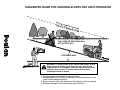
• Mow up and down slopes (15° Max), not across.
• Remove obstacles such as rocks, tree limbs, etc.
• Watch for holes, ruts, or bumps. Uneven terrain could overturn
the machine. Tall grass can hide obstacles.
• Use slow speed. Choose a low gear so that you will not have
to stop or shift while on the slope.
• Avoid starting or stopping on a slope. If tires lose traction,
disengage the blades and proceed slowly straight down the
slope.
• If machine stops while going uphill, disengage blades, shift
into reverse and back down slowly.
• Do not turn on slopes unless necessary, and then, turn slowly
and gradually downhill, if possible.
WARNING
Engine exhaust, some of its con stit u ents, and cer-
tain vehicle com po nents contain or emit chem i cals
known to the State of Cal i for nia to cause can cer and
birth de fects or oth er re pro duc tive harm.
WARNING
Battery posts, terminals and related ac ces so ries
contain lead and lead compounds, chem i cals known
to the State of Cal i for nia to cause can cer and birth
defects or oth er re pro duc tive harm. Wash hands
after handling.
SAFETY RULES
SAFE OPERATION PRACTICES FOR RIDE-ON MOWERS

4
TABLE OF CONTENTS
SAFETY RULES ......................................................... 2-3
PRODUCT SPECIFICATIONS ....................................... 4
CUSTOMER RESPONSIBILITIES................................. 4
ASSEMBLY ................................................................. 6-8
OPERATION ............................................................. 9-13
MAINTENANCE SCHEDULE ...................................... 14
MAINTENANCE ..................................................... 14-17
SERVICE AND AD JUST MENTS ............................ 18-23
STORAGE .................................................................... 24
TROU BLE SHOOT ING ............................................ 25-26
REPAIR PARTS ......................................................28-41
WARRANTY................................................................. 43
CONGRATULATIONS on your purchase of a new tractor.
It has been designed, engineered and manu fac tured to give
you the best possible dependability and performance.
Should you experience any problem you cannot easily rem-
edy, please contact your nearest authorized service center/
department. We have com pe tent, well-trained tech ni cians
and the proper tools to ser vice or repair this tractor.
Please read and retain this manual. The instructions will
enable you to assemble and maintain your tractor prop erly.
Always observe the “SAFETY RULES”.
CUSTOMER RESPONSIBILITIES
• Read and observe the safety rules.
• Follow a regular schedule in maintaining, caring for
and using your tractor.
• Follow the instructions under “Maintenance” and “Stor-
age” sec tions of this own er’s manual.
WARNING: This tractor is equipped with an internal com-
bus tion engine and should not be used on or near any
un im proved forest-covered, brush-covered or grass-cov ered
land unless the engine’s exhaust system is equipped with
a spark arrester meeting applicable local or state laws (if
any). If a spark arrester is used, it should be maintained
in effective working order by the operator.
A spark arrester for the muffl er is available through your
nearest authorized service center/department (See RE PA I R
PARTS section of this manual).
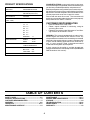
GASOLINE CAPACITY 1.25 GALLONS
AND TYPE: UNLEADED REGULAR
OIL TYPE (API-SF-SJ): SAE 30 (above 32°F)
SAE 5W-30 (below 32°F)
OIL CAPACITY: 3.0 PINTS
SPARK PLUG: CHAMPION RC12YC
(GAP: .030")
GROUND SPEED (MPH): FORWARD:
1st 1.1
2nd 1.4
3rd 2.2
4th 3.4
5th 4.3
6th 5.5
REVERSE: 1.7
TIRE PRESSURE: FRONT: 14 PSI
REAR: 12 PSI
CHARGING SYSTEM: 3 AMPS BATTERY
5 AMPS HEADLIGHTS
BATTERY: AMP/HR: 28
MIN. CCA: 230
CASE SIZE: U1R
BLADE BOLT TORQUE: 27-35 FT. LBS.
PRODUCT SPECIFICATIONS

5
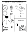
CONTENTS OF HARDWARE PACK
Steering Wheel
Seat
Keys
Slope Sheet
(1) Oil Drain Tube
(1) Bolt
(1) Washer
17/32 x 1-3/16 x 12 Gauge
(1) Lock
Washer 1/2
(1) Large Flat Washer
(1) Hex Bolt 1/4-28 x 1-1/4
(1) Locknut 1/4-28
(1) Locknut 1/2-20
(2) Keys
Steering Wheel
Adapter
Steering
Wheel
Insert
Steering
Boot
Steering
Extension
Shaft

6
ASSEMBLY
TOOLS REQUIRED FOR ASSEMBLY
A socket wrench set will make assembly easier. Stan dard
wrench sizes are listed.
(2) 7/16" wrenches Utility knife
(2) 3/4" wrench Tire pres sure gauge
Pliers
When right or left hand is mentioned in this man ual, it means
when you are in the operating po si tion (seated be hind the
steer ing wheel).
TO REMOVE TRACTOR FROM
CAR TON
UNPACK CARTON
• Remove all accessible loose parts and parts cartons
from carton.
• Cut along dotted lines on all four panels of carton.
Remove end panels and lay side panels fl at.
• Check for any additional loose parts or cartons and
remove.
Your new tractor has been assembled at the factory with exception of those parts left unassembled for shipping purposes.
To ensure safe and proper operation of your tractor all parts and hardware you assemble must be tightened securely. Use
the correct tools as necessary to insure proper tightness.
FIG. 1
02
599
1/4 LOCKNUT
LOWER
STEERING
SHAFT
STEERING
BOOT
EXTENSION SHAFT
1/4 HEX BOLT
STEERING
WHEEL
INSERT
ADAPTER
1/2 HEX NUT
LARGE FLAT
WASHER
TABS
TAB
SLOTS
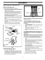
BEFORE REMOVING TRACTOR FROM
SKID
ATTACH STEERING WHEEL (See Fig. 1)
ASSEMBLE EXTENSION SHAFT AND BOOT
• Slide extension shaft onto lower steering shaft. Align
mount ing holes in extension and lower shafts and install
1/4 hex bolt and lock nut. Tighten securely.
IMPORTANT: TIGHTEN BOLT AND NUT SECURELY TO
10-12 FT. LBS TORQUE.
• Place tabs of steering boot over tab slots in dash and
push down to secure.
INSTALL STEERING WHEEL
• Position front wheels of the tractor so they are pointing
straight forward.
• Remove steering wheel adapter from steering wheel
and slide adapter onto steer ing shaft ex ten sion.
• Position steering wheel so cross bars are hor i zon tal
(left to right) and slide inside boot and onto adapt er.
• Assemble large fl at washer, 1/2 hex nut and tighten
se cure ly.
• Snap steering wheel insert into center of steer ing
wheel.
• Remove protective materials from tractor hood and
grill.
IMPORTANT: CHECK FOR AND RE MOVE ANY STA PLES
IN SKID THAT MAY PUNC TURE TIRES WHERE TRACTOR
IS TO ROLL OFF SKID.

7
ASSEMBLY
FIG. 2
TO ROLL TRACTOR OFF SKID (See Op-
er a tion section for location and func tion of
con trols)
• Press lift lever plunger and raise attachment lift lever
to its highest po si tion.
• Release parking brake by depressing clutch/brake
ped al.
• Place gearshift lever in neutral (N) po si tion.
• Roll tractor forward off skid.
• Remove banding holding defl ector shield up against
tractor.
TO DRIVE TRACTOR OFF SKID (See Op-
er a tion sec tion for lo ca tion and func tion of
con trols)
WARNING: Before starting, read, un der stand and follow
all in struc tions in the Operation section of this manual. Be
sure tractor is in a well-ventilated area. Be sure the area in
front of tractor is clear of other people and objects.
• Be sure all the above assembly steps have been com-
pleted.
• Check engine oil level and fi ll fuel tank with gasoline.
• Sit on seat in operating position, depress clutch/brake
pedal and set the parking brake.
• Place gear shift lever in neutral (N) position.
• Press lift lever plunger and raise attachment lift lever
to its highest position.
• Start the engine. After engine has started, move throttle
control to idle position.
• Depress clutch/brake pedal into full “BRAKE” position
and hold. Move gearshift lever to 1st gear.
• Slowly release clutch/brake pedal and slowly drive
tractor off skid.
• Apply brake to stop tractor, set parking brake and place
gearshift lever in neutral position.
• Turn ignition key to “OFF” position.
Continue with the instructions that follow.
FIG. 3
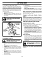
CHECK BATTERY (See Fig. 3)
• Lift seat pan to raised position.
• If this battery is put into service after month and year
indicated on label (label located between terminals)
charge battery for minimum of one hour at 6-10 amps.
(See "BATTERY" in MAINTENANCE section of this
manual for charging instructions).
02602
SEAT PAN
LABEL
TERMINAL
TERMINAL
ADJUSTMENT
BOLT
LOCK WASHER
HOW TO SET UP YOUR TRACTOR
INSTALL SEAT (See Fig. 2)
Adjust seat before tightening adjustment bolt.
• Remove adjustment bolt, lock washer and fl at washer
se cur ing seat to cardboard packing and set aside for
as sem bly of seat to tractor.
• Pivot seat upward and remove from the cardboard pack-
ing. Remove the cardboard packing and discard.
• Place seat on seat pan so head of shoulder bolt is
positioned over large slotted hole in pan.
• Push down on seat to engage shoulder bolt in slot and
pull seat towards rear of tractor.
• Pivot seat and pan forward and assemble adjust-
ment bolt, lockwasher and fl at washer loosely. Do not
tighten
• Lower seat into operating position and sit on seat.
• Slide seat until a comfortable position is reached
which allows you to press clutch/brake pedal all the
way down.
• Get off seat without moving its adjusted position.
• Raise seat and tighten adjustment bolt securely.
2466
02465
SEAT PAN
SHOULDER
BOLT
FLAT WASHER
SEAT
NOTE: You may now roll or drive your tractor off the skid.
Follow the appropriate instruction below to remove the
tractor from the skid.

8
ASSEMBLY
✓
CHECKLIST
BEFORE YOU OPERATE AND ENJOY YOUR NEW TRAC-
TOR, WE WISH TO ASSURE THAT YOU RECEIVE THE
BEST PER FOR MANCE AND SATISFACTION FROM THIS
QUALITY PROD UCT.
PLEASE REVIEW THE FOLLOWING CHECKLIST:
✓ All assembly instructions have been completed.
✓ No remaining loose parts in carton.
✓ Battery is properly prepared and charged. (Minimum
1 hour at 6 amps).
✓ Seat is adjusted comfortably and tightened securely.
✓ All tires are properly infl ated. (For shipping purposes,
the tires were overinfl ated at the factory).
✓ Be sure mower deck is properly leveled side-to-side/
front-to-rear for best cutting results. (Tires must be
properly infl ated for leveling).
✓ Check mower and drive belts. Be sure they are routed
properly around pulleys and inside all belt keepers.
✓ Check wiring. See that all connections are still secure
and wires are properly clamped.
WHILE LEARNING HOW TO USE YOUR TRACTOR, PAY
EX TRA ATTENTION TO THE FOLLOWING IMPORTANT
ITEMS:
✓ Engine oil is at proper level.
✓ Fuel tank is fi lled with fresh, clean, regular unleaded
gas o line.
✓ Become familiar with all controls - their location and
function. Operate them before you start the engine.
✓ Be sure brake system is in safe operating condition.
CHECK TIRE PRESSURE
The tires on your tractor were overinfl ated at the factory
for shipping purposes. Correct tire pressure is important
for best cutting performance.
• Reduce tire pressure to PSI shown in “PRODUCT
SPEC I FI CA TIONS” section of this manual.
CHECK DECK LEVELNESS
For best cutting results, mower housing should be properly
leveled. See “TO LEVEL MOWER HOUSING” in the Service
and Adjustments section of this manual.
CHECK FOR PROPER POSITION OF ALL
BELTS
See the fi gures that are shown for replacing motion and
mower blade drive belts in the Service and Adjustments
sec tion of this manual. Verify that the belts are routed
correctly.
CHECK BRAKE SYSTEM
After you learn how to operate your tractor, check to see that
the brake is properly adjusted. See “TO ADJUST BRAKE”
in the Service and Adjustments section of this manual.

9
OPERATION
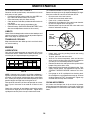
These symbols may appear on your tractor or in literature supplied with the product. Learn and understand their mean-
ing.
DANGER, KEEP HANDS
AND FEET AWAY
FREE WHEEL
(Automatic Models only)
OVER TEMP
LIGHT
KEEP AREA CLEAR
SLOPE HAZARDS
15
15
(SEE SAFETY RULES SECTION)
BATTERY
REVERSE
FORWARD
FAST
SLOW
ENGINE ON
ENGINE OFF
OIL PRESSURE
LIGHTS ON
FUEL
CHOKE
MOWER HEIGHT
PARKING BRAKE
LOCKED
PARKING BRAKE
UNLOCKED
REVERSE
NEUTRAL
HIGH
LOW
ATTACHMENT
CLUTCH ENGAGED
PARKING BRAKE
IGNITION
ATTACHMENT
CLUTCH DISENGAGED
P
ENGINE START
MOWER LIFT
Failure to follow instructions
could result in serious injury or
death. The safety alert symbol
is used to identify safety inform-
ation about hazards which can
result in death, serious injury
and/or property damage.
DANGER indicates a hazard which, if not avoided,
will result in death or serious injury.
WARNING indicates a hazard which, if not avoided,
could result in death or serious injury.
CAUTION indicates a hazard which, if not avoided,
might result in minor or moderate injury.
CAUTION when used without the alert symbol,
indicates a situation that could result in damage
to the tractor and/or engine.
FIRE indicates a hazard which, if not avoided,
could result in death, serious injury and/or
property damage.
HOT SURFACES indicates a hazard which,
if not avoided, could result in death, serious injury
and/or property damage.

10
OPERATION
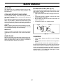
KNOW YOUR TRACTOR
READ THIS OWNER'S MANUAL AND SAFETY RULES BEFORE OPERATING YOUR TRACTOR
Compare the illustrations with your tractor to familiarize yourself with the locations of various controls and ad just ments.
Save this manual for future reference.
ATTACHMENT CLUTCH LEVER - Used to engage the
mower blades, or other attachments mounted to your
tractor.
LIGHT SWITCH POSITION - Turns the headlights on and
off.
THROTTLE/CHOKE CONTROL - Used for starting and
con trol ling engine speed.
CLUTCH/BRAKE PEDAL - Used for declutching and brak-
ing the tractor and starting the engine.
PARKING BRAKE - Locks clutch/brake pedal into the
brake position.
AMMETER - Indicates charging (+) or discharging (-) of
battery.
GEARSHIFT LEVER - Selects the speed and di rec tion
of the tractor.
ATTACHMENT LIFT LEVER - Used to raise, lower, and
adjust the mower deck or other attachments mounted to
your tractor.
LIFT LEVER PLUNGER - Used to release attachment lift
lever when changing its position.
IGNITION SWITCH - Used for starting and stopping the
engine.
Our tractors conform to the safety standards of the American National Standards Institute.
FIG. 4
PARKING
BRAKE
CLUTCH/
BRAKE
PEDAL
THROTTLE/
CHOKE
CONTROL
GEAR SHIFT
LEVER
ATTACHMENT
LIFT LEVER
LIFT LEVER
PLUNGER
IGNITION
SWITCH
ATTACHMENT
CLUTCH LEVER
LIGHT SWITCH
POSITION
HEIGHT
ADJUSTMENT
LEVER
AMMETER

11
01844
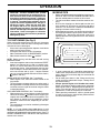
NOTE: Under certain conditions when tractor is standing
idle with the engine running, hot engine exhaust gases may
cause “brown ing” of grass. To eliminate this possibility, al-
ways stop engine when stopping tractor on grass areas.
CAUTION: Always stop tractor com-
plete ly, as described above, before leav-
ing the operator's position; to empty
grass catch er, etc.
OPERATION
The operation of any tractor can result in foreign objects thrown into the eyes, which can result
in severe eye dam age. Always wear safety glass es or eye shields while operating your tractor or
per form ing any adjustments or repairs. We rec om mend a wide vision safety mask over spectacles
or stan dard safety glasses.
00155
HOW TO USE YOUR TRACTOR
TO SET PARKING BRAKE (See Fig. 5)
Your tractor is equipped with an operator presence sens-
ing switch. When engine is running, any attempt by the
op er a tor to leave the seat without fi rst setting the parking
brake will shut off the engine.
• Depress clutch/brake pedal into full “BRAKE” position
and hold.
• Place parking brake lever in “ENGAGED” position and
re lease pressure from clutch/brake pedal. Pedal should
re main in “BRAKE” position. Make sure parking brake
will hold tractor secure.
PARKING BRAKE
"DISENGAGED"
POSITION
FIG. 5
CLUTCH/BRAKE
PEDAL "DRIVE"
POSITION
STOPPING (See Fig. 5)
MOWER BLADES -
• To stop mower blades,move attachment clutch lever
to “DIS EN GAGED” po si tion.
GROUND DRIVE -
• To stop ground drive, depress clutch/brake pedal into
full “BRAKE” po si tion.
• Move gearshift lever to neutral (N) po si tion.
ENGINE -
• Move throttle control to slow po si tion.
NOTE: Failure to move throttle control to slow position and
allowing engine to idle before stopping may cause engine
to “backfi re”.
• Turn ignition key to “OFF” position and remove key.
Always remove key when leaving tractor to prevent
un au tho rized use.
• Never use choke to stop engine.
IMPORTANT: LEAVING THE IGNITION SWITCH IN ANY
POSITION OTHER THAN "OFF" WILL CAUSE THE BATTERY
TO BE DIS CHARGED, (DEAD).
ATTACHMENT CLUTCH
LEVER "ENGAGED"
POSITION
IGNITION KEY
"DIS EN GAGED"
POSITION
PARKING BRAKE
"EN GAGED"
POSITION
GEAR SHIFT
LEVER
THROT TLE/
CHOKE
CONTROL
LEVER
"BRAKE"
POSITION
TO USE THROTTLE CONTROL (See Fig. 5)
Always operate engine at full throttle.
• Operating engine at less than full throttle reduces the
battery charging rate.
• Full throttle of fers the best bagging and mower per for -
mance.
TO MOVE FORWARD AND BACKWARD (See
Fig. 5)
The direction and speed of movement is controlled by the
gearshift lever.
• Start tractor with clutch/brake pedal depressed and
gearshift lever in neutral (N) position.
• Move gearshift lever to desired position.
• Slowly release clutch/brake pedal to start move-
ment.
IMPORTANT: BRING TRACTOR TO A COMPLETE STOP
BEFORE SHIFTING OR CHANGING GEARS. FAILURE
TO DO SO WILL SHORTEN THE USEFUL LIFE OF YOUR
TRANSAXLE.
TO ADJUST MOWER CUTTING HEIGHT (See
Fig. 5)
The position of the attachment lift lever determines the
cutting height.
• Grasp lift lever.
• Press plunger with thumb and move lever to desired
position.
The cutting height range is approximately 1-1/2 to 4".
The heights are measured from the ground to the blade tip
with the engine not running. These heights are approximate
and may vary depending upon soil conditions, height of
grass and types of grass being mowed.
• The average lawn should be cut to approximately 2-1/2
inches during the cool season and to over 3 inches
during hot months. For healthier and better looking
lawns, mow often and after moderate growth.
• For best cutting performance, grass over 6 inches
in height should be mowed twice. Make the fi rst cut
relatively high; the second to desired height.

12
TO OPERATE ON HILLS
WARNING: Do not drive up or down
hills with slopes great er than 15° and
do not drive across any slope.
• Choose the slowest speed before starting up or down
hills.
• Avoid stopping or changing speed on hills.
• If slowing is necessary, move throttle control lever to
slower position.
• If stopping is absolutely necessary, push clutch/brake
pedal quickly to brake position and engage parking
brake.
• Move gearshift lever to 1st gear. Be sure you have
allowed room for tractor to roll slightly as you restart
movement.
• To restart movement, slowly release parking brake and
clutch/brake pedal.
• Make all turns slowly.
OPERATION
01994
AT TACH MENT
CLUTCH LEVER
"DISENGAGED"
PO SI TION
ATTACHMENT
LIFT LEVER
HIGH PO SI TION
"ENGAGED" POSITION
LOW
POSITION
FIG. 6
DEFLECTOR
SHIELD
TO TRANSPORT
• Raise attachment lift to highest position with at tach ment
lift control.
• When pushing or towing your tractor, be sure gearshift
lever is in neutral (N) position.
• Do not push or tow tractor at more than fi ve (5) MPH.
NOTE: To protect hood from damage when transporting
your tractor on a truck or a trailer, be sure hood is closed
and secured to tractor. Use an appropriate means of tying
hood to tractor (rope, cord, etc.).
TOWING CARTS AND OTHER AT TACH -
MENTS
Tow only the attachments that are recommended by and
comply with specifi cations of the manufacturer of your trac-
tor. Use common sense when towing. Too heavy of a load,
while on a slope, is dangerous. Tires can lose traction with
the ground and cause you to lose control of your tractor.
ADD GASOLINE
• Fill fuel tank to bottom of fi ller neck. Do not overfi ll.
Use fresh, clean, regular un lead ed gasoline with a
minimum of 87 octane. (Use of leaded gasoline will
increase carbon and lead oxide deposits and reduce
valve life). Do not mix oil with gasoline. Purchase fuel
in quan ti ties that can be used within 30 days to assure
fuel freshness.
CAUTION: Wipe off any spilled oil or
fuel. Do not store, spill or use gasoline
near an open fl ame.
IMPORTANT: WHEN OPERATING IN TEMPERATURES
BELOW32°F(0°C), USE FRESH, CLEAN WINTER GRADE
GAS O LINE TO HELP INSURE GOOD COLD WEATHER
START ING.
TO OPERATE MOWER (See Fig. 6)
Your tractor is equipped with an operator presence sens-
ing switch. Any attempt by the operator to leave the seat
with the engine running and the attachment clutch engaged
will shut off the engine. You must remain fully and centrally
positioned in the seat to prevent the engine from hesitat-
ing or cutting off when operating your equipment on rough,
rolling terrain or hills.
• Select desired height of cut.
• Start mower blades by engaging attachment clutch
control.
• TO STOP MOWER BLADES - disengage attachment
clutch con trol.
CAUTION: Do not operate the mower
without either the en tire grass catcher,
on mowers so equipped, or the defl ector
shield in place.
BEFORE STARTING THE ENGINE
CHECK ENGINE OIL LEVEL
The engine in your tractor has been shipped, from the
factory, already fi lled with sum mer weight oil.
• Check engine oil with tractor on level ground.
• Remove oil fi ll cap/dipstick and wipe clean, reinsert the
dipstick and screw cap tight, wait for a few seconds,
remove and read oil level. If necessary, add oil until
“FULL” mark on dipstick is reached. Do not overfi ll.
• For cold weather operation you should change oil for
easier starting (See “OIL VISCOSITY CHART” in the
Maintenance sec tion of this manual).
• To change engine oil, see the Maintenance section in
this manual.

13
OPERATION
TO START ENGINE (See Fig. 5)
When starting the engine for the fi rst time or if the engine
has run out of fuel, it will take extra cranking time to move
fuel from the tank to the engine.
• Sit on seat in operating position, depress clutch/brake
pedal and set parking brake.
• Place gear shift lever in neutral (N) position.
• Move attachment clutch to “DISENGAGED” position.
• Move throttle control to choke (
) position.
NOTE: Before starting, read the warm and cold starting
pro ce dures below.
• Insert key into ignition and turn key clockwise to “START”
position and release key as soon as engine starts.
Do not run starter continuously for more than fi fteen
sec onds per minute. If the engine does not start after
several attempts, move throttle control to fast position,
wait a few minutes and try again. If engine still does
not start, move the throttle control back to the choke (
) position and retry.
WARM WEATHER STARTING (50° F and above)
• When engine starts, move the throttle control to the
fast position.
• The attachments and ground drive can now be used. If
the engine does not accept the load, restart the engine
and allow it to warm up for one minute using the choke
as described above.
COLD WEATHER STARTING ( 50° F and below)
• When engine starts, allow engine to run with the throttle
control in the choke (
) position until the engine runs
roughly, then move throttle control to fast position. This
may require an engine warm-up period from several
seconds to several minutes, depending on the tem-
per a ture.
• The attachments can also be used during the engine
warm-up period.
NOTE: If at a high altitude (above 3000 feet) or in cold
tem per a tures (below 32 F) the carburetor fuel mixture may
need to be adjusted for best engine performance. See “TO
ADJUST CAR BU RE TOR” in the Service and Adjustments
section of this manual.
CAUTION: Alcohol blended fuels (called
gas o hol or using ethanol or methanol) can at-
tract moisture which leads to sep a ra tion and
for ma tion of acids during storage. Acidic gas
can damage the fuel system of an engine while
in storage. To avoid engine problems, the fuel
system should be emptied before stor age of
30 days or longer. Drain the gas tank, start
the engine and let it run until the fuel lines
and carburetor are empty. Use fresh fuel next
sea son. See Storage In struc tions for additional
information. Never use engine or carburetor
cleaner products in the fuel tank or permanent
damage may occur.
MOWING TIPS
• Mower should be properly leveled for best mowing per-
for mance. See "TO LEVEL MOWER HOUSING" in the
Service and Adjustments section of this manual.
• The left hand side of mower should be used for trim-
ming.
• Drive so that clippings are discharged onto the area
that has been cut. Have the cut area to the right of the
machine. This will result in a more even distribution of
clippings and more uniform cutting.
• When mowing large areas, start by turning to the right so
that clippings will discharge away from shrubs, fences,
drive ways, etc. After one or two rounds, mow in the
opposite direction making left hand turns until fi nished
(See Fig. 7).
FIG. 7
00272
• If grass is extremely tall, it should be mowed twice to
reduce load and possible fi re hazard from dried clip-
pings. Make fi rst cut relatively high; the second to the
desired height.
• Do not mow grass when it is wet. Wet grass will plug
mower and leave undesirable clumps. Allow grass to
dry before mowing.
• Always operate engine at full throttle when mow-
ing to assure better mowing performance and proper
dis charge of ma te ri al. Regulate ground speed by se-
lect ing a low enough gear to give the mower cutting
per for mance as well as the quality of cut desired.
• When operating attachments, select a ground speed
that will suit the terrain and give best performance of
the attachment being used.

14
MAINTENANCE
BEFORE EACH USE
T
R
A
C
T
0
R
Inspect Muffler/Spark Arrester
Lubrication Chart
Check Brake Operation
Clean Air Filter
Change Engine Oil (with oil filter)
Replace Air Filter Paper Cartridge
Replace Spark Plug
Check Battery Level
Check Tire Pressure
Clean Battery and Terminals
FILL IN DATES
AS YOU COMPLETE
REGULAR SERVICE
MAINTENANCE SCHEDULE
EVERY 8 HOURS
EVERY 25 HOURS
EVERY 50 HOURS
EVERY 100 HOURS
EVERY SEASON
SERVICE DATES
Check for Loose Fasteners
BEFORE STORAGE
Check Engine Oil Level
Clean Engine Cooling Fins
Sharpen/Replace Mower Blades
Check Operator Presence and
Interlock Systems
Clean Air Screen
1 - Change more often when operating under a heavy load or
in high ambient temperatures.
2 - Service more often when operating in dirty or dusty conditions.
E
N
G
I
N
E
Replace Oil Filter (If equipped)
Check Transaxle Cooling
Check V-Belts
Replace Fuel Filter
3
2
2
2
2
3 - Replace blades more often when mowing in sandy soil.
4 - Not required if equipped with maintenance-free battery.
5 - Tighten front axle pivot bolt to 35 ft.-lbs. maximum.
Do not overtighten.
1,
1,2
2
4
5
Change Engine Oil (without oil filter)
1,2
maint_sch-tractore.new1
01961
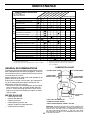
LUBRICATION CHART
dSPINDLE ZERK
dFRONT WHEEL
BEARING ZERK
cSAE 30 OR 10W30 MOTOR OIL
dGENERAL PURPOSE GREASE
eREFER TO MAINTENANCE “ENGINE” SECTION
IMPORTANT: DO NOT OIL OR GREASE THE PIVOT POINTS WHICH
HAVE SPECIAL NYLON BEARINGS. VISCOUS LU BRI CANTS WILL
ATTRACT DUST AND DIRT THAT WILL SHORT EN THE LIFE OF
THE SELF-LU BRI CAT ING BEARINGS. IF YOU FEEL THEY MUST
BE LU BRI CAT ED, USE ONLY A DRY, POW DERED GRAPHITE TYPE
LU BRI CANT SPARINGLY.
dSPINDLE ZERK
dFRONT WHEEL
BEARING ZERK
eENGINE
cGEARSHIFT
PIVOTS
GENERAL RECOMMENDATIONS
The warranty on this tractor does not cover items that have
been subjected to operator abuse or negligence. To receive
full value from the warranty, operator must main tain tractor
as instructed in this manual.
Some adjustments will need to be made periodically to
properly maintain your tractor.
At least once a season, check to see if you should make
any of the adjustments described in the Service and
Adjustments section of this manual.
• At least once a year you should replace the spark plug,
clean or replace air fi lter, and check blades and belts
for wear. A new spark plug and clean air fi lter assure
proper air-fuel mixture and help your engine run better
and last longer.
BEFORE EACH USE
• Check engine oil level.
• Check brake operation.
• Check tire pressure.
• Check operator presence and
interlock systems for proper operation.
• Check for loose fasteners.

15
MAINTENANCE
FIG. 9
FIG. 8
BATTERY
Your tractor has a battery charging system which is suf fi cient
for normal use. However, periodic charging of the battery
with an automotive charger will extend its life.
• Keep battery and terminals clean.
• Keep battery bolts tight.
• Keep small vent holes open.
• Recharge at 6-10 amperes for 1 hour.
NOTE: The original equipment battery on your tractor is
maintenance free. Do not attempt to open or remove caps
or covers. Adding or checking level of electrolyte is not
nec es sary.
TRACTOR
Always observe safety rules when performing any main-
te nance.
BRAKE OPERATION
If tractor requires more than six (6) feet stopping distance
at high speed in highest gear, then brake must be adjusted.
(See “TO ADJUST BRAKE” in the Service and Ad just ments
section of this manual).
TIRES
• Maintain proper air pressure in all tires (See “PROD UCT
SPECIFICATIONS” section of this man ual).
• Keep tires free of gasoline, oil, or insect control chemi-
cals which can harm rubber.
• Avoid stumps, stones, deep ruts, sharp objects and
other hazards that may cause tire damage.
NOTE: To seal tire punctures and prevent fl at tires due to
slow leaks, tire sealant may be purchased from your local
parts dealer. Tire sealant also prevents tire dry rot and
corrosion.
OPERATOR PRESENCE SYSTEM
Be sure operator presence and interlock sys tems are work-
ing properly. If your tractor does not function as described,
repair the problem immediately.
• The engine should not start unless the clutch/brake
pedal is fully depressed and attachement clutch control
is in the disengaged position.
• When the engine is running, any attempt by the op er a tor
to leave the seat without fi rst setting the parking brake
should shut off the engine.
• When the engine is running and the at tach ment clutch
is engaged, any attempt by the operator to leave the
seat should shut off the engine.
• The attachment clutch should never operate unless
the operator is in the seat.
BLADE CARE
For best results mower blades must be kept sharp. Re place
bent or damaged blades.
5/8" BOLT
OR PIN
BLADE
CENTER HOLE
TO SHARPEN BLADE (See Fig. 9)
NOTE: We do not recommend sharpening blade - but if
you do, be sure the blade is balanced.
Care should be taken to keep the blade balanced. An un-
bal anced blade will cause excessive vibration and even tual
dam age to mower and engine.
• The blade can be sharpened with a fi le or on a grind-
ing wheel. Do not attempt to sharpen while on the
mower.
• To check blade balance, you will need a 5/8" diameter
steel bolt, pin, or a cone balancer. (When using a
cone balancer, follow the instructions supplied with
bal anc er.)
NOTE: Do not use a nail for balancing blade. The lobes of
the center hole may appear to be centered, but are not.
• Slide blade on to an unthreaded portion of the steel bolt
or pin and hold the bolt or pin parallel with the ground.
If blade is balanced, it should remain in a horizontal
position. If either end of the blade moves downward,
sharpen the heavy end until the blade is balanced.
MANDREL
ASSEMBLY
BLADE
TRAILING
EDGE UP
LOCK WASHER
BLADE BOLT
BLADE REMOVAL (See Fig. 8)
• Raise mower to highest position to allow access to
blades.
• Remove blade bolt, lock washer and fl at washer se cur ing
blade.
• Install new or resharpened blade with trailing edge up
towards deck as shown.
IMPORTANT: TO ENSURE PROPER ASSEMBLY, CENTER
HOLE IN BLADE MUST ALIGN WITH STAR ON MANDREL
ASSEMBLY.
• Reassemble blade bolt, lock washer and fl at washer
in exact order as shown.
• Tight en blade bolt se cure ly (27-35 Ft. Lbs. torque).
IMPORTANT: BLADE BOLT IS HEAT TREATED. IF BOLT NEEDS
REPLACING, REPLACE ONLY WITH APPROVE BOLT SHOWN
IN THE REPAIR PARTS.
FLAT WASHER
CENTER
HOLE
STAR

16
MAINTENANCE
V-BELTS
Check V-belts for deterioration and wear after 100 hours and
replace if necessary. The belts are not adjustable. Re place
belts if they begin to slip from wear.
TRANSAXLE COOLING
Keep transaxle free from build-up of dirt and chaff which
can restrict cooling.
FIG. 11
FIG. 10
TO CLEAN BATTERY AND TERMINALS
Corrosion and dirt on the battery and terminals can cause
the battery to “leak” power.
• Disconnect BLACK battery cable fi rst then RED bat-
tery cable and remove battery from tractor.
• Rinse the battery with plain water and dry.
• Clean terminals and battery cable ends with wire brush
until bright.
• Coat terminals with grease or petroleum jelly.
• Reinstall battery (See “REPLACING BATTERY” in the
Service and Adjustment sec tion of this manual).
0
2
4
63
CLOSED
AND
LOCKED
POSITION
DRAIN
TUBE
OIL DRAIN VALVE
TO CHANGE ENGINE OIL (See Figs. 10 and 11)
Determine temperature range expected before oil change.
All oil must meet API service classifi cation SF-SJ.
• Be sure tractor is on level surface.
• Oil will drain more freely when warm.
• Catch oil in a suitable container.
• Remove oil fi ll cap/dipstick. Be careful not to allow dirt
to enter the engine when changing oil.
• Remove yellow cap from end of drain valve and install
the drain tube onto the fi tting.
YEL LOW CAP
ENGINE
LUBRICATION
Only use high quality detergent oil rated with API service
classifi cation SF-SJ. Select the oil’s SAE viscosity grade
according to your expected operating temperature.
TEMPERATURE RANGE ANTICIPATED BEFORE NEXT OIL CHANGE
SAE VISCOSITY GRADES
-20 0 30 40
80
100
-30
-20 0
20 30 40
F
C
32
-10
10
60
5W-30
SAE 30
oil_visc_chart1_e
NOTE: Although multi-viscosity oils (5W30, 10W30 etc.)
improve starting in cold weather, these multi-viscosity oils
will result in increased oil consumption when used above
32°F. Check your engine oil level more frequently to avoid
possible engine damage from running low on oil.
Change the oil after every 25 hours of operation or at least
once a year if the tractor is not used for 25 hours in one
year.
Check the crankcase oil level before starting the engine
and after each eight (8) hours of operation. Tighten oil fi ll
cap/dipstick securely each time you check the oil level.
CLEAN AIR SCREEN
Air screen must be kept free of dirt and chaff to prevent
engine dam age from overheating. Clean with a wire brush
or com pressed air to re move dirt and stubborn dried gum
fi bers.
• Unlock drain valve by pushing inward and turning
coun ter clock wise.
• To open, pull out on the drain valve.
• After oil has drained completely, close and lock the
drain valve by pushing inward and turning clockwise
until the pin is in the locked position as shown.
• Remove the drain tube and replace the cap onto to the
bottom fi tting of the drain valve.
• Refi ll engine with oil through oil fi ll dipstick tube. Pour
slowly. Do not overfi ll. For approximate capacity see
“PRODUCT SPECIFICATIONS” section of this man-
u al.
• Use gauge on oil fi ll cap/dipstick for checking level.
Be sure dipstick cap is tightened securely for accurate
reading. Keep oil at “FULL” line on dipstick. Tighten cap
onto the tube securely when fi nished.

17
MAINTENANCE
CLEANING
• Clean engine, battery, seat, fi nish, etc. of all foreign
matter.
• Keep fi nished surfaces and wheels free of all gasoline,
oil, etc.
• Protect painted surfaces with automotive type wax.
We do not recommend using a garden hose or pressure
washer to clean your tractor unless the engine and trans-
mission are covered to keep water out. Water in engine or
transmission will shorten the useful life of your tractor. Use
compressed air or a leaf blower to remove grass, leaves
and trash from tractor and mower.
IN-LINE FUEL FILTER (See Fig. 12)
The fuel fi lter should be replaced once each season. If fuel
fi lter becomes clogged, ob struct ing fuel fl ow to car bu re tor,
re place ment is re quired.
• With engine cool, remove fi lter and plug fuel line sec-
tions.
• Place new fuel fi lter in position in fuel line with arrow
pointing towards carburetor.
• Be sure there are no fuel line leaks and clamps are
properly positioned.
• Immediately wipe up any spilled gasoline.
00667
FIG. 12
FUEL
FILTER
CLAMP
CLAMP
MUFFLER
Inspect and replace corroded muffl er and spark arrester
(if equipped) as it could create a fi re hazard and/or dam-
age.
SPARK PLUGS
Replace spark plugs at the beginning of each mowing sea-
son or after every 100 hours of use, whichever comes fi rst.
Spark plug type and gap setting is shown in "PROD UCT
SPECIFICATIONS" section of this manual.
AIR FILTER
Your engine will not run properly using a dirty air fi lter.
Service air cleaner more often under dusty conditions. See
Engine Manual.
CLEAN AIR INTAKE/COOLING AREAS
To insure proper cooling, make sure the grass screen,
cooling fi ns, and other external surfaces of the engine are
kept clean at all times.
Every 100 hours of operation (more often under extremely
dusty, dirty conditions), remove the blower housing and
other cooling shrouds. Clean the cooling fi ns and external
surfaces as necessary. Make sure the cooling shrouds are
reinstalled.
NOTE: Operating the engine with a blocked grass screen,
dirty or plugged cooling fi ns, and/or cooling shrouds re moved
will cause engine damage due to overheating.

18
SERVICE AND ADJUSTMENTS
WARNING: TO AVOID SE RI OUS IN JU RY, BEFORE PERFORMING ANY SERVICE OR ADJUST-
MENTS:
• Depress clutch/brake pedal fully and set parking brake.
• Place gearshift lever in neutral (N) position.
• Place attachment clutch in “DISENGAGED” position.
• Turn ignition key to “STOP” and remove key.
• Make sure the blades and all moving parts have completely stopped.
• Disconnect spark plug wire from spark plug and place wire where it cannot come in contact
with plug.
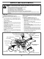
TRACTOR
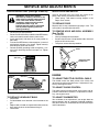
TO REMOVE MOWER (See Fig. 13)
Mower will be easier to remove from the right side of trac-
tor.
• Place attachment clutch in “DIS EN GAGED” position.
• Move attachment lift lever forward to low er mower to
its lowest po si tion.
• Roll belt off engine pulley.
• Remove small retainer spring, and remove clutch spring
off pulley bolt.
• Remove large retainer spring, slide col lar off and push
housing guide out of brack et.
• Disconnect anti-swaybar from chas sis bracket by re-
mov ing re tain er spring.
• Disconnect suspension arms from rear deck brackets
by removing retainer springs.
• Disconnect front links from deck by re mov ing retainer
springs.
• Raise lift lever to raise suspension arms. Slide mower
out from under tractor.
IMPORTANT: IF AN ATTACHMENT OTHER THAN THE MOWER
DECK IS TO BE MOUNTED ON THE TRAC TOR, REMOVE THE
FRONT LINKS AND HOOK THE CLUTCH SPRING INTO SQUARE
HOLE IN FRAME.
TO INSTALL MOWER (See Fig. 13)
• Raise attachment lift lever to its high est position.
• Slide mower under tractor with defl ector shield to right
side of tractor.
• Lower lift lever to its lowest po si tion.
• Connect front links to mower deck and secure with
retainer springs..
• Connect suspension arms to rear deck brackets and
secure with retainer springs.
• Connect anti-swaybar to chassis bracket and secure
with retainer spring.
• Push clutch cable housing guide into bracket, slide col-
lar onto guide and secure with large retainer spring.
• Place fl at washer and clutch spring on idler pulley bolt
and secure with small retainer spring.
• Install belt onto engine pulley.
02696
SUSPENSION
ARMS
RETAINER SPRINGS
(BOTH SIDES)
RETAINER SPRING
ANTI-SWAY BAR
HOUSING GUIDE
FRONT LINK
COLLAR
ENGINE PULLEY
LARGE
RETAINER
SPRING
CLUTCH SPRING
SMALL RETAINER SPRING
BRACKET
SQUARE HOLE
FIG. 13
DEFLECTOR SHIELD
SMALL RETAINER SPRING
CLUTCH SPRING
FLAT WASHER

19
SERVICE AND ADJUSTMENTS
FRONT-TO-BACK ADJUSTMENT (See Figs. 16 and 17)
IMPORTANT: DECK MUST BE LEVEL SIDE-TO-SIDE. IF THE
FOLLOWING FRONT-TO-BACK ADJUSTMENT IS NECESSARY,
BE SURE TO AD JUST BOTH FRONT LINKS EQUAL LY S O
MOWER WILL STAY LEVEL SIDE-TO-SIDE.
To obtain the best cutting results, the mower housing
should be adjusted so that the front is approximately 1/8"
to 1/2" lower than the rear when the mower is in its high-
est position.
Check adjustment on right side of tractor. Measure dis tance
“D” directly in front and behind the mandrel at bottom edge
of mower housing as shown.
• Before making any necessary adjustments, check that
both front links are equal in length.
• If links are not equal in length, adjust one link to same
length as other link.
• To lower front of mower loosen nut “E” on both front
links an equal number of turns.
• When distance “D” is 1/8" to 1/2" lower at front than
rear, tighten nuts “F” against trunnion on both front
links.
• To raise front of mower, loosen nut “F” from trunnion on
both front links. Tighten nut “E” on both front links an
equal number of turns. The two front links must remain
equal in length.
• When distance “D” is 1/8" to 1/2" lower at front than rear,
tighten nut “F” against trunnion on both front links.
• Recheck side-to-side adjustment.
FIG. 17
01267
BOTH FRONT LINKS MUST BE EQUAL IN LENGTH
FIG. 16
00598
TO LEVEL MOWER HOUSING
Adjust the mower while tractor is parked on level ground
or driveway. Make sure tires are properly infl ated (See
“PROD UCT SPECIFICATIONS” section of this manual). If
tires are over or underinfl ated, you will not properly adjust
your mower.
SIDE-TO-SIDE ADJUSTMENT (See Figs. 14 and 15)
• Raise mower to its highest position.
• At the midpoint of both sides of mower, measure height
from bot tom edge of mower to ground. Distance “A”
on both sides of mower should be the same or within
1/4" of each other.
• If adjustment is necessary, make adjustment on one
side of mower only.
• To raise one side of mower, tighten lift link ad just ment
nut on that side.
• To lower one side of mower, loosen lift link ad just ment
nut on that side.
NOTE: Each full turn of adjustment nut will change mow er
height about 1/8".
• Recheck measurements after adjusting.
BOTTOM EDGE
OF MOWER TO
GROUND
FIG. 14
FIG. 15
A
A
GROUND LINE
BOTTOM EDGE
OF MOWER TO
GROUND
01553
SUS PEN SION ARM
LIFT LINK
ADJUSTMENT NUT
01268
“D”
“D”
MAN DREL
01156
NUT “E”
TRUNNION
NUT “F”
FRONT LINKS

20
SERVICE AND ADJUSTMENTS
FIG. 18
0231
4
IDLER PULLEYS
MANDREL PULLEYS
1-1/2"
00238
FIG. 19
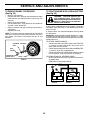
TO CHECK AND ADJUST BRAKE
(See Fig. 19)
Your tractor is equipped with an ad just able brake system
which is mounted on the right side of the transaxle.
If tractor requires more than fi ve (5) feet to stop at highest
speed in high est gear on a level, dry concrete or paved
surface, then brake must be checked and ad just ed.
TO CHECK BRAKE
• Park tractor on a level, dry concrete or paved surface,
depress clutch/brake pedal all the way down and en-
gage parking brake.
• Place gear shift lever in neutral (N) position.
The rear wheels must lock and skid when you try to manually
push the tractor forward. If the rear wheels rotate, the brake
needs to be adjusted or the pads need to be replaced.
TO ADJUST BRAKE
• Depress clutch/brake pedal all the way down and en-
gage parking brake.
• Measure distance between brake operating arm and
nut “A” on brake rod.
• If distance is other than 1-1/2", loos en jam nut and turn
nut “A” until dis tance becomes 1-1/2". Re tight en jam
nut against nut “A”.
• Road test tractor for proper stopping distance as stated
above. Readjust if nec es sary. If stopping distance is
still greater than fi ve (5) feet in high est gear, further
main te nance is nec es sary. Replace brake pads or
contact a qualifi ed service center.
JAM NUT
WITH PARKING BRAKE “ENGAGED”
OPERATING ARM
NUT “A”
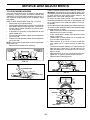
TO REPLACE MOWER BLADE DRIVE BELT
(See Fig. 18)
The mower blade drive belt may be replaced without tools.
Park the tractor on level surface. Engage parking brake.
BELT REMOVAL -
• Remove mower from tractor (See “TO REMOVE
MOW ER” in this section of this manual).
• Work belt off both mandrel pulleys and idler pulleys.
• Pull belt away from mower.
BELT INSTALLATION -
• Install new belt in reverse order of removal.
• Make sure belt is in all pulley grooves and in side all
belt guides.
• Install mower in reverse order of removal instruc-
tions.
Page is loading ...
Page is loading ...
Page is loading ...
Page is loading ...
Page is loading ...
Page is loading ...
Page is loading ...
Page is loading ...
-
 1
1
-
 2
2
-
 3
3
-
 4
4
-
 5
5
-
 6
6
-
 7
7
-
 8
8
-
 9
9
-
 10
10
-
 11
11
-
 12
12
-
 13
13
-
 14
14
-
 15
15
-
 16
16
-
 17
17
-
 18
18
-
 19
19
-
 20
20
-
 21
21
-
 22
22
-
 23
23
-
 24
24
-
 25
25
-
 26
26
-
 27
27
-
 28
28


Ask a question and I''ll find the answer in the document
Finding information in a document is now easier with AI