Page is loading ...

CELESTRON CI-700 / CM-1100 / CM-1400
INSTRUCTION MANUAL
Models #91525 / #11055 / #11065

ii • Table of Contents
The Celestron CM-1100/1400
Copyright © 1998
Celestron International
2835 Columbia Street
Torrance, CA 90503
(310) 328-9560
No part of this manual may be reproduced in any form or by any means, electronic or mechanical, including photocopy-
ing, recording, or by any information storage and retrieval system, without written permission from Celestron Interna-
tional.
Celestron International provides this manual “as is” without warranty of any kind, either expressed or implied, including
but not limited to the implied warranties of merchantability and fitness for a particular purpose. Celestron may make
modifications to this manual and/or the products described herein at any time without notice or obligation.

Table of Contents • iii
▲▲
▲▲
▲ INTRODUCTION .................................................................................................................................. 1
How to Use this Manual..................................................................................................................... 2
A Word of Caution ............................................................................................................................. 2
The Schmidt-Cassegrain Optical System .......................................................................................... 3
▲▲
▲▲
▲ ASSEMBLING YOUR CELESTRON CM-1100 ...................................................................................... 4
Unpacking Your Celestron CM-1100 .................................................................................................. 4
Setting Up the Tripod ......................................................................................................................... 6
Attaching the Center Leg Brace........................................................................................................ 7
Attaching the Central Column ............................................................................................................ 7
Attaching the Equatorial Mount.......................................................................................................... 8
Installing the Counterweight Bar ........................................................................................................ 9
Installing the Counterweight ............................................................................................................... 9
Attaching the Celestron CM-1100 to the Mount ................................................................................10
Attaching the Visual Back ................................................................................................................11
Installing the Star Diagonal ...............................................................................................................11
Installing the Eyepiece .....................................................................................................................12
Installing the Finder ..........................................................................................................................13
Installing the Polar Axis Finder .........................................................................................................14
Moving the Telescope in R.A. and DEC ............................................................................................15
Using the Slow Motion Controls........................................................................................................15
Adjusting the Mount .........................................................................................................................16
Balancing the Mount in R.A. .............................................................................................................17
Balancing the Mount in DEC.............................................................................................................18
Transporting Your Celestron CM-1100 ..............................................................................................19
Storing Your Celestron CM-1100 ......................................................................................................19
Technical Specifications ...................................................................................................................20
▲ ▲
▲ ▲
▲ TELESCOPE BASICS .........................................................................................................................22
Image Orientation .............................................................................................................................22
Focusing ..........................................................................................................................................23
General Photography Hints...............................................................................................................24
Aligning the Finder ............................................................................................................................24
Your First Look.................................................................................................................................25
Daytime Observing .....................................................................................................................25
Nighttime Observing ...................................................................................................................26
Calculating Magnification ..................................................................................................................27
Determining Field of View .................................................................................................................27
▲ ▲
▲ ▲
▲ ASTRONOMY BASICS .......................................................................................................................28
The Celestial Coordinate System ......................................................................................................28
Motion of the Stars ...........................................................................................................................29
Polar Alignment ................................................................................................................................30
Finding the Pole ...............................................................................................................................31
Latitude Scales ..........................................................................................................................32
Pointing at Polaris......................................................................................................................33
The Polar Axis Finder.................................................................................................................34
Declination Drift..........................................................................................................................35
Aligning the Setting Circles .............................................................................................................36
T A B L E O F C O N T E N T S

iv • Table of Contents
▲ ▲
▲ ▲
▲ USING THE DRIVE .............................................................................................................................37
Powering Up the Drive ......................................................................................................................37
Guide Speed ....................................................................................................................................38
Tracking Rate Selection....................................................................................................................38
BC -Backlash Correction ..................................................................................................................39
Periodic Error Correction ..................................................................................................................39
HC/CCD ...........................................................................................................................................40
12 V DC ...........................................................................................................................................40
Northern/Southern Hemisphere Operation.........................................................................................41
Using the Hand Controller.................................................................................................................41
R.A./DEC Reverse............................................................................................................................42
Autoguiding ......................................................................................................................................42
▲ ▲
▲ ▲
▲ CELESTIAL OBSERVING ...................................................................................................................43
Observing the Moon ..........................................................................................................................43
Observing the Planets ......................................................................................................................43
Observing the Sun ............................................................................................................................44
Observing Deep-Sky Objects............................................................................................................45
Using the Setting Circles ...........................................................................................................45
Star Hopping ..............................................................................................................................46
Viewing Conditions ...........................................................................................................................48
Transparency .............................................................................................................................48
Sky Illumination .........................................................................................................................48
Seeing .......................................................................................................................................48
▲ ▲
▲ ▲
▲ CELESTIAL PHOTOGRAPHY.............................................................................................................50
Short Exposure Prime Focus ...........................................................................................................51
Piggyback ........................................................................................................................................53
Eyepiece Projection .........................................................................................................................55
Long Exposure Prime Focus ............................................................................................................57
CCD Imaging ....................................................................................................................................59
Description of F-Numbers............................................................................................................60
Fastar Configuration ...................................................................................................................60
Imaging at f/2.1 ..........................................................................................................................61
Imaging at f/7 .............................................................................................................................61
Imaging at f/11 ...........................................................................................................................61
Imaging at f/22 ...........................................................................................................................62
▲ ▲
▲ ▲
▲ TELESCOPE MAINTENANCE .............................................................................................................63
Care and Cleaning of the Optics .......................................................................................................63
Collimation .......................................................................................................................................63
▲▲
▲▲
▲ OPTIONAL ACCESSORIES ................................................................................................................66
▲▲
▲▲
▲ THE MESSIER CATALOG ..................................................................................................................70
▲ ▲
▲ ▲
▲ LIST OF BRIGHT STARS ...................................................................................................................73
▲ ▲
▲ ▲
▲ FOR FURTHER READING ...................................................................................................................74

Introduction • 1
INTRODUCTION
Welcome to the Celestron world of amateur astronomy! For more than a
quarter of a century, Celestron has provided amateur astronomers with the
tools needed to explore the universe. The Celestron CM-1100 and CM-1400
continues in this proud tradition combining large aperture optics with ease of
use and portability. With a mirror diameter of 11 inches, your Celestron CM-
1100 has a light gathering power of 1,593 times that of the unaided human eye,
and the CM-1400 has a light gathering power of 2,581 times that of the unaided
human eye. Yet despite their large apertures, the Celestron CM-1100 and CM-
1400 optical systems are extremely compact and portable because they utilize
the Schmidt-Cassegrain design. This means you can take your Celestron CM-
1100 or CM-1400 to the mountains or desert or wherever you observe.
The Celestron CM-1100 and CM-1400 are made of the highest quality materials
to ensure stability and durability. All this adds up to telescopes that will give
you a lifetime of pleasure with a minimal amount of maintenance. And, your
Celestron CM-1100 and CM-1400 are versatile — they grow as your interest
in astronomy grows.
Your Celestron CM-1100 and CM-1400, are not limited to astronomical viewing
alone. They can also be used for terrestrial viewing to study the world around
you. All you need to do is take the time to familiarize yourself with your
Celestron telescope and its operation.
NOTE
The CM-1100 and CM-1400 share the same mount and are basically the
same with the exception of the larger aperture of the 14". So, this
manual will basically discuss the CM-1100 but will discuss the CM-1400
when there are differences. Users of the CI-700 mount by itself will find
complete assembly and operation instructions in the "AssemblingYour
CM-1100" and "Using the Drive" sections of this manual.

2 • Introduction
This manual is designed to instruct you in the proper use of your Celestron
CM-1100 telescope. The instructions are for assembly, initial use, long term
operation, and maintenance. There are seven major sections to the manual.
The first section covers the proper procedure for setting up your Celestron CM-
1100 telescope. This includes setting up the tripod, attaching the telescope to
the mount, balancing the telescope, etc.
The second section deals with the basics of telescope use. Topics include
focusing, aligning the finder, and taking your first look. The third section
deals with the basics of astronomy which includes the celestial coordinate
system, the motion of the stars, and polar alignment. The fourth section deals
with celestial observing covering visual observations of the planets and deep-
sky objects. Using both the setting circles and star hopping are discussed.
The fifth section covers celestial photography working from the easiest to the
most difficult. The last major section is on telescope maintenance, specifically
on cleaning and collimation. Keeping your CM-1100 in proper collimation
is the single most important thing you can do to ensure it performs well.
In addition to the major sections mentioned previously, there is a list of optional
accessories for your Celestron CM-1100 that include a brief description of its
purpose. This is the section to consult when you’ve mastered the basics and
are ready for new, more challenging observations. The final part of this manual
contains a list of objects that can be observed through your Celestron CM-1100
telescope. Included are the coordinates for each object, its brightness, and a
code which indicates what type of an object it is. In addition, there is a list of
bright stars used for aligning the setting circles.
Read the assembly instructions through completely before you attempt to set
up your Celestron CM-1100 telescope. Then, once you’ve set up your
Celestron CM-1100, read the section on “Telescope Basics” before you take it
outside and use it. This will ensure that you are familiar with your telescope
before you try to use it under a dark sky. Since it will take a few observing
sessions to familiarize yourself with your Celestron CM-1100, you should keep
this manual handy until you have fully mastered your telescope’s operation.
After that, save the manual for future reference.
Your Celestron CM-1100 is designed to give you hours of fun and rewarding
observations. There are, however, a few things to consider before using your
telescope that will ensure your safety and protect your equipment.
WARNING ! NEVER LOOK DIRECTLY AT THE SUN WITH THE NAKED EYE OR WITH A
TELESCOPE. PERMANENT AND IRREVERSIBLE EYE DAMAGE MAY
RESULT.
NEVER USE YOUR TELESCOPE TO PROJECT AN IMAGE OF THE SUN
ONTO ANY SURFACE. INTERNAL HEAT BUILD-UP CAN DAMAGE THE
TELESCOPE AND/OR ANY ACCESSORIES ATTACHED TO IT.
NEVER USE AN EYEPIECE SOLAR FILTER OR A HERSCHEL WEDGE.
INTERNAL HEAT BUILD-UP INSIDE THE TELESCOPE CAN CAUSE THESE
DEVICES TO CRACK OR BREAK, ALLOWING UNFILTERED SUNLIGHT TO
PASS THROUGH TO THE EYE.
NEVER LEAVE THE TELESCOPE UNSUPERVISED, EITHER WHEN CHIL-
How to Use This
Manual
A Word of Caution

Introduction • 3
DREN ARE PRESENT OR ADULTS WHO MAY NOT BE FAMILIAR WITH
THE CORRECT OPERATING PROCEDURES OF YOUR TELESCOPE.
NEVER POINT YOUR TELESCOPE AT THE SUN UNLESS YOU HAVE THE
PROPER SOLAR FILTER. WHEN USING YOUR TELESCOPE WITH THE
CORRECT SOLAR FILTER, ALWAYS COVER THE FINDER. ALTHOUGH
SMALL IN APERTURE, THIS INSTRUMENT HAS ENOUGH LIGHT GATHER-
ING POWER TO CAUSE PERMANENT AND IRREVERSIBLE EYE DAMAGE.
IN ADDITION, THE IMAGE PROJECTED BY THE FINDER IS HOT ENOUGH
TO BURN SKIN OR CLOTHING.
A telescope is nothing more than an instrument that collects and focuses light.
The nature of the optical design determines how the light is focused. Some
telescopes, known as refractors, use lenses while others, known as reflectors,
use mirrors. The Schmidt-Cassegrain optical (or Schmidt-Cass for short)
system uses a combination of mirrors and lenses and is referred to as a
compound or catadioptric telescope. This unique design offers large diameter
optics while maintaining very short tube lengths, making them extremely
portable. This makes them extremely popular among amateur astronomers.
The Schmidt-Cassegrain system consists of a zero power corrector plate, a
spherical primary mirror, and a secondary mirror. Once light rays enter the
optical system, they travel the length of the optical tube three times.
Inside the optical tube you will notice a black tube (not illustrated) that extends
out from the center hole in the primary mirror. This is the primary baffle tube
which prevents stray light from passing through to the eyepiece or camera
without striking the primary or secondary mirrors.
Figure 1-1
This cross-sectional diagram shows the light path of the Schmidt-Cassegrain optical
system. Note that the light rays travel the length of the telescope tube three times,
making this a compact optical design. Note that the curve of the corrector plate is
greatly exaggerated.
The Schmidt-Cassegrain
Optical System

4 • Assembling Your CM-1100
ASSEMBLING YOUR CM-1100
This section covers the assembly instructions for your Celestron CM-1100
telescope. The Celestron CM-1100 should be set up indoors the first time so
that it is easy to identify the various parts and familiarize yourself with the
correct assembly procedure before attempting it outdoors.
The Celestron CM-1100 is a standard 11" Schmidt-Cassegrain telescope on a
heavy-duty German equatorial mount. The Celestron CM-1100 comes stan-
dard with Starbright ™ enhanced multilayer aluminum coatings on the primary
and secondary mirrors for increased reflectivity. Also, the corrector plate is
fully coated to allow maximum light transmission. The Celestron CM-1100 is
shipped in six boxes. One contains the telescope and is accompanied by a
box that contains most of the standard accessories, which are:
• 26mm Plössl Ocular 1-1/4"
• Visual Back 1-1/4" (2" Visual Back on the CM-1400)
• Star Diagonal 1-1/4" (2" Mirror Diagonal for the CM-1400)
• 9x50mm Finderscope with Bracket
• Car Battery Adapter
• Lens Cap
In separate boxes are the following:
• Optical Tube Assembly
• Equatorial Mount and Counterweight Bar
• Tripod
• Central Column, Electronics Module, Polar Axis Finder and Hand Control
• One 23 Pound Counterweight (The CM-1400 come with two 25 lb.
counterweights)
• Accessories for Optical Tube
Included is all the hardware needed to assemble the telescope.
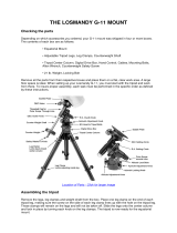
Use the diagram on the following page (see Figure 2-1) to familiarize yourself
with the various parts of your Celestron CM-1100 telescope.
Remove all the pieces from their respective boxes and place on a flat, clear
work area. A large floor space is ideal. When setting up your Celestron CM-
1100) you must start with the tripod and work up from there. These instruc-
tions are laid out in the order each task must be performed.
Unpacking Your
Celestron CM-1100

Assembling Your CM-1100 • 5
Figure 2-1
1. Optical Tube
2. Finderscope
3. Star Diagonal
4. Eyepiece
5. Polar Axis Finderscope
6. Drive Control Electronics
7. Hand Control
8. Tripod
9. Center Leg Brace
10. Counterweight
11. Counterweight Bar
12. R.A. Clutch Knob
13. DEC Clutch Knob
14. Mounting Platform Clamp Knob
15. Dovetail Slidebar
16. Objective Lens Cover
1
2
11
7
8
3
5
4
9
6
10
12
13
14
15
16
CM-1100

6 • Assembling Your CM-1100
Setting Up the Tripod
The tripod legs attach to a central column which together form the tripod to
which the equatorial mount attaches. The tripod comes with two leg support
brackets; a collapsible one that is already attached to the lower legs and a
removable one that must be attached. To set up the tripod:
1. Stand the tripod vertically on a level surface, with the feet facing down (See
Figure 2-2).
2. Grab the lower portion of two of the tripod legs and lift them slightly off the
ground so that the tripod is resting on the third leg.
3. Extend the tripod legs by pulling the tripod legs apart until the collapsible
leg bracket is fully extended. (See Figure 2-3)
Before the tripod is ready to support the equatorial head and optical tube the
center leg support brace must first be installed.
Figure 2-2
Figure 2-3

Assembling Your CM-1100 • 7
Before the equatorial mount head can be installed, the central column with
the electronics module must be attached to the tripod. To attach the central
column:
1 Position the central column so that the electronics module is right
side up (see Figure 2-4).
2 Place the lower end of the central column over the tripod head.
3 Rotate the column until the three holes line up with the threaded
holes on the side of the tripod head. The electronics console should
be positioned directly between two of the tripod leg hinges to provide
easy access to it even when the counterweight bar and
counterweight(s) are attached.
4 Insert the three 3/8-16 button head cap screws provided through the
holes in the central column and into the tripod head.
5 Tighten the screws to hold the column securely in place.
Attaching the Center
Leg Brace
For maximum rigidity, the CI 700 tripod has a center leg brace that installs on
to the threaded rod below the tripod head. This brace fits snugly against the
tripod legs, increasing stability while reducing vibration and flexure. To attach
the center leg brace:
1 Unscrew the tension knob from the threaded rod beneath the tripod
head.
2 Place the center leg brace onto the threaded rod so that the cup on
the end of each bracket contours to the curve of the tripod legs.
3 Rotate the tension knob back on the threaded rod until the brace is
very snug against each tripod leg.
Attaching the Central
Column
Center Leg Brace
Central Column
Electronics Console
Figure 2-4

8 • Assembling Your CM-1100
After the tripod is set up, you are ready to attach the equatorial mount. The
equatorial mount is the platform to which the telescope attaches and allows
you to move the telescope in right acsension and declination. The mount is
also adjustable so you can orient the axis of rotation so that it is parallel with
the Earth’s axis of rotation (see the section on “Polar Alignment”). To attach
the equatorial mount to the tripod:
1. Insert the base of the equatorial mount into the top of the central column.
2. Rotate the equatorial mount on the central column until the holes in the
mount line up with those in the central column and the dec opening (where
the counterweight shaft will go) is positioned directly over one of the tripod
legs.
3. Insert the three remaining 3/8-16 cap screws and washers provided through
the holes in the central pier and into the equatorial mount (see Figure 2-5).
4. Tighten the screws to hold the equatorial mount in place.
Attaching the
Equatorial Mount
Figure 2-5
Central Column
Equatorial Mount
Counterweight
Shaft Opening

Assembling Your CM-1100 • 9
To properly balance the telescope, the mount comes with a counterweight bar
and one counterweight (the CM-1400 comes with two counterweights). The
counterweight bar is located in the same box as the Equatorial Mount Head —
in a cutout along the bottom of the shipping box. To install the counterweight
bar:
1. Locate the opening in the equatorial mount on the DEC axis (see figure 2-
6). It is opposite the telescope mounting platform.
2. Thread the counterweight bar into the opening until tight.
Once the bar is securely in place you are ready to attach the counterweight.
Since the fully assembled telescope is quite heavy, position the mount
so that the tripod leg with the counterweight bar over it is pointing
towards north before the tube assembly and counterweights are at-
tached. This will make the polar alignment procedure much easier.
The Celestron CM-1100 comes standard with one 23 pound counterweight. The
CM-1400 comes with two 25 pound counterweights. To install the
counterweight(s):
1. Orient the mount so that the counterweight bar points toward the ground
(see figure 2-7).
2. Remove the counterweight safety thumbscrew and washer on the end of
the counterweight bar (i.e., opposite the end that attaches to the mount).
3. Loosen the set screw on the side of the counterweight.
4. Slide the counterweight onto the shaft.
5. Tighten the locking screw on the side of the weight to hold the counter-
weight in place.
6. Replace the counterweight safety thumbscrew and washer.
Installing the
Counterweight Bar
Installing the
Counterweight
HINT
Figure 2-5
Counterweight
Bar
Counterweight Bar
Safety Screw
Figure 2-6
Counterweight
Bar
Counterweight
Figure 2-7

10 • Assembling Your CM-1100
The telescope attaches to the mount via a dovetail slide bar which is mounted
along the bottom of the telescope. Before you attach the optical tube, make
sure that the declination and right ascension clutch knobs are tight. This will
ensure that the mount does not move suddenly while attaching the telescope.
To mount the telescope tube:
1 Loosen the knobs on the side of the telescope mounting platform. This
allows you to slide the dovetail bar on the telescope onto the mount.
2 Slide the dovetail bar on the telescope tube into the mounting platform of
the mount. Slide the telescope so that the back of the dovetail bar is
almost flush with the back of the mounting platform.
3 Tighten the locking knobs on the side of the mounting platform to hold the
telescope in place.
4 Slide the dovetail slide bar safety clamp down the front end of the slide bar
until it touches the mounting platform. This clamp is designed to keep the
telescope from sliding off the mount in case the knobs on the side of the
platform comes loose. It is best to wait until the telescope is balanced in
R.A. and DEC before attaching the safety clamp (see "Balancing the
Mount in DEC" later in this section).
Attaching the Optical
Tube to the Mount
Figure 2-8
Optical Tube
Dovetail Slide Bar
Mounting Platform
Mounting Platform
Locking Knobs

Assembling Your CM-1100 • 11
The visual back is the accessory that allows you to attach all visual accesso-
ries to the telescope. To attach the visual back:
1. Remove the plastic cover on the rear cell.
2. Place the knurled slip ring on the visual back over the threads on the rear
cell.
3. Hold the visual back with the set screw in a convenient position and rotate
the knurled slip ring clockwise until tight.
Once this is done, you are ready to attach other accessories, such as eye-
pieces, diagonal prisms, etc.
If you want to remove the visual back, rotate the slip ring counterclockwise until
it separates from the rear cell.
The star diagonal is a prism that diverts the light at a right angle to the light
path of the telescope. This allows you to observe in positions that are physi-
cally more comfortable than if you looked straight through. To attach the star
diagonal: NOTE: The CM-1400 uses a 2" mirror diagonal.
1. Turn the set screw on the visual back until its tip no longer extends into
(i.e., obstructs) the inner diameter of the visual back.
2. Slide the chrome portion of the star diagonal into the visual back.
3. Tighten the set screw on the visual back to hold the star diagonal in place.
If you wish to change the orientation of the star diagonal, loosen the set screw
on the visual back until the star diagonal rotates freely. Rotate the diagonal to
the desired position and tighten the set screw.
Attaching the Visual
Back
Installing the Star
Diagonal
Figure 2-9

12 • Assembling Your CM-1100
The eyepiece, or ocular, is an optical element that magnifies the image
focused by the telescope. The ocular(s) fit into either the visual back directly,
the star diagonal, or the Erect Image Diagonal (purchased separately). To
install an ocular:
1. Loosen the set screw on the star diagonal until the tip no longer extends
into the inner diameter of the eyepiece end of the diagonal.
2. Slide the chrome portion of the eyepiece into the star diagonal.
3. Tighten the set screw on the star diagonal to hold the eyepiece in place.
To remove the eyepiece, loosen the set screw on the star diagonal and slide
the eyepiece out. You can replace it with another ocular (purchased sepa-
rately).
NOTE: NOTE:
NOTE: NOTE:
NOTE: The 2" mirror diagonal has a 1 1/4" eyepiece adapter to use 1 1/4"
eyepieces. You may remove the adapter to use 2" eyepieces.
Eyepieces are commonly referred to by focal length and barrel diameter. The
focal length of each eyepiece is printed on the eyepiece barrel. The longer the
focal length (i.e., the larger the number) the lower the eyepiece power and the
shorter the focal length (i.e., the smaller the number) the higher the magnifica-
tion. Generally, you will use low-to-moderate power when viewing. For more
information on how to determine power, see the section on “Calculating
Magnification.”
Installing the EyepieceInstalling the Eyepiece
Installing the EyepieceInstalling the Eyepiece
Installing the Eyepiece
Figure 2-10Figure 2-10
Figure 2-10Figure 2-10
Figure 2-10

Assembling Your CM-1100 • 13
The CM-1100 telescope come with a 9x50 finderscope used to help you locate
and center objects in the main field of your telescope. To accomplish this, the
finder has a built-in cross-hair reticle that shows the optical center of the
finderscope.
Start by removing the finder and hardware from the plastic wrapper. Included
are the following:
• 9x50mm Finder
• Finder Bracket
• Rubber O-ring
• Three Nylon Tipped Thumbscrews (10-24x1/2")
• Two Allen Head Screws (8-32x1/2")
To install the finder:
1. Attach the bracket to the optical tube. To do this, place the curved portion
of the bracket with the slot over the two holes in the rear cell. The bracket
should be oriented so that the rings that hold the finder are over the
telescope tube, not the rear cell (see Figure 2-1). Start threading the
screws in by hand and tighten fully with an Allen wrench.
2. Partially thread-in the three nylon-tipped thumbscrews that hold the finder
in place inside the bracket. Tighten the screws until the nylon heads are
flush with the inner diameter of the bracket ring. Do
NOTNOT
NOTNOT
NOT thread them in
completely or they will interfere with the placement of the finder. (Having
the screws in place when the finder is installed will be easier than trying to
insert the screws after the finder has been installed.)
3. Slide the rubber O-ring over the back of the finder (it will
NOTNOT
NOTNOT
NOT fit over the
objective end of the finder). It may need to be stretched a little. Once on
the main body of the finder, slide it up about one inch from the end of the
finder.
4. Rotate the finder until one cross hair is parallel to the R.A. axis and the
other is parallel to the DEC axis.
5. Slide the eyepiece end of the finder into the front of the bracket.
6. Slightly tighten the three nylon tipped thumbscrews on the front ring of the
bracket to hold the finder in place.
7. Once on, push the finder back until the O-ring is snug inside the back ring
of the finder bracket.
8. Hand tighten the three nylon tipped thumbscrews until snug.
Installing the FinderInstalling the Finder
Installing the FinderInstalling the Finder
Installing the Finder

14 • Assembling Your CM-1100
To aid in polar aligning the mount, your telescope comes standard with a Polar
Housing Finder. It installs directly on top of the polar housing of the mount. To
install the Polar Finder:
1. Locate the Polar Finder assembly. The Polar Finder assembly consists
of the polar finder, mounting bracket and knurled mounting screw (see
Figure 2.11).
2. Place the Polar Finder Assembly on top of the polar axis housing so that
the mounting stop on the metal bracket sits flush against the rear of the
polar housing.
3. Secure the Polar Finder Assembly to the mount by threading the Knurled
Mounting Screw into the threaded hole on top of the Polar Housing.
The Polar Axis Finder is now installed and ready to use. To learn how to polar
align the mount using the Polar Axis Finder, refer to the Astronomy Basics
section of the manual.
Installing the PolarInstalling the Polar
Installing the PolarInstalling the Polar
Installing the Polar
FinderFinder
FinderFinder
Finder
Figure 2-11
Finderscope Bracket Assembly
Knurled Mounting Screw
Polar Axis Housing
Nylon Tension Screw
Polar Finderscope
Mounting Stop

Assembling Your CM-1100 • 15
Once set up, you need to point your telescope at various portions of the sky to
observe different objects. To make rough adjustments, loosen the R.A. and
DEC clutch knobs slightly and move the telescope in the desired direction.
Both the R.A. and DEC axis have two knobs to clutch down each axis of the
telescope. To loosen the clutches on the telescope, rotate the clutch knobs
(see figure below) counterclockwise. Once your have found your desired object
in the finderscope, rotate the clutch knobs on each axis clockwise to lock the
telescope in place.
Moving the TelescopeMoving the Telescope
Moving the TelescopeMoving the Telescope
Moving the Telescope
in R.A. and DECin R.A. and DEC
in R.A. and DECin R.A. and DEC
in R.A. and DEC
Using the Slow MotionUsing the Slow Motion
Using the Slow MotionUsing the Slow Motion
Using the Slow Motion
ControlsControls
ControlsControls
Controls
The CI 700 mount is equipped with slow motion controls on both the R.A. and
Declination axis. Each slow motion control has a clutch mechanism that
allows you to override the tracking motor and adjust the amount of tension
when turning the knob. To adjust the clutch mechanism, hold the slow motion
knob with one hand, and rotate the clutch wheel with your other hand. Rotate
the clutch wheel clockwise (downward) to increase the tension on the slow
motion control and counterclockwise (upward) to decrease the tension.
DEC Clutch Knobs
R.A. Clutch Knobs
DEC Slow Motion Control
R.A. Slow Motion Control
Slow Motion Knob
Clutch Wheel
Figure 2-12
Figure 2-13

16 • Assembling Your CM-1100
In order for the clock drive to track accurately, the telescope’s axis of rotation
must be parallel to the Earth’s axis of rotation, a process known as polar
alignment. Polar alignment is achieved
NOTNOT
NOTNOT
NOT by moving the telescope in R.A.
or DEC, but by adjusting the mount vertically, which is called altitude, and
horizontally, which is called azimuth. This section simply covers the correct
movement of the telescope during the polar alignment process. The actual
process of polar alignment, that is making the telescope’s axis of rotation
parallel to the Earth’s, is described later in this manual in the section on “Polar
Alignment.”
To adjust the mount in altitude:
1. Locate the altitude adjustment bolt just above the tripod column (see
figure 2-14).
2. Using the 7/32" Allen wrench provided, turn the altitude adjustment bolt
until the mount is at the right elevation.
The total altitude range is from 13° to 65°. With the 23 lb counterweight
attached to the counterweight shaft, the equatorial head can go as low as 20°
without hitting the tripod leg.
To adjust the mount in azimuth:
1. Locate the azimuth adjustment bolt on the flat portion of the tripod column.
2. Loosen the two azimuth lock knobs located on the top of the tripod
column.
3. Turn the azimuth adjustment bolt with the 7/32" Allen wrench until the
polar axis is pointing in the right direction.
4. Tighten the azimuth lock knobs to hold the mount in place.
The mount can be moved ± 7° in azimuth using these bolts.
Keep in mind that adjusting the mount is done during the polar alignment
process only. Once polar aligned, the mount must
NOTNOT
NOTNOT
NOT be moved. Pointing
the telescope is done by moving the mount in right ascension and declination,
as described earlier in this manual. Once the appropriate adjustments have
been made and you are aligned on the celestial pole, turn the clock drive on
and the telescope will track.
Adjusting the MountAdjusting the Mount
Adjusting the MountAdjusting the Mount
Adjusting the Mount
Figure 2-14
Altitude Adjustment Bolt
Azimuth Adjustment Bolt
Bubble Level
Azimuth Lock Screws
/