Miller JK000000 Owner's manual
- Category
- Welding System
- Type
- Owner's manual
This manual is also suitable for

Millerfi
August
1990
FORM:
OM-1556A
MODEL:
MTXC
3501M
MTX
3502
MTXW
5001
ROBOT
GUNS
OWNERS
MANUAL
IMPORTANT:
Read
and
understand
the
entire
contents
of
both
this
manual
and
the
power
source
manual
used
with
this
unit,
with
special
emphasis
on
the
safety
material
throughout
both
manuals,
before
installing,
operating,
or
maintaining
this
equipment.
This
unit
and
these
Instructions
are
for
use
only
by
persons
trained
and
experienced
In
the
safe
operation
of
welding
equip
ment.
Do
not
allow
untrained
persons
to
install,
operate,
or
maintain
this
unit.
Contact
your
distributor
If
you
do
not
fully
understand
these
Instructions.
MILLER
ELECTRIC
Mfg.
Co.
ANtHer
Gr~ip
Ltd..
Con~any
P.O.
Box
1079
Appleton,
WI
54912
USA
Tel.
414-734-9821
TB-114
276
PRINTED
N
U
S.A

UI
MILLERS
TRUE
BLUETM
LIMITED
WARRANTY
Effective
January
1,
1992
(Equipment
with
a
serial
number
preface
of
KC
or
newer)
This
limited
warranty
supersedes
all
previous
MILLER
warranties
and
is
exclusive
with
no
other
guarantees
or
warranties
expressed
or
imptied.
:1~!
LIMITED
WARRANTY
Subject
to
the
terms
and
conditione
below.
MILLER
Electric
Mtg.
Co..
A~pleton.
Wisconsin,
warrants
to
its
original
retail
purchaser
that
new
MILLER
equipment
sold
aher
the
effective
date
ot
this
limited
warranty
is
free
of
de
feds
in
material
and
workmanship
at
the
time
it
is
shipped
by
MILLER.
THIS
WAR
RANTY
IS
EXPRESSLY
IN
LIEU
OF
ALL
OTHER
WARRANTIES,
EXPRESS
OR
IMPLIED,
INCLUDING
TNE
WARRANTIES
OF
MERCHANTABILITY
AND
FIT
NESS.
al
Within
the
warranty
periods
listed
below.
MILLER
will
repair
or
replace
any
war
ranted
parts
or
componenta
that
tail
due
to
such
detects
in
material
or
workmanship.
MILLER
must
be
notitied
in
writing
within
thirty
(30)
days
of
such
defector
failure,
at
which
time
MILLER
will
provide
instruct
ions
on
the
warranty
claim
procedures
lobe
followed.
MILLER
shall
honor
warranty
claims
on
warranted
equipment
listed
below
in
the
event
of
such
a
failure
within
the
warranty
lime
periods.
All
warranty
lime
periods
start
on
the
dale
that
the
equipment
was
delivered
to
the
original
retail
purchaser,
and
are
as
follows
1.
5
Years
Parts
3
Years
Labor
Original
main
power
rectifiers
2.
3
Years
Parts
and
Labor
*
Transformer/Rectifier
Power
Sources
Plasma
Arc
Culling
Power
Sources
Semi-Aatomalic
and
Automatic
Wire
Feeders
Robots
3.
2
Years
Parts
and
Labor
Engine
Driven
Welding
Generators
(NOTE.
Engines
are
warranted
separately
by
the
engine
manufacturer)
4.
1
Year
Parts
and
Labor
Motor
Driven
Guns
Process
Controllers
Water
Coolant
Syslems
HF
Units
Grids
*
Spot
Welders
Load
Banks
SOX
Transformers
*
Running
Gear/Trailers
Field
Options
(NOTE:
Field
options
are
covered
under
True
BluenM
for
the
remaining
warranty
period
Of
the
product
they
are
installed
in.
or
for
a
minimum
of
one
year
whichever
is
greater.)
5.
B
Months
Baneries
6.
90
Days
Parts
and
Labor
*
MIG
Guns/TIG
Torches
Plasma
Cuning
Torches
Remote
Controls
*
Accessory
Kits
*
Replacement
Parfa
MILLERS
True
Bluen
Umited
Warranty
shall
not
apply
to:
1.
Items
furnished
by
MILLER,
but
manufactured
by
others,
such
as
engines
or
trade
accessories.
These
items
are
covered
by
the
manufacturers
warranty,
if
any.
2.
Consumable
components;
such
aa
contact
lips.
cutting
nozzles,
conlactora
and
relays.
3.
Equipment
that
has
been
modified
by
any
party
other
than
MILLER.
or
equip
ment
that
has
been
improperly
installed,
improperly
operated
or
misused
based
upon
industry
standards.
or
equipment
which
has
not
had
reasonable
and
necessary
maintenance,
or
equipment
which
has
been
used
for
operation
outside
of
the
specifications
for
the
equipment.
MILLER
PRODUCTS
ARE
INTENDED
FOR
PURCNASE
AND
USE
BY
COMMER
CIAL/INDUSTRIAL
USERS
AND
PERSONS
TRAINED
AND
EXPERIENCED
IN
TNE USE
AND
MAINTENANCE
OF
WELDING
EQUIPMENT.
In
the
event
of
a
warranty
claim
covered
by
this
warranty.
the
exclusive
remedies
shall
be,
at
MILLERS
option:
(1)
repair;
or
(2)
replacement;
or,
where
authorized
in
writing
by
MILLER
in
appropriate
cases.
(31
the
reasonable
coal
of
repair
or
replace
ment
at
an
authorized
MILLER
service
station;
or
(4)
payment
of
or
credit
for
the
pur
chase
price
(less
reasonable
depreciation
based
upon
actual
use)
upon
return
of
the
goods
at
customera
risk
and
eapense.
MILLERS
option
of
repair
or
replacement
will
be
F.O.B.,Factory
at
Appleton,
Wiaconsin,
or
FOB.
ate
MtLLER
authorized
aer
vice
facility
as
determined
by
MILLER.
Therefore
no
compensation
or
reimburse
ment
for
transportation
costa
of
any
kind
wilt
be
allowed.
TO
TNE
EXTENT
PERMITTED
BY
LAW,
TNE
REMEDIES
PROVIDED
HEREIN
ARE
TNE
SOLE
AND
EXCLUSIVE
REMEDIES.
IN
NC
EVENT
SHALL
MILLER
BE
LIABLE
FOR
DIRECT,
INDIRECt
SPECtAL.
INCIDENTAL
OR
CONSEQUENTIAL
DAMAGES
(INCLUDING
LOSS
OF
PROFIT),
WHETHER
BASED
ON
CON
TRACT.
TORT
OR
ANY
OTHER
LEGAL
THEORY.
ANY
EXPRESS
WARRANTY
NOT
PROVIDED
HEREIN
AND
ANY
IMPLIED
WAR
RANTY.
GUARANTY OR
REPRESENTATION
AS
TO
PERFORMANCE,
AND
ANY
REMEDY
FOR
BREACH
OF
CONTRACT
TORT
OR
ANY
OTHER
LEGAL
THEORY
WHICH.
BUT
FOR
THIS
PROVISION.
MIGHT
ARISE
BY
IMPLICATION,
OPERATION
CF
LAW,
CUSTOM
OF
TRADE
DR
COURSE
OF
DEALING,
IN
CLUDING
ANY
IMPLIED
WARRANTY
OF
MERCHANTABILITY
DR
FITNESS
FOR
PARTICULAR
PURPOSE.
WITH
RESPECT
TO
ANY
AND
ALL
EOUIPMENT
FURNISHED
BY
MILLER
IS
EXCLUDED
AND
DISCLAIMED
BY
MILLER.
Some
states
in
the
U.S.A.
do
not
allow
Ilmitefiona
of
how
long
en
implied
warranty
laata.
or
the
eaclualon
of
incidental,
indirect.
special
or
conaequenlial
damages,
so
the
above
limifation
or
escluaion
may
not
apply
to
you.
This
warranty
provides
spe
cific
legal
rights,
and
ofher
rights
may
be
available,
but
may
vary
from
elate
to
elate.
In
Canada,
legislation
in
some
provinces
provides
for
certain
additional
warranties
or
remedies
other
than
as
stated
herein.
and
to
the
estent
that
they
may
not
be
waived.
the
limitations
and
esdluaiOna
sat
out
above
may
not
apply.
Thia
Limited
Warranty
provides
specific
legal
rights.
and
other
righta
may
be
available,
but
may
vary
from
province
to
province.
fi
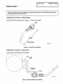
RECEIVING-HANDLING
Before
unpacking
equipment,
check
carton
for
any
damage
that
may
have
occurred
during
shipment.
File
any
claims
for
loss
or
damage
with
the
delivering
carrier.
Assistance
for
filing
or
settling
claims
may
be
obtained
from
distributor
and/or
equipment
manufacturers
Transportation
Department.
When
requesting
information
about
this
equipment,
always
provide
Model
Designation
and
Serial
or
Style
Number,
Use
the
fol)ow)ng
spaces
to
record
MDdel
Designation
and
Serial
or
Style
Number
of
your
unit,
The
information
is
located
on
the
rating
label
or
nameplate.
Model
Serial
or
Style
No,
______________________________________________
Date
of
Purchase
___________
miller
5/93

ERRATA
SHEET
After
this
manual
was
printed,
refinements
in
equipment
design
occurred.
This
sheet
lists
exceptions
to
data
appearing
later
in
this
manual.
AMENDMENT
TO
SECTION
2
SPECIFICATIONS
Amend
MTXC
3501
M
welding
gun
view
in
Figure
2-1.
Dimension
Information
AMENDMENT
TO
SECTION
3INSTALLATION
Amend
Figure
3-2.
MTXC
3501M
Gun
Installation
SB-I
35
144-A
Figure
2-1.
Dimension
Information
Axis
6
Axis
6
Mount
900
Mounting
Bracket
insulator
SB-135
148-A
Figure
3-2.
MTXC
3501
M
Gun
Installation

AMENDMENT
TO
SECTION
5
PARTS
LIST
Amend
Figure
5-2.
MTXC
3501
M
Air
Cooled
Gun
Amend
Parts
List
as
follows:
Figure
5-2.
MTXC
3501
M
Air
Cooled
Gun
14
13
..-
12
I
I
k
>
SB-135
145-A
Quantity
Replaced
With
**
Part
No.
Description
10-
10-4
132
296
133
994
143
697
143
693
MTXC-3501
M,
air
cooled
gun
NOZZLE
HOLDER
ASSEMBLY
1
10-7
133997
108776
INSULATIONBUSHING
1
10-11
133993
143692
NOZZLEASSEMBLY
1
10-12
10-13
Added
Added
143
696
143694
0-RING
(used
on
nozzle
assembly)
CLAMP,band
1
1
10-14
Added
143695
CLAMP,band
1
*~First
digit
represents
page
no
digits
following
dash
represent
item
no.
All
gun
parts
remain
the
same
with
listed
exceptions.
When
ordering
replacement
parts
refer
to
view
on
this
errata
sheet
and
Fig
5-2
in
manual
for
correct
identity
of
parts.
OM-1
556A
Page
2

OM-1
556A
-
8i~
RECEIVING-HANDLING
Before
unpacking
equipment,
check
carton
for
any
dam-
Use
the
following
spaces
to
record
the
Model
Designa
age
that
may
have
occurred
during
shipment.
File
any
tion
and
Serial
or
Style
Number
of
your
unit.
The
infor
claims
for
loss
or
damage
with
the
deliverIng
carrIer.
mation
is
located
on
the
data card
or
the
nameplate.
Assistance
for
filing
or
settling
claims
may
be
obtained
from
the
distributor
and/or
the
equipment
manufactur-
Model
________________________________
ers
Transportation
Department.
Serial
or
Style
No.
_____________________
When
requesting
information
about
this
equipment,
al
ways
provide
the
Model
Description
and
Serial
or
Style
Date
of
Purchase
______________________
Number.
TABLE
OF
CONTENTS
Section
No.
Page
No.
SECTION
1
SAFETY
PRECAUTIONS
AND
SIGNAL
WORDS
1-1.
General
Information
And
Safety
1
1-2.
Safety
Alert
Symbol
And
Signal
Words
1
SECTION
2
SPECIFICATIONS
2-1.
Duty
Cycle
1
2-2.
Description
1
SECTION
3INSTALLATION
3-1.
Gun
Preparation
2
3-2.
Outlet
Cable
Preparation
2
3-3.
MTX
3502
And
MTXW
5001
Gun
Installation
3
3-4.
MTXC
3501M
Gun
Installation
4
3-5.
Water
Connections
(Water-Cooled
Models
Only)
4
3-6.
Field
Installation
Of
Water-Cooled
Nozzle
Onto
Air-Cooled
Gun
(MTX
3502
Models
Only)
5
SECTION
4
MAINTENANCE
4-1.
Inspection
And
Upkeep
6
4-2.
Contact
Tube
Replacement
7
4-3.
Changing
Wire
Size
7
SECTION
5
PARTS
LIST
Figure
5-1.
MTX
3502
Air
Cooled
Gun
8
Figure
5-2.
MTXC-3501
Air
Cooled
Gun
10
Figure
5-3.
MTXW
5001
Water
Cooled
Gun
11
LIST
OF
CHARTS
AND
TABLES
Table
2-1.
Specifications
1


SECTION
1
SAFETY
PRECAUTIONS
AND
SIGNAL
WORDS
1-1.
GENERAL
INFORMATION
AND
SAFETY
A.
General
Information
presented
in
this
manual
and
on
various
labels,
tags,
and
plates
on
the
unit
pertainsto
equipment
design,
installation,
operation,
maintenance,
and
troubleshooting
which
should
be
read,
understood,
and
followed
for
the
safe
and
effective
use
of
this
equipment.
B.
Safety
The
installation,
operation,
maintenance,
and
troubleshooting
of
arc
welding
equipment
requires
practices
and
procedures
which
ensure
personal
safety
and
the
safety
of
others.
Therefore,
this
equipment
is
to
be
installed,
operated,
and
maintained
only
by
qualified
persons
in
accordance
with
this
manual
and
all
applicable
codes
such
as,
but
not
limited
to,
those
listed
at
the
end
of
Section
1
-
Safety
Rules
For
Operation
01
Arc
Welding
Power
Source
in
the
welding
power
source
Owners
Manual.
1-2.
SAFETY
ALERT
SYMBOL
AND
SIGNAL
WORDS
The
following
safety
alert
symbol
and
signal
words
are
used
throughout
this
manual
to
call
attention
to
and
identify
different
levels
of
hazard
and
special
instructions.
a
a
a
This
safety
alert
symbol
is
used
with
the
signal
words
WARNING
and
CAUTION
to
call
attention
to
the
safety
statements.
WARNING
statements
identify
procedures
or
practices
which
must
be
followed
to
avoid
serious
personal
injury
or
loss
of
life.
CAUTION
statements
identify
procedures
or
practices
which
must
be
followed
to
avoid
minor
personal
injury
or
damage
to
this
equipment.
IMPORTANT
statements
identify
special
instructions
necessary
for
the
most
efficient
operation
of
this
equipment.
SECTION
2
SPECIFICATIONS
Table
2-1.
SpecIficatIons
Model
Rating:
50%
Duty
Cycle
With
C02
Wire
Diameter
Capacity
Cooling
Method
Weight
Net
Ship
MTX
3502
MTXC
3501M
350
Amperes
.030-1/16
in.
(0.8
-1
.6
mm)
Air
2.3
lbs.
(1kg)
3.2
lbs.
(1.5
kg)
2.6
lbs.
(1.2kg)
3.5
lbs.
(1.6kg)
MTXW5001
500
Amperes
.045
and
1/16
in.
(1.1
and
1.6
mm)
Water
3.7
lbs.
(1.7
kg)
4.6
lbs.
(2.1
kg)
2-1.
DUTY
CYCLE
The
duty
cycle
of
a
welding
gun
is
the
percentage
of
a
ten
minute
period
that
the
gun
can
safely
be
operated
at
a
give
output
without
causing
overheating
and
damage
to
the
gun.
These
guns
are
rated
at
50%
duty
cycle
using
CO2
shielding
gas.
This
means
that
the
gun
can
be
operated
for
five
consecutive
minutes.
The
remaining
five
minutes
the
gun
should
be
idle
to
permit
proper
cooling.
CAUTION:
EXCEEDING
THE
RATED
AMPERAGE
WITH
C02
OR
FAILING
TO
REDUCE
THE
WELDING
AMPERAGE
OR
DUTY
CYCLE
WHEN
USING
MIXED
SHIELDING
GAS
can
damage
gun.
Do
not
exceed
rated
amperage
when
using
C02.
Reduce
duty
cycle
when
using
mixed
shielding
gases.
2-2.
DESCRIPTION
These
guns
are
specifically
designed
for
automatic
robotic
welding.
The
term
welding
gun
is
used
when
Gas
Metal
Arc
Welding
(GMAW)
is
done.
The
guns
are
shipped
with
the
necessary
components
for
a
specific
wire
size;
however,
through
minor
parts
changes,
each
gun
can
be
used
with
various
sizes
of
wire.
a
OM-1556
Page
1

MTX
3502
TB-114
276
SECTION
3-
INSTALLATION
a
CAUTION:
IMPROPER
ROBOTTOOL
POINT
ADJUSTMENT
can
damage
welding
gun
and
robot.
After
welding
gun
installation
is
completed,
see
Set-Up
Procedure
section
of
robot
Owners
Manual
for
tool
point
procedures.
3-1.
GUN
PREPARATION
Select
contact
tube
for
wire
size
used,
and
proceed
as
follows:
a
WARNING:
ELECTRIC
SHOCK
can
kill;
ROBOT
ARM
MOVEMENT
can
cause
serious
injury
or
death;
INCORRECT
PROCEDURES
can
cause
Injury.
Do
not
touch
live
electrical
parts.
Shut
down
welding
power
source
and
robot
control,
and
disconnect
input
power
employing
lockout/tagging
procedures.
Lockout/tagging
procedures
consist
of
removing
input
power
plug
from
receptacle,
padlocking
line
disconnect
switch(es)
in
open
position,
removing
fuses
from
fuse
box(es),
or
shutting
off
and
red-
tagging
circuit
breaker(s)
or
other
disconnecting
device(s).
MOVING
PARTS
can
cause
serious
injury.
Keep
away
from
moving
parts.
HOT
SURFACES
can
cause
severe
burns.
Allow
cooling
period
before
touching
gun.
1.
Remove
nozzle
2.
Install
desired
contact
tube
and
nozzle
onto
gun.
MTXC
3501M
TB-135
144
TB-114
276
MTXW
5001
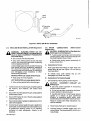
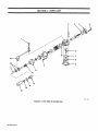
Figure
2-1.
DImension
Information
OM-1556
Page
2

MOVING
PARTS
can
cause
serious
Injury.
Keep
away
from
moving
parts.
HOT
SURFACES
can
cause
severe
burns.
Allow
cooling
period
before
touching
gun.
1.
Route
cable
through
supports
on
robot.
The
cable
connector
end
goes
to
the
wire
drive
assembly
while
the
remaining
end
goes
to
the
gun.
2.
Install
cable
connector
into
wire
drive
assembly
(see
Motor/Drive
Assembly
Owners
Manual).
3.
Slide
welding
gun
onto
liner
protruding
from
cable
until
liner
seats
inside
gun.
4.
Mark
linerflush
with
gun
body
and
slide
gun
off
liner.
5.
Measure
distance
between
mark
made
on
liner
in
Step
4
and
brass
nut
on
cable.
6.
The
liner
needs
to
be
shortened
by
the
length
measured
in
Step
5.
Cut
off
measured
length
from
end
of
liner.
3-3.
MTX
3502
AND
MTXW
5001
GUN
INSTALLA
TION
(Figure
3-1)
4A
WARNING:
ELECTRIC
SHOCK
can
kill;
ROBOT
ARM
MOVEMENT
can
cause
serious
Injury
or
death;
INCORRECT
PROCEDURES
can
cause
Injury.
Do
not
touch
live
electrical
parts.
Shut
down
welding
power
source
and
robot
control,
and
disconnect
input
power
employing
lockout/tagging
procedures.
Lockout/tagging
procedures
consist
of
removing
input
power
plug
from
receptacle,
padlocking
line
disconnect
switch(es)
in
open
position,
removing
fuses
from
fuse
box(es),
or
shutting
oft
and
red-tagging
circuit
breaker(s)
or
other
disconnecting
device(s).
MOVING
PARTS
can
cause
serIous
Injury.
Keep
away
from
moving
parts.
HOT
SURFACES
can
cause
severe
burns.
Allow
cooling
period
before
touching
gun.
IMPORTANT:
If
a
3(1
mounting
bracket
is
used,
the
bracket
must
be
installed
with
offset
to
the
right
when
viewing
the
Phi
axis
mount.
Be
sure
phenolic
insulator
is
between
gun
and
bracket.
1.
If
a
300
mounting
bracket
is
used,
secure
bracket
to
gun
using
supplied
socket
head
screws.
2.
Secure
gun
to
Phi
axis
(or
Axis
5)
mount
using
supplied
socket
head
screws
(see
Figure
3-1).
If
a
30
mounting
bracket
is
used,
secure
bracket
to
manipulator
Phi
axis
mount
using
supplied
socket
head
screws.
Slide
liner
from
outlet
cable
into
gun.
Secure
outlet
cable
to
adapter
by
tightening
nut
from
cable
onto
adapter.
5.
Connect
touch
sensor
leads
from
gun
to
leads
from
outlet
cable.
Connect
leads
from
outlet
cable
to
cord
at
gas/current
sensing
control
or
to
matching
connector
at
robot
manipulator.
Polarity
is
not
important.
Gun
Mounting
Plate
Air-Cooled
Gun
Shown
FIgure
3-1.
MTX
3502
And
MTXW
5001
Gun
Installation
3.
4.
Phi
Axis
(Axis
5)
Phi
Axis
(Axis
5)
Mount
(Phenolic
Plate)
PhenoUc
Insulator
300
MountIng
Bracket
Gun
OM-1556
Page
3

Axis
6
Figure
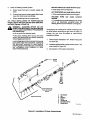
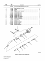
3-2.
MTXC
3501
M
Gun
Installation
TB-135
146
3-4.
MTXC
3501
M
GUN
INSTALLATION
(Figure
3-2)
a
WARNING:
ELECTRIC
SHOCK
can
kill;
ROBOT
ARM
MOVEMENT
can
cause
serious
injury
or
death;
INCORRECT
PROCEDURES
can
cause
Injury.
Do
not
touch
live
electrical
parts.
Shut
down
welding
power
source
and
robot
control,
and
disconnect
input
power
employing
lockout/tagging
procedures.
Lockout/tagging
procedures
consist
of
removing
input
power
plug
from
receptacle,
padlocking
line
disconnect
switch(es)
in
open
position,
removing
fuses
from
fuse
box(es),
or
shutting
off
and
red-tagging
circuit
breaker(s)
or
other
disconnecting
device(s).
MOVING
PARTS
can
cause
serious
Injury.
Keep
away
from
moving
parts.
HOT
SURFACES
can
cause
severe
burns.
Allow
cooling
period
before
touching
gun.
1.
Instafl
and
secure
insulatorto
gun
usingthe
supplied
flat
washers,
lock
washers,
and
socket
head
screws.
2.
Secure
900
mounting
bracket
to
gun
using
supplied
socket
head
screws.
3.
Secure
90
bracket
to
Axis
6
mount
using
supplied
socket
head
screws.
4.
Secure
outlet
cable
to
adapter
by
tightening
nut
from
cable
onto
adapater.
5.
Connect
touch
sensor
leads
from
gun
to
leads
from
outlet
cable.
Connect
leads
from
outlet
cable
to
cord
at
gas/current
sensing
control
or
to
matching
connector
at
robot
manipulator.
Polarity
is
not
important.
3-5.
WATER
CONNECTIONS
(Water-Cooled
Models
Only)
4A
CAUTION:
OVERHEATING
of
Gas
Metal
Arc
Welding
gun
can
damage
gun.
If
using
a
water
cooled
gun
and
recirculating
coolant
system,
make
connections
directly
from
the
coolant
system
to
gun
hoses.
Check
entire
cooling
system
periodically
for
proper
coolant
flow.
A.
Connections
To
Gun
1.
Push
quick-disconnect
fitting
on
water
hose
onto
barbed
titling
at
gun
(see Figure
3-3)
until
locking
ring
snaps
down.
2.
To
release
hose,
push
locking
ring
up
until
disengaged;
pull
hose
from
fitting.
B.
Connections
To
Coolant
Supply
1.
Self-Contained,
Recirculating
Coolant
System
CAUTION:
INCORRECT
COOLANT
will
damage
gun.
Use
only
coolant
specified
in
recirculating
coolant
system
manual.
Do
not
use
tap
water,
automotive
antifreeze,
or
plain
distilled
or
deionized
water.
Use
MILLER
Part
No.
109
973
water
soluble
coolant
or
a
mixture
of
pure
commercial
ethylene
or
propylene
glycol
and/or
water
soluble
lubricants
in
distilled
or
deionized
water.
Failure
to
comply
with
these
instructions
may
void
the
warranty.
a.
Route
hoses
from
gun
to
coolant
system.
b.
Connect
hoses
to
coolant
system
input
and
output
fittings.
The
hoses
have
5/8-18
left-hand
male
fittings.
Insulator
OM-1556
Page
4

2.
Utility
Or
Building
Coolant
System
MOVING
PARTS
can
cause
serious
Injury.
a.
Route
hoses
from
gun
to
coolant
supply
and
drain.
b.
Connect
one
hose
to
coolant
supply.
Both
hoses
have
5/8-18
left-hand
male
fittings.
c.
Route
remaining
hose
to
a
proper
drain.
3-6.
FIELD
INSTALLATION
OF
WATER-COOLED
NOZZLE
ONTO
AIR-COOLED
GUN
(MIX
3502
Mod
els
Only)
(Figures
3-3
And
3-4)
a
WARNING:
ELECTRIC
SHOCK
can
kIll;
ROBOT
ARM
MOVEMENT
can
cause
serious
Injury
or
death;
INCORRECT
PROCEDURES
can
cause
Injury.
Do
not
touch
live
electrical
parts.
Shut
down
welding
power
source
and
robot
control,
and
disconnect
input
power
employing
lockout/tagging
procedures.
Lockout/tagging
procedures
consistof
removing
input
power
plug
from
receptacle,
padlocking
line
disconnect
switch(es)
in
open
position,
removing
fuses
from
fuse
box(es),
or
shutting
off
and
red-tagging
circuit
breaker(s)
or
other
disconnecting
device(s).
Keep
away
from
moving
parts.
HOT
SURFACES
can
cause
severe
burns.
Allow
cooling
period
before
touching
gun.
WELDING
WIRE
can
cause
puncture
wounds.
The
welding
wire
and
all
metalparts
in
contact
with
it
are
electrically
energized
when
the
welding
power
source
contactor
is
energized.
Changing
the
air-cooled
gun
to
a
water-cooled
gun
can
be
done
without
removing
the
gun
from
the
robot.
To
change
the
gun
from
air-cooled
to
water-cooled,
proceed
as
follows:
1.
Remove
parts
indicated
in
3-4.
Retain
these
parts
for
future
use.
2.
Installed
supplied
water-cooled
nozzle
parts
in
the
order
shown
in
Figure
3-3.
3.
See
Section
3-5
for
water
connections.
TB-i
14
230
FIgure
3-3.
installatIon
Of
Water-Cooled
Nozzle
Barbed
FittIng
U8e
Nut8
Retained
From
Air-Cooled
Nozzle
Install
These
Parts
1.
TIp
Adapter
2.
Nut
3.
BushIng
4.
Baffle
5.
Contact
Tip
6.
InsulatIon
Sleeve
7.
Nozzle
Body
OM-1
556
Page
5

SECTION
4-
MAINTENANCE
*
Retain
Nuts
For
Installation
Of
Water-Cooled
Nozzle
18.114
229
4-1.
INSPECTION
AND
UPKEEP
a
WARNING:
ELECTRIC
SHOCK
can
kill;
ROBOT
ARM
MOVEMENT
can
cause
serious
Injury
or
death;
INCORRECT
PROCEDURES
can
cause
Injury.
Do
not
touch
live
electrical
parts.
Shut
down
welding
power
source
and
robot
control,
and
disconnect
input
power
employing
lockouttagging
procedures.
Lockout/tagging
procedures
consist
of
removing
input
power
plug
from
receptacle,
padlocking
line
disconnect
switch(es)
in
open
position,
removing
fuses
from
fuse
box(es),
or
shutting
off
and
red-tagging
circuit
breaker(s)
or
other
disconnecting
device(s).
MOVING
PARTS
can
cause
serIous
Injury.
Keep
away
from
moving
parts.
HOT
SURFACES
can
cause
severe
burns.
Allow
cooling
period
before
touching
gun.
WELDING
WIRE
can
cause
puncture
wounds.
The
welding
wire
and
all
metal
parts
in
contact
with
it
are
electrically
energized
when
the
welding
power
source
contactor
is
energized.
Usage
and
shop
conditions
determine
the
frequency
and
type
of
maintenance
required.
At
minimum,
inspect
welding
gun
and
outlet
cable
monthly
as
follows:
1.
Inspect
gun
and
phenolic
plates
for
broken
areas,
cracks,
and
loose
parts;
tighten,
repair,
and
replace
as
required.
2.
Carefully
remove
weld
spatter
or
dirt
from
around
the
nozzle
opening.
3.
Repair
or
replace
as
required
all
hoses
and
cables;
give
particular
attention
to
frayed
and
cracked
insulation
and
areas
where
cables
enter
equipment.
4.
Remove
grease
and
dirt
from
components,
and
moisture
from
electrical
parts
and
cables.
5.
Clean
outlet
cable
liner
using
compressed
air
whenever
the
wire
is
removed.
a
CAUTION:
FLYING
DIRT
AND
METAL
PARTICLES
can
injure
personnel
and
damage
equIpment.
Point
outlet
cable
liner
only
in
a
safe
direction
away
from
personnel
and
equipment
when
cleaning
with
compressed
air.
Remove
These
Parts
1.
Contact
Tip
*2.
Nuts
3.
lip
Adapter
4.
Bushing
5.
0-RIng
6.
Ceramic
insulator
7.
Nozzle
FIgure
3-4.
Removal
Of
Air-Cooled
Nozzle
OM-1556
Page
6

4-2.
CONTACT
TUBE
REPLACEMENT
4A
WARNING:
ELECTRIC
SHOCK
can
kill;
ROBOT
ARM
MOVEMENT
can
cause
serious
Injury
or
death;
INCORRECT
PROCEDURES
can
cause
Injury.
Do
not
touch
live
electrical
parts.
Shut
down
welding
power
source
and
robot
control,
and
disconnect
input
power
employing
lockout/tagging
procedures.
Lockout/tagging
procedures
consist
of
removing
input
power
plug
from
receptacle,
padlocking
line
disconnect
switch(es)
in
open
position,
removingfusesfrom
fuse
box(es),
or
shutting
off
and
red-tagging
circuit
breaker(s)
or
other
disconnecting
device(s).
MOVING
PARTS
can
cause
serious
injury.
Keep
away
from
moving
parts.
HOT
SURFACES
can
cause
severe
burns.
Allow
cooling
period
before
touching
gun.
WELDING
WIRE
can
cause
puncture
wounds.
The
welding
wire
and
all
metal
parts
in
contact
with
it
are
electrically
energized
when
the
welding
power
source
contactor
is
energized.
1.
Remove
nozzle.
2.
Cut
off
any
portion
of
welding
wire
which
extends
beyond
end
of
contact
tube.
Manually
retract
welding
wire.
3.
Remove
contact
tube.
4.
Install
new
contact
tube
and
reinstall
nozzle.
5.
6.
5.
Manually
thread
welding
wire
out
of
new
contact
tube.
4-3.
CHANGING
WIRE
SIZE
When
changing
wire
size,
it
is
necessary
to
change
the
contact
tube
and
wire
drive
rolls,
and
may
be
necessary
to
change
the
outlet
cable.
Obtain
parts
for
wire
size
desired,
and
proceed
as
follows:
WARNING:
ELECTRIC
SHOCK
can
kIll;
ROBOT
ARM
MOVEMENT
can
cause
serious
Injury
or
death;
INCORRECT
PROCEDURES
can
cause
injury.
Do
not
touch
live
electrical
parts.
Shut
down
welding
power
source
and
robot
control,
and
disconnect
input
power
employing
lockout/tagging
procedures.
Lockout/tagging
procedures
consist
of
removing
input
power
plug
from
receptacle,
padlocking
line
disconnect
switch(es)
in
open
position,
removingfusesfrom
fuse
box(es),
or
shutting
off
and
red-tagging
circuit
breaker(s)
or
other
disconnecting
device(s).
MOVING
PARTS
can
cause
serious
Injury.
Keep
away
from
moving
parts.
HOT
SURFACES
can
cause
severe
burns.
Allow
cooling
period
before
touching
gun.
WELDING
WIRE
can
cause
puncture
wounds.
The
welding
wire
and
all
metalparts
in
contact
with
it
are
electrically
energized
when
the
welding
power
source
contactor
is
energized.
1.
Cut
off
welding
wire
at
contact
tube,
and
retract
from
gun.
2.
Disconnect
touch
sensor
leads,
and
remove
outlet
cable
from
gun.
3.
Disconnect
touch
sensor
leads,
and
remove
outlet
cable
from
wire
drive
assembly.
4.
Prepare
and
install
new
outlet
cable
as
instructed
in
Section
3-2.
Slide
liner
from
outlet
cable
into
gun.
Secure
outlet
cable
to
adapter
by
tightening
nut
from
cable
onto
adapter.
7.
Connect
touch
sensor
leads.
Polarity
is
not
important.
8.
Remove
nozzle
and
contact
tube
from
gun.
9.
Install
new
contact
tube,
and
reinstall
nozzle
onto
gun.
10.
Thread
welding
wire.
OM-1556
Page
7

SECTION
5-
PARTS
LIST
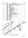
Figure
5-1.
MTX
3502
AIr
Cooled
Gun
B114
229
1
11
1~
5
6
7
8
9
11
14
OM-1556
Page
8

Description
Quantity
113
883
FIgure
5-1.
MTX
3502
AIr
Cooled
gun
PACKING
SWITCH
COVER
SHIM
0-RING
(S-32)
BOOT,
rbbr
ADAPTER,
tip
INSULATION,
bush
0-RING
(P12)
INSULATOR,
cer
NOZZLE
(No.
8)
NOZZLE
(No.
7
short)
NOZZLE
(No.
8
long)
NOZZLE(No.10)
NOZZLE
(No.
6
short)
NOZZLE
(No.
6
long)
NOZZLE
(No.
7
long)
NOZZLE
(fine)
CONTACT
TIP
(Q0.9)
CONTACT
TIP
(Q0.8)
CONTACT
TIP
(01.2)
CONTACT
TIP
(01.6)
CONTACT
TIP,
.023
wire..
NUT
1
6
1
1
6
1
1
1
1
1
1
1
1
1
1
1
1
1
1
1
1
1
1
1
1
1
1
1
2
1
1
Optional
Equipment
Item
No.
Part
No.
SCREW,
cap
-
hex
hd
8MM
x
1.25
x
15MM
SCREW,
cap
-
skt
hd
M5
x
.8
x
14mm
0-RING
(S-25)
ADAPTER,
brs
SCREW,
cap
-
skt
hd
4MM
x
.7
x
12MM
MICROS
WITCH
2
3
4
5
6
7
8
9
10
11
12
13
14
15
16
16
16
16
16
16
16
16
17
17
17
17
17
18
19
115
527
115
526
108
780
114
249
115
524
108
772
108
773
108
774
108
775
108
779
108
766
108
768
108
776
108
778
108
777
108
784
.110
854
.108
793
.108
785
.112
471
.112
470
.112
469
.112
468
108
789
.108
788
.108
786
.108
790
.129
886
108
767
114
251
108
770
POWER
SUPPLY
WIRE,
(consisting
of)
PROTECTION
TUBE
OM-1556
Page
9

Description
Quantity
132
296
FIgure
5-2.
MTXC-3501M
Air
Cooled
Gun
133
992
135
496
133
995
133
994
1
2
1
1
1
1
1
1
1
1
1
1
1
1
1
1
1
1
1
Optionai
Equipment
OM-1556
Page
10
FIgure
5-2.
MTXC-3501
M
AIr
Cooled
Gun
Item
No.
Part
No.
WIRE
ASSEMBLY,
pwr
supply........
0-RING
HOOD
NOZZLE
HOLDER
ASSEMBLY
133996
TIPBODY
2
3
4
5
6
6
6
6
6
6
7
8
9
10
10
10
10
11
108
789
.108
788
108
792
108
786
.113
954
.108
790
133
997
108
778
108
777
108
784
.110
854
108
793
108
785
133
993
CONTACT
TIP,
(00.8)
CONTACT
TIP,
(00.8)
CONTACT
TIP,
(01.0)
CONTACT
TIP,
(01.2)
CONTACT
TIP,
.045
wire
CONTACT
TIP,
(01.6)
INSULATION
BUSHING
0-RING,
(P12)
INSULATOR,
cer
NOZZLE,
(No
8)
NOZZLE,
(No
7
short)
NOZZLE,
(No
8
long)
NOZZLE,
(No
10)
NOZZLE
ASSEMBLY
..-
2
4
>
.....
2
I
I
I
11
I
I
S.
6
7
SB-125
145

Item
No.
Part
No.
Description
113
882
FIgure
5-3.
MTXW
5001
Water
Cooled
Gun
115
569
CONVERSION
KIT,
air
to
water
cooled
nozzle
(consisting
of)
114250
~ADAPTER,tip
Quantity
1
2
3
4
5
6
6
6
7
8
9
10
11
12
13
14
15
16
17
18
19
20
21
22
23
24
25
26
114
255
114
252
114
253
129886
113
954
113
955
114
251
108
770
114
254
114526
114
257
113
950
082
368
010
607
056851
115527
115
526
108
780
114
249
115
524
108
772
108
773
108
774
108
775
108
779
108
766
108
767
120
975
NUT
INSULATION,
bush
BAFFLE
CONTACT
TIP,
.023
wire
CONTACT
TIP,
.045
wire
CONTACT
TIP,
.062
wire
POWER
SUPPLY
CABLE,
(consisting
of)
PROTECTION
TUBE
INSULATION
SLEEVE
NOZZLE,
water
cooled
FITTING,
water
WATER
HOSE,
(consisting
of)
CLAMP,
hose
FITTING,
hose-brs
nut
5/8-18
LH
.
FITTING,
hose-brs
barbed
nipple
3/16
TBG
SCREW,
cap
-
hex
hd
8MM
x
1.25
x
15MM
SCREW,
cap
-
skt
hd
M5
x
.8
x
14mm
0-RING
(S-25)
ADAPTER,
brs
SCREW,
cap
-
skt
hd
4MM
x
.7
x
12MM
MICROSWITCH
PACKING
SWITCH
COVER
SHIM
0-RING
(S-32)
BOOT,
rbr
NUT
TIP
GAUGE
1
1
1
1
1
1
1
1
1
1
1
1
2
2
1
1
1
1
6
1
1
6
1
1
1
1
I
1
2
1
1
25
.23
FIgure
5-3.
MTXW
5001
Water
Cooled
Gun
B.114
230
OM-1556
Page
11


-
 1
1
-
 2
2
-
 3
3
-
 4
4
-
 5
5
-
 6
6
-
 7
7
-
 8
8
-
 9
9
-
 10
10
-
 11
11
-
 12
12
-
 13
13
-
 14
14
-
 15
15
-
 16
16
-
 17
17
-
 18
18
-
 19
19
-
 20
20


Miller JK000000 Owner's manual
- Category
- Welding System
- Type
- Owner's manual
- This manual is also suitable for
Ask a question and I''ll find the answer in the document
Finding information in a document is now easier with AI
Related papers
-
Miller MTX 3502 ROBOT GUN Owner's manual
-
Miller JG073823 Owner's manual
-
-
-
-
-
-
Miller KA25 Owner's manual
-
-
Other documents
-
Hasbro Titanium War Within Fallen Operating instructions
-
Kawasaki F series Installation And Connection Manual
-
 Hontech HT-C02 User manual
-
 PHI VILLA HD-S7-432 Operating instructions
-
 PHI VILLA THD9-305-042 Operating instructions
-
 PHI VILLA THD7-0604-102 Operating instructions
-
 AirZone North America TT-3502 User manual
-
Becker ADF3500 User manual
-
YASKAWA Motoman DX200 Instructions Manual
-
 PHI VILLA THD7-201-097 Operating instructions


