Page is loading ...

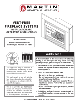
This is an unvented gas-red heater.
It uses air (oxygen) from the room
in which it is installed. Provisions for
adequate combustion and ventilation air
must be provided. See page 9.
READ AND SAVE THESE INSTRUCTIONS
WARNINGS
If the information in this manual is not followed
exactly, a fire or explosion may result causing
property damage, personal injury or loss of life.
– Donotstoreorusegasolineorotherammable
vapors and liquids in the vicinity of this or any
other appliance.
– WHAT TO DO IF YOU SMELL GAS
• Do not try to light any appliance.
• Do not touch any electrical switch; do not use
anyphoneinyourbuilding.
• Immediately call your gas supplier from a
neighbor's phone. Follow the gas supplier's
instructions.
• If you cannot reach your gas supplier, call the
redepartment.
– Installation and service must be performed by
a qualiedinstaller, service agency or the gas
supplier.
MODEL: 33ISDG
Natural Gas or Propane/LPG
Control Type: Milli-Volt and T-Stat
VENT-FREE
FIREPLACE SYSTEMS
INSTALLATION AND
OPERATING INSTRUCTIONS
WARNINGS
This appliance may be installed in
an aftermarket, permanently located,
manufactured (mobile) home, where
not prohibited by local codes.
This applicance is for use only with the
type of gas indicated on the rating plate.
This applicance is not convertible for
use with other gases.

2 23D8036
CONTENTS
Important Safety Information ..................................3
Product Features ......................................................5
Operation ..............................................................5
Natural Gas ..........................................................6
Propane/LPG ........................................................6
Specications ...........................................................6
Ignition Controls ....................................................6
Pilot .......................................................................6
Thermal Generator ...................................................6
Getting Started ..........................................................7
General Installation Information .............................8
Removing Screen .................................................8
Installing Canopy ..................................................8
Codes ...................................................................9
Adequate combustion and Ventilation Air .............9
Clearances and Height Requirements ..................11
Fireplace Framing...................................................14
Securing Heater to Floor ........................................15
Connecting the Gas ................................................16
Checking Gas Pressure .........................................18
Electrical Wiring (Milli-Volt) ...................................19
Electrical Wiring (Fan) ............................................21
Log Placement ........................................................22
Flame Appearance ..................................................26
Checking the Burner Flame ...................................27
Operating Instructions ...........................................28
What to Do if You Smell Gas ..............................28
Milli-Volt Control Lighting Instructions .................29
Match Lighting Instructions .................................30
Cleaning and Servicing ..........................................31
Troubleshooting .....................................................32
Illustrated Parts Breakdown ..................................34
Fireplace Assembly ...........................................34
Grate and Base Assembly .................................36
Logs....................................................................38
Warranty ..................................................Back Cover

23D8036 3
9. The installation must conform with local codes or, in the
absence of local codes, with the National Fuel Gas Code,
ANSI Z223.l/NFPA54.
10. This unit complies with ANSI Z21.11. Unvented Heat-
ers.
11. Do not install the heaters in a bathroom or bedroom.
12.Correctinstallationoftheceramicberlogs,properloca-
tionoftheheater,andannualcleaningarenecessaryto
avoidpotentialproblemswithsooting.Sooting,resulting
from improper installation or operation, can settle on sur-
facesoutsidethereplace.Seelogplacementinstructions
for proper installation.
13.Avoidanydraftsthatalterburneramepatterns.Donot
allowfanstoblowdirectlyintoreplace.Donotplace
ablowerinsideburnareaofrebox.Ceilingfansmay
createdraftsthatalterburneramepatterns.Sootingand
improperburningwilloccur.
14. Caution: Candles, incense, oil lamps, etc. produce com-
bustionbyproductsincludingsoot.Vent-freeappliances
willnotlterorcleansootproducedbythesetypesof
products. In addition, the smoke and/or aromatics (scents)
may be reburnt in the vent-free appliance which can
produce odors. It is recommended to minimize the use
of candles, incense, etc. while the vent-free appliance is
in operation.
15.Thisisanunventedgas-redheater.Itusesair(oxygen)
from the room in which it is installed. Provisions for
adequate combustion and ventilation air must be provided.
Seepage9.
INSTALLER
Please leave these instructions with the appliance.
OWNER
Please retain these instructions for future reference
.
IMPORTANT
Read these instructions carefully before installing or trying to operate this vent-free gas heater.
IMPORTANT SAFETY INFORMATION
8. CARBON MONOXIDE POISONING:Earlysignsof
carbon monoxide poisoning are similar to the u with
headaches, dizziness and/or nausea. If you have these
signs,obtainfreshairimmediately.Havetheheaterser-
vicedasitmaynotbeoperatingproperly.
Continued on page 4
•Anychangetothisheateroritscontrolscanbedangerous.
•Improperinstallationoruseoftheheatercancauseseriousinjuryordeathfromre,
burns,explosionorcarbonmonoxidepoisoning.
•Donotallowfanstoblowdirectlyintothereplace.Avoiddraftsthatalterburnerame
patterns.
•Donotuseablowerinsert,heatexchangerinsertorotheraccessory,notapprovedfor
usewiththisheaterwhereapplicable.
WARNING
1. Dueto high temperatures,the applianceshould
belocatedoutoftrafcandawayfromfurnitureand
draperies.
2. Children and adults should be alerted to the hazard
ofhighsurfacetemperatureandshouldstayawayto
avoidburnsorclothingignition.
3. Young children should be carefully supervised
whentheyareinthesameroomwiththeappliance.
4. Donotplaceclothingorotherammablematerial
on or near the appliance.
5. Anysafetyscreenorguardremovedforservicing
anappliance,mustbereplacedpriortooperatingthe
heater.
6. Installationandrepairshouldbedonebyaquali-
edserviceperson.
7. To prevent malfunction and/or sooting, an
unventedgasheatershouldbecleanedbeforeuseand
atleastannuallybyaprofessionalserviceperson.More
frequentcleaningmayberequiredduetoexcessivelint
fromcarpeting,beddingmaterials,etc.Itisimperative
thatcontrolcompartments,burnersandcirculatingair
passagewaysbekeptclean.

4 23D8036
IMPORTANT SAFETY INFORMATION
Continued from page 3
16. Keep room area clear and free from combustible materials,
gasolineandotherammablevaporsandliquids.
17.Unventedgasheatersareasupplementalzoneheater.They
arenotintendedtobetheprimaryheatingappliance.
18.Unventedgasheatersemitmoistureintothelivingarea.
Inmosthomesofaverageconstruction,thisdoesnotpose
a problem. In houses of extremely tight construction,
additional mechanical ventilation is recommended.
19.Duringmanufacturing,fabricatingandshipping,various
components of this appliance are treated with certain oils,
lmsorbondingagents.Thesechemicalsarenotharmful
butmayproduceannoyingsmokeandsmellsastheyare
burnedoffduringtheinitialoperationoftheappliance;
possiblycausingheadachesoreyeorlungirritation.This
isanormalandtemporaryoccurrence.
The initial break-in operation should last two to three
hours with the burner at the highest setting. Provide
maximumventilationbyopening windows ordoorsto
allowodorstodissipate.Anyodorsremainingafterthis
initialbreak-inperiodwillbeslightandwilldisappear
with continued use.
20.Input ratings are shown in BTU per hour and are for
elevations up to 2,000 feet. For elevations above 2,000
feet,inputratingsshouldbereduced4percentforeach
1,000 feet above sea level. Refer to the National Fuel Gas
Code.
21.Theapplianceanditsappliancemaingasvalvemustbe
disconnectedfromthegassupplypipingsystemduring
any pressure testing of that system at test pressures in
excessof1/2psig(3.5kPa).
22.Theappliancemustbeisolatedfromthegassupplypiping
systembyclosingitsequipmentshutoffvalveduringany
pressuretestingofthegassupplypipingsystemattest
pressuresequaltoorlessthan1/2psig(3.5kPa).
23.Donotusethisroomheaterifanyparthasbeenunder
water.Immediatelycallaqualiedservicetechnicianto
inspect the room heater and to replace any part of the
controlsystemandanygascontrolwhichhasbeenunder
water.
24.Neverburn solid fuels in areplace where a unvented
room heater is installed.
27.InstallationofthisventedgaslogintheCommonwealth
of Massachusetts requires the damper be permanently
removed or welded in the full open position. In addition, a
naturallyventedgaslogmaynotbeinstalledinabedroom
orbathroomintheCommonwealthofMassachusetts.Flex
lineinstallationmustnotexceed36".
We suggest that our gas hearth
products be installed and
serviced by professionals who
are certied in the U.S.by the
National Fireplace Institute
®
(NFI) as Gas Specialists.
Never connect unit to private (non-
utility) gas wells. This gas is commonly
known as wellhead gas.
WARNING
25.Alwayshaveareplacescreeninplacewhentheappliance
is in operation and, unless other provisions for combustion
airareprovided,thescreenmusthaveanopening(s)for
induction of combustion air.
26.FORMASSACHUSETTSRESIDENTSONLY:
This product must be installed by a
licensed plumber or gas tter when
installed within the Commonwealth of
Massachusetts.
WARNING
28.Anyoutsideairductsand/orashdumpsinthereplace
shallbepermanentlyclosedattimeofapplianceinstal-
lation.
Failure to keep the primary air openings
of the burners clean may result in
sooting and property damage.
WARNING

23D8036 5
Yourvent-freereplacemustbemountedtotheoororthereplacehearth.
OPERATION
Thisunventedgasheaterrequiresnooutsideventingandburnscleanlywithhighheatingefciency.
Piezo Ignitor
Fireplace
Screen
Control Knobs
PRODUCT FEATURES
Optional
Face Plate
Figure 1 - Unvented Gas Heater with Control Access Door Open
On/Off Switch
Blower
Optional T-stat
Sensor

6 23D8036
NATURAL GAS
Milli-Volt and T-Stat Pressure
RegulatorPressureSetting:3.5"w.c.
PilotRegulator:3.5"w.c.
GasInletPressure:Max.101/2"w.c.
Min.5"w.c.
PRODUCT FEATURES and SPECIFICATIONS
PROPANE/LPG
Note: An external regulator is required to reduce supply pressure to a maximum of 13" w.c.
Milli-Volt and T-Stat Pressure
RegulatorPressureSetting:10"w.c.
GasInletPressure:Max.13"w.c.
Min.11"w.c.
IGNITION CONTROLS
Piezoignitorallowsignitionofthepilotwithouttheuseofmatchesorbatteries.
Milli-Volt and T-Stat control has four (4) positions:
OFF - Allgastothegaslogsisshutoffatthevalve.
IGN - Valvepositiontolight/maintainastandingpilot.
ON - ValvepositiontoturnON/OFFlogsetwithremoteswitch/thermostat.
LOW/HI - Variablepositiontocontrolameheight(heatoutput).Bothfrontandrearburnersareinoperationto
providerealisticglowandyellowame.
PILOT
Thegaslogheateristtedwithaspeciallydesignedsafetypilotlight(ODSassembly)whichsensestheamountofoxygen
availableintheroomandshutsthegaslogheateroffiftheoxygenlevelbeginstodropbelowasatisfactorylevel.Thepilot
canonlyberelitwhenadequatefreshairisavailable.
THERMAL GENERATOR
Themilli-voltgaslogpilotisttedwithamilli-voltgeneratortoprovidepowerforremoteactivation.
Gas Rate
Model Number Control Max BTU/HR Min BTU/HR
33ISDNTG Millivolt 28,000 19,000
33ISDNVG T-Stat 28,000 19,000
Gas Rate
Model Number Control Max BTU/HR Min BTU/HR
33ISDPTG Millivolt 28,000 23,000
33ISDPVG T-Stat 28,000 23,000

23D8036 7
GETTING STARTED
MAKE SURE YOU HAVE RECEIVED ALL PARTS
Checkyourpackinglisttoverifythatalllistedpartshavebeenreceived.Youshouldhavethefollowing:
•Installation/Operatinginstructions • BlackLouvers(5)
•33"unventedgasheaterwithbrickpanels. • Canopy
•Volcanicrockandrockwool • Two(2)anchoringscrews
•Mountingscrewsforcanopy
•Logbox(refertoinstallationinstructions)
Accessoryfaceplatesavailabletonishtheinsert.
•DIFACESM Blacksmallface33"Hx43"W • DIFACELG Blacklargeface36"Hx50"W
Accessoriesincludebrasstrimandmountinghardware
Themilli-voltcontrolledversionofthisheateristheonlystyledesignedtobeoperatedwithoptionaldevicesforON/OFF
functions.Thefollowingoptionsmaybeusedwiththemilli-voltcontrolledheater.Theseoptionsarenotpackagedwiththe
logset.
•HandheldRemotewithReceiver • Wallswitchwith15'wire. • WallT-statwith15'wire.
• Hand held Thermostat Remote with Receiver • Thermostat Sensor
•Handlethegaslogburnerassemblybythegrateonly.Donotpicktheunitupbythe
burners.
•Glovesarerecommendedwhenhandlingceramicberlogstopreventskinirritation
fromloosebers.Logsarefragile—handlewithcare.
WARNING
Carefullyinspectthecontentsforshippingdamage.Ifanypartsaremissingordamaged,immediatelyinformthedealer
fromwhomyoupurchasedtheappliance.Do not attempt to install any part of the appliance unless you have all parts
in good condition.
WHAT YOU WILL NEED FOR INSTALLATION
Youmusthavethefollowingitemsavailablebeforeproceedingwithinstallation…
•Externalregulator(forpropane/L.P.G.and1/2lb.NaturalGasSystemsonly)
•Pipingwhichcomplieswithlocalcodes • Sedimenttrap
• Tee joint • Pipe wrench or appropriate size crescent wrench set
•Phillipsheadscrewdriver • Drillwith5/32"bit
•Optionalfaceplatekit. • Manualshutoffvalve
•OptionaltrimkitforinstallationintowallorfreestandingMantlewithoutthreepiecefaceplate
•Pipesealantapprovedforusewithpropane/LP.G(Resistanttosulfurcompounds)

8 23D8036
REMOVING SCREEN
Removereplacescreenbypushingscreenframepanelup
and out. See Figure 2.
Figure 2 - Removing Fireplace Screen
GENERAL INSTALLATION INFORMATION
INSTALLING CANOPY
1. Removethereplacescreenasdescribedintheprevioussection.
2. Aligncanopywiththeholesinthetopframeassembly.See Figure 3.
3. Install the ve (5) screws (in owner’s manual packaging) which attach the canopy to the top frame assembly. See
Figure 3.
4. Tightenallscrews.Makesurethecanopyislevelandsecure.Installthereplacescreen.
Figure 3 - Installing Canopy
Do not operate the unit without the
screen frame panel and canopy
installed.
WARNING
NOTE: Fireplace screen must
be removed to access log box
and to install canopy.

23D8036 9
GENERAL INSTALLATION INFORMATION
CODES
Adheretoalllocalcodesor,intheirabsence,thelatesteditionofTHENATIONALFUELGASCODEANSIZ223.1or
NFPA54whichcanbeobtainedfrom…
American National Standards Institute, Inc.
1430Broadway
New York, NY 10018
or
National Fire Protection Association, Inc.
BatterymarchPark
Quincy,MA02269
ADEQUATE COMBUSTION AND VENTILATION AIR
Thisheatershallnotbeinstalledinaconnedspaceorunusuallytightconstruction unless provisions are providedfor
adequate combustion and ventilation air.
The National Fuel Gas Code, (ANSI Z223.1/NFPA54),denesaconnedspaceasaspacewhosevolumeislessthan50
cubicfeetper1,000BTUperhour(4.8m
3
perkw)oftheaggregateinputratingofallappliancesinstalledinthatspaceand
anunconnedspaceasaspacewhosevolumeisnotlessthan50cubicfeetper1,000BTUperhour(4.8m
3
per kw) of the
aggregateinputratingofallappliancesinstalledinthatspace.Roomscommunicatingdirectlywiththespaceinwhichthe
appliancesareinstalled,throughopeningsnotfurnishedwithdoors,areconsideredapartoftheunconnedspace.
UNUSUALLY TIGHT CONSTRUCTION IS DEFINED AS CONSTRUCTION WHERE…
a) wallsandceilingsexposedtotheoutsideatmospherehaveacontinuouswatervaporretarderwitharatingof1perm
(6x10
11
kgperpa-sec-m
2
)orlesswithopeningsgasketedorsealed;and
b) weatherstripinghasbeenaddedonopenablewindowsanddoors,and
c) caulkingorsealantsareappliedtoareassuchasjointsaroundwindowanddoorframes,betweensoleplatesandoors,
betweenwall-ceilingjoints,betweenwallpanels,atpenetrationsforplumbing,electrical,andgaslines,andatother
openings.
Do not install the heater …
•Wherecurtains,furniture,clothing,orotherammableobjectsarelessthan42"from
the front of the heater.
•Inhightrafcareas.
• In windy or drafty areas.
WARNING

10 23D8036
W
H
BTU/Hr =
BTU/Hr =
WARNING
The following formula can be used to determine the maximum heater rating per the denition of unconned
space:
(L1 + L2) Ft x (W) Ft x (H) Ft
50
Consider two connecting rooms with an open area between, with the following dimensions:
L1 = 15
1
/2 Ft., L2 = 12 Ft., W = 12 Ft., H = 8 Ft.
(15
1
/2 + 12) x (12) x (8)
50
If there were a door between the two rooms the calculation would be based only on the room with the heater.
(15
1
/2) x (12) x (8)
50
GENERAL INSTALLATION INFORMATION
Figure 4 - Example of a Large Room with 1/2 Wall Divider
Counter
Fireplace
x 1000
x 1000 = 52800 BTU/Hr
x 1000 = 29760 BTU/Hr
If the area in which the heater may be operated is smaller than that dened as an
unconnedspaceorifthebuildingisofunusuallytightconstruction,provideadequate
combustionandventilationairbyoneofthemethodsdescribedintheNationalFuel
GasCode,ANSIZ223.1/NFPA54,Section5.3orapplicablelocalcodes.
WARNING
BTU/Hr =

23D8036 11
33"
15
1
/
4
"
22
3
/
4
"
23
7
/
8
"
B
A
9"
Minimum
9"
Minimum
42"
Minimum
CLEARANCES and HEIGHT REQUIREMENTS
NOTE: Clearances are necessary to combustible
surfaces only. No clearance is necessary for
noncombustible surface.
Sidewall clearances: The clearance from the inside of
theappliancetoanycombustibleadjacentwallshouldno
belessthan9."See Figure 5.
Ceiling clearance: Theceilingmustbeatleast42"from
thetopofthereboxopening.See Figure 5.
Back wall clearance: Theappliancecanbeplacedagainst
the combustible back wall.
Floor clearance: Thereplacemaynotbeinstalledonto
anycombustibleooringmaterial,suchascarpeting,vinylor
tilewithoutthehearthoraminimum22GA(0.030")metal
oraminimum1/2"woodenbasecoveringtheentirewidth
and depth of the base.
Mantel clearances: Thecanopysuppliedwiththeunit
must be installed. If a combustible mantel is installed. It must
meet the clearance requirements shown in Figure 8.
ThedimensionsshowninFigures5and8anddenedinthereplacemanufacturer's
instructions are minimum clearances to maintain when installing this heater. Left and
right clearances are determined when facing the front of the heater.
Follow these instructions carefully to ensure safe installation. Failure to follow
instructions exactly can create a re hazard.
WARNING
Figure 5 - Sidewall and Ceiling Minimum
Clearances
Figure 6 - Dimensions for Installing in
Masonry Fireplace or a UL Listed Box
BEFORE INSTALLING THE FIREPLACE INSERT
Havereplaceoorandchimneyprofessionallycleanedto
remove ashes, soot, creosote or other obstructions. Close
andsealanyfreshairventsorashclean-outdoorslocatedon
oororwall
Accessory Face Plates
A B
Small 33" 43"
Large 36" 50"

12 23D8036
10"
1
2"
14"
26"
8"
12"
10"
8"
6"
2
1
/2"
Hood
No combustible materials
within 8” of opening.
Do not cover louvers.
No combustible materials
within 8" of opening.
Do not cover louvers.
Hood
8"
4"
2
1
/2"
10"
6"
8"
HEAT RESISTANT MATERIAL (MINIMUM REQUIRE-
MENTS) WITH NO WOODEN MANTEL OR OTHER COM-
BUSTIBLE PROJECTION
Heat resistant material (minimum requirements) with wooden mantel
orothercombustibleprojection:
To install the heater with a wooden mantel shelf or other combustible
projectionabove,rstmeasuretheheatresistantmaterialshownin
Figure 7.
CLEARANCES and HEIGHT REQUIREMENTS
Example: Amantelmay
project from the wall
a maximum of 2
1
/2" at
minimum of 8" above
theopening,andamaxi-
mum of 12" at a mini-
mum of 26" above the
opening.
Figure 7 - Measuring Heat Resistant
Material for Mantel
Figure 8 - Minimum Mantel Clearance
Figure 9 isanexampleofanunsafemantelinstallation.Themantel
projects 4" at 8" above the opening, exceeding the maximum
acceptable distance of 2
1
/2".Themantelalsoprojects8"at10"
abovetheopening,exceedingthemaximumacceptabledistance
of6".
Ifyourmantelproleisunsafe,youmayeither:
• Raisethemanteltoanacceptableheightor,
• Remove the mantel.
Figure 9 - Unsafe Mantel Clearance

23D8036 13
Combustible
Material
Non-combustible
Material
5"
1”
CLEARANCES and HEIGHT REQUIREMENTS
Thegaslogheatermustbeinstalledatleast5"aboveanycombustibleooringmaterial,suchascarpetingortile,whichis
closerthan14"tothebaseofthereplace.See Figure 10.
Figure 10 - Minimum Clearance above Combustible Flooring

14 23D8036
22
5
/8"
33
1
/2"
16"
33
1
/2"
16"
33
1
/2"
27
1
/2"
22
5
/8"
31
7
/8"
REF
16"
37
1
/4"
45
3
/4"
15
3
/8" 33
1
/2"
64
1
/4"
FIREPLACE FRAMING
Ifunitistobe“builtin,”replaceframingcanbebuilt
before or after the appliance is set in place. BE SURE
THAT ALL PACKING MATERIAL HAS BEEN
REMOVED FROM THE UNDERSIDE OF THE
UNIT PRIOR TO SETTING THE FIREBOX IN
PLACE. ConstructreplaceframingfollowingFigures
11 through 14. See Figure 6 on page 11 forreplace
dimensions.Theframingheadersmaynotrestdirectly
ontopoftherebox.
Thereplacemaybeinstalleddirectlyonacombustible
oororaraisedplatformofanappropriateheight.Do
notplacereplaceoncarpeting,vinyl,tileorothersoft
oorcoverings.Itmay,however,beplacedonatwood,
plywood,particleboardorotherhardsurfaces.Besure
replacerestsonasolidcontinuousoororplatform
withappropriateframingforsupportandsothatnocold
aircanenterfromundertherebox.
Figure 12 - Inner Wall Installation
Figure 14 - Corner Installation
Figure 13 - Stud Location
Figure 11 - Outer Wall Installation
Header

23D8036 15
NOTE: Clearance requirements as detailed
in “Clearances and Height Requirements”
section of this manual must be met before
securing heater in place.
To prevent movement, the heater must be secured
totheoororhearth.
1. Liftofflouversandremovethescreen.
2. Removelogset.
3. Toremovethegrateandbaseassembly,takeout
two screws as shown in Figure 15.
4. Liftgrateandbaseassemblyoutoftherebox.
5. Securethe rebox withtwo anchoringscrews
(
3
/16"x1
1
/4"length)suppliedwiththereplace
system.See Figure 16 .
Note: If the unit is mounted on carpeting,
tile or combustible material without the
hearth, a metal or wooden base covering
the entire width and depth of the base
must be installed.
SECURING HEATER TO FLOOR
Figure 15 - Removing Grate and Base Assembly
Figure 16 - Securing Firebox to Floor or Hearth

16 23D8036
NOTICE: Aqualiedgasapplianceinstallermustconnecttheheatertothegassupply.Consultall
local codes.
IMPORTANT: Loosen the pipe adapter on the ex tube before installing to the system piping.
Figure 17 - Gas Connection
To Heater
Valve
Stainless
Flexible Tube
CONNECTING THE GAS
Usenewblackorsteelpipe.Internallytinnedcopperorcoppertubingcanbeused
perNationalFuelCode,section2.6.3,providinggasmeetshydrogensuldelimits,
andwherepermittedbylocalcodes.Gaspipingsystemmustbesizedtoprovide
minimum inlet pressure (listed on Data Plate) at the
maximumowrate(BTU/Hr).Undue
pressure loss will occur if the pipe is too small.
A manual shutoff valve must be installed upstream of the appliance. Union tee
and plugged
1
/8"NPTpressuretappingpointshouldbeinstalledupstreamofthe
appliance. See Figure 17.
CAUTION
Manual Shutoff
Valve
Pipe
Pipe Coupling
Always use an external regulator for all propane/L.P.G. heaters and high pressure one to two-pound systems only, to
reducethesupplytankpressuretoamaximumof13"w.c.Thisisinadditiontotheinternalregulatorintheheatervalve.
CHECK GAS TYPE: Thegassupplymustbethesameasstatedontheheater'srating
plate. If the gas supply is different, DO NOT INSTALL THE HEATER. Contact your
dealer for the correct mode.
WARNING
Locations that Pressure
Tapping Point May Be
Installed
Gas Supply
Inlet

23D8036 17
Toreachfactoryinstalledexline,gothroughaccessdooronrightorleftsideofrebox.
CONNECTING THE GAS
CHECKGASTYPE:Thegassupplymustbethesameasstatedonheater'sratingplate.
Locatedbehindthecontrolaccessdoor (Figure 1, page 5). If the gas supply is different,
DO NOT INSTALL the heater. Contact your dealer for the correct model. Connecting to
the wrong gas type may result in property damage or personal injury.
CAUTION
Connecting directly to an unregulated
propane/L.P.G. tank can cause an
explosion.
WARNING
Figure 18 - Access Holes
Cord Protector
Manual Gas Shutoff
(Recommended Outlet
Positioned Vertical)
Stainless Flex Line
Access Door
for Gas Line

18 23D8036
CHECKING GAS PRESSURE
Testallgasjointsfromthegasmetertotheheatervalveforleaksusingagasanalyzerorsoapandwatersolutionaftercom-
pletingconnection.DO NOT USE AN OPEN FLAME.
CheckthegaspressurewiththeapplianceburningandthecontrolsettoHIGH.
Opencontrolaccessdooroneithersideofunittondvalveandregulatorreferredtobelow.See Figure 17, page 16.
MILLIVOLT CONTROL (Figure 19)
Thevalveregulatorcontrolstheburnerpressurewhich
should be checked at the pressure test point.
Turn captured screw counter clockwise two or three
turnsandthenplacetubingtopressuregaugeovertest
point (Use test point “OUT” closest to control knob).
Aftertakingpressurereading,besureandturncaptured
screwclockwisermlytore-seal.Donotovertorque.
Checkforgasleaks.
Figure 19 - Pressure Test Point Location
Milli-Volt Control
Test Port “OUT”
Connecting directly to an
unregulated propane/LPG tank
can cause an explosion.
WARNING
Thestainlessexlineisontherightsidefacingthereplaceandcan
connect to either a
3
/8 NPT female or
1
/2 NPT male pipe. To connect from
the opposite side, route the pipe under the rear portion of the unit.

23D8036 19
ELECTRICAL WIRING (MILLI-VOLT)
Themilli-voltvalveisaself-poweredcombinationgascontrol
THAT DOES NOT REQUIRE 110 VAC TO OPERATE.
Figure 20 - Wiring Diagram
Optional Wall
Switch or Remote
Receiver
Switch
On/Off
Switch
On/Off
Switch
Wall
Switch
ODS
Pilot
Millivolt
Valve
TH = 3
TP = 1
TP/TH = 2
ODS
Pilot
Spade
Terminal
Labelallwirespriortodisconnection
when servicing controls. Wiring
errors can cause improper and
dangerous operation. Verify proper
operation after servicing.
WARNING
CONNECTING OPTIONAL WALL SWITCH OR THERMOSTAT
1. Use18awg,two-wirecable,15feetmaximumlength.
2. At one end of the cable, connect both wires to the wall switch or thermostat. At the other end, connect one wire to TP/TH
andonewiretoTH,orconnectthewallswitch/thermostattothetwomale(0.25")terminalsontheleftsideoftheunit.
The color of the wires does not matter.
See Figure 20 and installation instructions
provided with optional wall switch, thermo-
statorremotecontrolforwiringinstructions.
Amaximumlengthof15feetof18awgtwo
conductor wire is to be used for wall switch
or thermostat installations.
Note thermostats and switches must
be suitable for milli-volt operation.

20 23D8036
ELECTRICAL WIRING (MILLI-VOLT)
A. COMPLETE MILLIVOLT SYSTEM CHECK
(“A”Reading-ThermostatcontactsCLOSED-ControlKnob“ON”-MainburnershouldturnON)
a. Ifthereadingismorethan100milli-voltsandtheautomaticvalvestilldoesnotcomeon,replacethecontrol.
b. Iftheclosedcircuitreading(“A”reading)islessthan100millivolts,determinecauseforlowreading,proceedto
SectionBbelow.
B. Thermopile Output Reading Check
(“B”Reading-ThermostatcontactsOPEN-MainburnerOFF)
1. Checkgaspressuretotheunit.Ifgaspressureiswithinminimumandmaximumondataplate,thencheckpilot
voltage,325millivoltsminimum.Iftheminimummilli-voltreadingisnotobtainable,replacepilot.
CONNECT
METER SWITCH OR METER
CHECK TO LEADS TO THERMOSTAT READING
TEST TEST TERMINALS CONTACTS SHOULD BE
A COMPLETE 2 & 3 CLOSED CLOSED
SYSTEM
B THERMOPILE 1 & 2 OPEN OPEN
OUTPUT
CHECKING SYSTEM OPERATION
Themilli-voltsystemandindividualcom-
ponentsmaybecheckedwithamilli-volt
meterhavinga0-1000mVrange.Conduct
eachcheckshowninchartbelowbycon-
nection meter test leads to terminals as
indicated.
CONNECTING REMOTE RECEIVER (Figure 21)
THESE InSTRUCTIOnS SUPERCEdE THE SECTIOn
EnTITLEd “HEaRTH MOUnT” In THE MILLI-VOLT
Hand-HELd REMOTE InSTRUCTIOnS SUPPLIEd
WITH THE REMOTE.
1. Removecoveroncontrolpaneltoshowopeningforremote
receiver.
2. Connect the remote connectors located in the unit.
3. Slideremotereceiverintheopeningofcontrolpanel.Use
two screws provided to attach remote receiver to the control
panel.
4. Replace Cover.
NOTE: Do not place remote in combustion chamber.
Figure 21 - Installing Remote Receiver
Remote
Receiver
Cover
/