
E
User Manual
Benützersanleitung
Guida Utente
Manual de uso
Manuel de l’utilisateur
TYPE NR. BDH5011
Philips
Business
Solutions
G
I
S
F
E

TABLE OF CONTENTS
1. Important Safety Instructions . . . . . . . . . . . . . . . . . . . . . . . . . . . . . . . . . . . . . . . . .3
2. FCC Statement . . . . . . . . . . . . . . . . . . . . . . . . . . . . . . . . . . . . . . . . . . . . . . . . . . .5
3. Cleaning and Maintenance . . . . . . . . . . . . . . . . . . . . . . . . . . . . . . . . . . . . . . . . . .6
4. Product Features . . . . . . . . . . . . . . . . . . . . . . . . . . . . . . . . . . . . . . . . . . . . . . . . . .8
5. Package Contents . . . . . . . . . . . . . . . . . . . . . . . . . . . . . . . . . . . . . . . . . . . . . . . .10
6. Understanding your Display . . . . . . . . . . . . . . . . . . . . . . . . . . . . . . . . . . . . . . . . .12
6.1 Front View . . . . . . . . . . . . . . . . . . . . . . . . . . . . . . . . . . . . . . . . . . . . . . . . . .12
6.2 Rear View . . . . . . . . . . . . . . . . . . . . . . . . . . . . . . . . . . . . . . . . . . . . . . . . . .12
6.3 Remote Control . . . . . . . . . . . . . . . . . . . . . . . . . . . . . . . . . . . . . . . . . . . . .13
7. Connecting the Display . . . . . . . . . . . . . . . . . . . . . . . . . . . . . . . . . . . . . . . . . . . .15
7.1 Connecting a DVD Player . . . . . . . . . . . . . . . . . . . . . . . . . . . . . . . . . . . . . .15
7.2 Connecting a HDTV Decoder Set-Top Box . . . . . . . . . . . . . . . . . . . . . . . . .16
7.3 Connecting a VCR . . . . . . . . . . . . . . . . . . . . . . . . . . . . . . . . . . . . . . . . . . . .16
7.4 External Audio Connections . . . . . . . . . . . . . . . . . . . . . . . . . . . . . . . . . . . .17
7.5 Connecting a PC Using RGB or DVI Video Input . . . . . . . . . . . . . . . . . . . . .18
7.6 RS-232 Remote Control Connections . . . . . . . . . . . . . . . . . . . . . . . . . . . . .19
8. Using your Display - Basics . . . . . . . . . . . . . . . . . . . . . . . . . . . . . . . . . . . . . . . . .22
8.1 Powering ON / OFF . . . . . . . . . . . . . . . . . . . . . . . . . . . . . . . . . . . . . . . . . .22
8.2 Selecting Signal Source . . . . . . . . . . . . . . . . . . . . . . . . . . . . . . . . . . . . . . . . .23
8.3 Adjusting Sound Volume . . . . . . . . . . . . . . . . . . . . . . . . . . . . . . . . . . . . . . . .24
9. Using with HDTV . . . . . . . . . . . . . . . . . . . . . . . . . . . . . . . . . . . . . . . . . . . . . . . .25
9.1 Understanding HDTV . . . . . . . . . . . . . . . . . . . . . . . . . . . . . . . . . . . . . . . . .25
10. Advanced Functions . . . . . . . . . . . . . . . . . . . . . . . . . . . . . . . . . . . . . . . . . . . . . . .27
10.1 Picture-In-Picture (PIP) / Side-by-Side Picture (POP) . . . . . . . . . . . . . . . . . .27
10.2 Widescreen (16:9 Aspect Ratio) Viewing Modes . . . . . . . . . . . . . . . . . . . . .31
10.3 On-Screen Display (OSD) Settings . . . . . . . . . . . . . . . . . . . . . . . . . . . . . . .33
10.4 Sleep Timer Settings . . . . . . . . . . . . . . . . . . . . . . . . . . . . . . . . . . . . . . . . . .34
10.5 Variable and Fixed Audio Output . . . . . . . . . . . . . . . . . . . . . . . . . . . . . . . . .35
10.6 Sound Adjustments . . . . . . . . . . . . . . . . . . . . . . . . . . . . . . . . . . . . . . . . . . .35
10.7 Inner speaker ON/OFF . . . . . . . . . . . . . . . . . . . . . . . . . . . . . . . . . . . . . . . .36
10.8 Signal Frequency Information Display . . . . . . . . . . . . . . . . . . . . . . . . . . . . . .37
11. Picture Adjustment . . . . . . . . . . . . . . . . . . . . . . . . . . . . . . . . . . . . . . . . . . . . . . .39
11.1 For AV/Component Video (480i signal) . . . . . . . . . . . . . . . . . . . . . . . . . . . .39
11.2 For Component Video (480p, 720p and 1080i signal) . . . . . . . . . . . . . . . . . .41
11.2 For Component Video (480p, 720p and 1080i signal) - Contd. . . . . . . . . . . .43
11.3 For RGB / DVI . . . . . . . . . . . . . . . . . . . . . . . . . . . . . . . . . . . . . . . . . . . . . . .44
12. Troubleshooting . . . . . . . . . . . . . . . . . . . . . . . . . . . . . . . . . . . . . . . . . . . . . . . . . .46
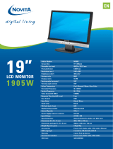
13. Specifications . . . . . . . . . . . . . . . . . . . . . . . . . . . . . . . . . . . . . . . . . . . . . . . . . . .47
14. Wall Mount (Option) . . . . . . . . . . . . . . . . . . . . . . . . . . . . . . . . . . . . . . . . . . . . . .55
15. Limited Warranty . . . . . . . . . . . . . . . . . . . . . . . . . . . . . . . . . . . . . . . . . . . . . . . . .56
2
User Manual BDH5011

3
User Manual BDH5011
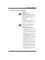
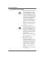
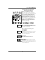
1. IMPORTANT SAFETY INSTRUCTIONS
WARNING
RISK OF ELECTRIC SHOCK
DO NOT OPEN
The lightning flash with arrow-head symbol
within a triangle is intended to alert the user to
the presence of uninsulated dangerous voltage
within the product enclosure that may be of
sufficient magnitude to constitute a risk of
electric shocks to persons.
WARNING
To reduce the risk of electric shock, do not
remove the front or back covers.
No user-serviceable parts inside. Refer servicing
to qualified service personnel only.
The exclamation point within a triangle
is intended to tell the user that important
operating and servicing instructions are
explained.
WARNINGS & PRECAUTIONS
• To prevent damage which may result in fire
or shock hazard, do not expose this product
to rain or moisture.
• To prevent electric shock, do not remove
cover. No user serviceable parts are inside.
Refer servicing to qualified service personnel
only.
• Keep display away from excessive dust, high
temperatures, moisture or direct sunlight.
• Use in a well-ventilated area and do not
cover ventilation openings.
• Unauthorized modification of this equipment
or using an unshielded connecting cable may
cause excessive interference.
• When the display is not in use for a long
period of time, disconnect it from the
electric outlet.
• If the picture displayed is in any way
abnormal, turn off the unit and disconnect it
from the electric outlet.Verify your signal
wire connections and reconnect the display
to the electric outlet.
• Disconnect from the electric outlet before
cleaning. Do not use liquid or aerosol
cleaners. Use only a slightly damp cloth for
cleaning.
• Do not place this product on an unstable
cart, stand or table.The product may fall,
causing serious damage.

• Do not place the unit on a bed, sofa, rug, or
other similar surface. Never place the unit
near or over a radiator or heat source.
• Do not install unit in an enclosed area unless
proper ventilation is provided.
• The unit should be operated from the type
of power source indicated on the label. If the
type of available power is unknown, consult
your dealer or local power company.
• The unit is equipped with a 3-pin grounded
plug.The plug will only fit into a grounded
power outlet.This is a safety feature. If you
are unable to insert the plug into the outlet,
contact your electrician. Do not alter the
plug; this will defeat the safety feature.
• Do not rest objects on the power cable and
avoid placing power cable near high traffic
areas.
• Do not overload wall outlets and extension
cables as this can result in a risk of fire or
electric shock.
• Disconnect the unit from the mains supply
and refer servicing to qualified service
personnel under the following conditions:
• Power cable or plug is damaged or frayed.
• Liquid has been spilled into the product.
• Unit has been exposed to water or
moisture.
• Unit does not operate normally when the
operating instructions are followed.Adjust
only those controls that are covered by
the operating instructions, improper
adjustment of other controls may result in
damage which often requires extensive
work by a qualified technician to restore
the unit to normal operation.
• Unit has been dropped or the cabinet has
been damaged.
• Unit exhibits a distinct change in
performance, indicating a need for service.
4
User Manual BDH5011

5
User Manual BDH5011
2. FCC STATEMENT
FCC Compliance Statement
The equipment has been tested and found to
comply with the limits for a Class B digital
device, pursuant to part 15 of FCC rules.
These limits are designed to provide reasonable
protection against harmful interference when the
equipment is operated in a commercial
environment.
This equipment generates, uses, and can radiate
radio frequency energy and, if not installed and
used in strict accordance with the instruction
manual, may cause harmful interference to radio
communications.
There is no guarantee that interference will not
occur in a particular installation. If this
equipment does cause harmful interference to
radio or television reception, which can be
determined by turning the equipment off and on,
the user is encouraged to try to decrease the
interference by one or more of the following
measures:
• Reorient or relocate the receiving antenna.
• Increase the distance between the equipment
and the receiver.
• Connect the equipment into an outlet on a
circuit different from that to which the
receiver is connected.
• Consult the dealer or an experienced
radio/TV technician for help.
Operation of this equipment in a residential area
is likely to cause harmful interference in which
case the user will be required to decrease the
interference at the owner’s expense.
Shielded interconnected cables and shielded
power cords must be used with this equipment
to ensure compliance with the pertinent RF
emission limits governing this device.
Changes or modifications not expressly
approved by the manufacturer could void the
user's authority to operate the equipment and
void the warranty.
Canadian Compliance Statement
This Class B digital apparatus meets all
requirements of the Canadian Interference
Causing Equipment Regulations.
Cet appareil numérique de la Classe B respecte
toutes les exigences du Règlement sur le
matériel brouilleur du Canada.

6
User Manual BDH5011
3. CLEANING AND MAINTENANCE
Cautions When Using the Plasma Display
• Do not bring your hands, face or objects
close to the ventilation holes of the plasma
display.Top of plasma display is usually very
hot due to the high temperature of exhaust
air being released through the ventilation
holes. Burns or personal injuries may occur if
any body parts are brought too close. Placing
any object near the top of the display could
also result in heat related damages to the
object as well as to the display itself.
• Be sure to disconnect all cables before
moving the plasma display. Moving the display
with its cables attached may damage the
cables, and thus, cause fire or electric shock
danger.
• Disconnect the power plug from the wall
outlet as a safety precaution before carrying
out any type of cleaning or maintenance
procedure.
Front Panel Cleaning Instructions
• The front of the display has been specially
treated.Wipe the surface gently using only a
cleaning cloth or a soft, lint-free cloth.
• If the surface is particularly dirty, soak a soft,
lint-free cloth in a mild detergent solution.
Wring the cloth to remove excessive liquid.
Wipe the surface of the display to remove
dirt.Then use a dry cloth of the same type
to dry the surface.
• Do not scratch or hit the surface of the
panel with fingers or hard objects of any
kind.
• Do not use volatile substances such as insect
sprays, solvents and thinners.
Cabinet Cleaning Instructions
• If the cabinet becomes dirty, wipe the
cabinet with a soft, dry cloth.
• If the cabinet is extremely dirty, soak a lint-
free cloth in a mild detergent solution.Wring
the cloth to remove as much moisture as
possible.Wipe the cabinet.Then use a dry
cloth of the same type to dry the surface.
• Do not allow any water or detergent to
come into contact with the surface of the
display.
If water or moisture gets inside the unit,
operating problems and electrical hazards
may occur.
• Do not scratch or hit the cabinet with hard
objects of any kind.

• Do not use volatile substances such as insect
sprays, solvents and thinners on the cabinet.
• Do not place anything made from rubber or
PVC near the cabinet for extended periods
of time.
Avoid Still Images
• Do not allow a still picture to be displayed
for extended periods of time.This can cause
a permanent image to remain on the plasma
display. Examples of still images may include:
still computer images, still video game
images, still logos or pictures, text and
images displayed in 4:3 Normal mode.
Contents of this manual is subject to
change without notice.
Trademark Credits
• VGA is a trademark of IBM Corporation.
• Macintosh is a registered trademark of Apple
Computer Corporation.
• SVGA is a registered trademark of the Video
Electronics Standard Association.
• All other trademarks are the properties of
their respective owners.
7
User Manual BDH5011

8
User Manual BDH5011
4. PRODUCT FEATURES
• Advanced Digital Image Processing
Advanced digital processor with adaptive
motion de-interlacing converts all 15KHz
signals into progressive scan for a brighter,
flicker free image.
• Pull-Down for Film Scan Conversion
Built-in 3:2 pull-down processing can
automatically detect and convert film
content to properly display with minimal
motion artifacts.
• 3D Comb Filter
Built-in 3D comb filter converts analog signal
into a digital signal for more accurate
processing, eliminating cross-color
interference for superior NTSC video
performance.
• Dual HD Component Video Inputs
Two high-definition component video inputs
with auto-detection capabilities will
automatically synchronize the display to
match the incoming signal source without
manual intervention.
• Picture-in-Picture (PIP)
Watch two programs simultaneously using
the display’s picture-in-picture with four
selectable window position settings.
• Side-by-Side Picture (POP)
Watch two programs simultaneously by
splitting the screen in half.
• HDTV Signal Compatible
This display is capable of accepting 1080i and
720p HDTV signals via an external HDTV
decoder with RGB or Component Video
outputs.
• Digital Zoom Modes
Digital zoom modes gets rid of black bars
common to non-16:9 aspect ratio movie
content.

• DVI Digital Video Interface with HDCP
(High-Bandwidth Digital Content
Protection Protocol) Standard DVI interface
supports the lastest in digital video
peripherals equipped with DVI HDCP digital
video output(s).This means that digital
content can now be passed from sources
such as a digital DVD player, directly to this
display without digital-to-analog conversion
that causes loss of video quality. Direct
digital-to-digital connection ensures the
absolute best in video quality.
• 280x1024 SXGA Support
The onboard digital scaling engine can accept
various PC and HDTV signals and digitally
map the signals to fit within 1366 x 768
pixels.
• Discrete Power ON/OFF
Separate Power ON/OFF buttons on the
remote control facilitates the recording of IR
macros with advanced system setups.
• Direct Input Selection Buttons
Separate input selection keys on the remote
control allow quick and easy selection of
various inputs.
• RS-232 Serial Connection
The RS-232 command set includes front
panel lock, input selection, power on/off,
volume and other standard RS-232 command
controls.
9
User Manual BDH5011

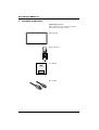
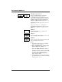
5. PACKAGE CONTENTS
Supplied Accessories
Please verify that you received the following
items with your package content:
Plasma Display
Remote Control
User Manual
Power Cable
10
User Manual BDH5011

VGA Cable
Batteries
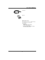
Optional Accessories
The following accessories are available and may
be purchased from your local sales
representative:
• Wall Mount
• Composite Video Cable (RCA)
• S-Video Cable (Mini-Din)
• Component Video Cable (RCA to RCA)
• Audio Cable (RCA Cable)
11
User Manual BDH5011

12
User Manual BDH5011
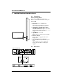
6. UNDERSTANDING YOUR DISPLAY
6.1 Front View
Power (Standby) Button
Turns power on/off from standby mode.
There is a 3-second wait between on/off cycles.
Status LED:
• Not Illuminated - No AC Power
detected
If the main power switch (rear of panel) is
turned off, this LED will not illuminate.
• Solid Yellow - Standby (Power OFF)
with AC power detected
The LED will illuminate in yellow color if the
display is shut-off but the main power cord is
plugged into the back of the unit.
• Solid Green - Power ON
• Input Button
Use this button to switch between available
inputs.
• Menu +/- Buttons
Use this menu to engage the On Screen
Display menu.
• Volume Adjustment +/- Buttons
Use these buttons to adjust volume up and
down.
These buttons also serve as adjustment
buttons when the On Screen Display is
engaged.
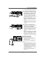
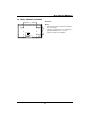
6.2 Rear View
RGB OUTRGB IN RS-232DVI IN
VIDEO CONNECTORS
RGB OUTRGB IN RS-232DVI IN
RGB / COMPUTER RELATED CONNECTORS

13
User Manual BDH5011
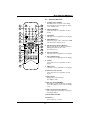
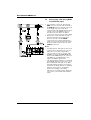
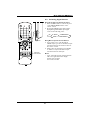
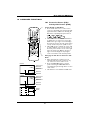
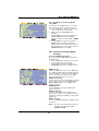
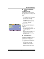
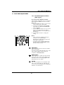
6.3 Remote Control
1. Standby Power On/Off
Push this button to switch on the display
from Standby mode. Push it again to switch
off to Standby mode.
2. Number Keypad
These buttons are not applicable for this
display.
3. QuickView
This button is not applicable for this display.
4. PIP/POP Source
Changes the input source of the PIP or POP
sub-window. (See Chapter 10.1)
5. PIP (Picture-in-Picture Button)
Turns on PIP (Picture-in-Picture) mode and
POP (Side-by-Side) picture mode.
(See chapter 10.1).
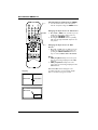
6. Favorite Channel
This button is not applicable for this display.
7. Closed Captioning|
This button is not applicable for this display.
8. V-Chip
These buttons are not applicable for this
display.
9. MTS Stereo
This button is not applicable for this display.
10. Channel Lock / Fav. Set
These buttons are not applicable for this
display.
11. Sleep Timer
Engages Sleep Timer Settings.
(See Chapter 10.4).
12. Discrete Power ON/OFF
Press OFF to switch the display to Standby
mode. Press ON to power on from standby
mode.
13. Direct Input Selection Buttons
Direct input signal selection by pressing the
appropriate button.
14. Sound Mute On/Off
15. Volume +/-
Turns volume up or down.
2
1
3
5
6
7
4
8
9
10
12
13
23
22
11
21
20
19
18
17
16
15
14

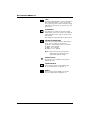
14
User Manual BDH5011
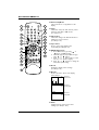
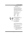
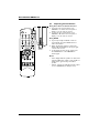
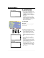
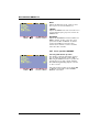
16. Channel Up/Down
These buttons are not applicable to this
display.
17. Swap
This button swaps the main and sub picture
windows under PIP or POP modes.
(See chapter 10.)
18. PIP Position
This button changes the PIP sub-window to
4 different corner locations.
(See Chapter 10.)
19. Input Select
Press to select input signal modes
sequentially. (See Chapter 8.2.)
20. MENU Adjustment
1. Show OSD menu by pressing or
button or MENU button.
2. Scroll through the major OSD category
using or button.
3. Press or button again to select
sub-options within the category.
4. Press or buttons to change the
actual sub-option setting.
21. Recall
Recalls the default picture settings.
(See Chapter 11.)
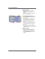
22. Display
Press to show the status of the display.
23. Wide
Toggles between various aspect ratio
settings. (See Chapter 10.2.)
PIP
AV1
AV2
COMPONENT 1
1080I
RGB
M:06
AV Mode (PIP/POP On)
Component Mode
RGB Mode
Main Source
PIP/POP Source
Main Source
Incoming Signal
Main Source
Display Mode
2
1
3
5
6
7
4
8
9
10
12
13
23
22
11
21
20
19
18
17
16
15
14

7. CONNECTING THE DISPLAY
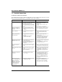
7.1 Connecting a DVD Player
Using Component Video Input
1. Connect the green-colored (labeled as Y)
jack from the DVD to the green-colored
Y1-jack of the display.
2. Connect the red-colored (labeled as PR or
CR) jack from the DVD to the red-colored
PR1/CR1 jack of the display.
3. Connect the blue-colored (labeled as PB or
CB) jack from the DVD to the blue-colored
PB1/CB1 jack of the display.
4. Connect the red (R) and white (L) audio
jacks from the DVD to the R and L audio-in
jacks located next to the PR1/CR1 connec-
tor.
Note:
There are two sets of component inputs
provided.You can use either set of
component inputs to connect your DVD.
Using S-Video Input
1. Connect the S-Video (4-pin DIN) connector
from the DVD to the S-VIDEO input on
the back of display.
2. Connect the red (R) and white (L) audio
jacks from the DVD to the R and L audio-in
jacks located next to the S-VIDEO connec-
tor.
Using Composite (AV) Video Input
1. Connect the yellow (video) connector from
the DVD to the yellow VIDEO 1 input on
the back of display.
2. Connect the red (R) and white (L) audio
jacks from the DVD to the R and L audio-in
jacks located next to the yellow VIDEO 1
connector.
15
User Manual BDH5011

7.2 Connecting a HDTV
Decoder Set-Top Box
Using Component Video Input
1. Connect the green (labeled as Y) jack from
the HDTV Set-top box to the green Y1 jack
of the display.
2. Connect the red (labeled as PR or CR) jack
from the HDTV Set-top box to the red
PR1/CR1 jack of the display.
3. Connect the blue (labeled as PB or CB)
jack from the HDTV Set-top box to the blue
PB1/CB jack of the display.
4. Connect the red (R) and white (L) audio
jacks from the HDTV Set-top box to the R
and L audio-in jacks located next to the
PR1/CR connector.
Using RGB Input
1. Connect the 15-pin D-Sub RGB connector
from the back of the HDTV Set-top box to
the RGB-IN connector located on the back
of the display.
2. Connect the red (R) and white (L) audio-out
jacks from the HDTV Set-top box to the R
and L audio-in jacks located to the left of the
S-VIDEO connector.
7.3 Connecting a VCR
Using S-Video Input
1. Connect the S-Video (4-pin DIN) connector
from the VCR to the S-VIDEO input on the
back of display.
2. Connect the red (R) and white (L) audio
jacks from the VCR to the R and L audio-in
jacks located next to the S-VIDEO
connector.
Using Composite Input
1. Connect the yellow (video) out connector
from the VCR to the yellow Video 1 input on
the back of the display.
2. Connect the red (R) and white (L) audio-out
jacks from the VCR to the R and L audio-in
jacks located next to the yellow Video
connector.
16
User Manual BDH5011

17
User Manual BDH5011
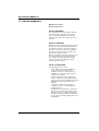
7.4 External Audio Connections
Connecting External Amplified Speakers
1. This display can be connected to an external
set of amplified speakers using the AUDIO
OUT jacks located on the back of the
display. In addition, this display is equipped
with a small 3.5 mm phono style plug for
remote turn-on applications that will auto-
matically send a remote turn-on/off signal to
the external amplified speakers.
2. Connect the red (R) and white (L) AUDIO
OUT jacks at the right hand side of the
connector panel to the external amplified
speaker.
3. As an option, you may use the remote turn-
on plug. Please note that not all external
amplified speakers can accept remote-turn
on signals.
Connecting to an External Amplifier
1. This display can be connected to an external
amplifier using the AUDIO OUT jacks
located on the back of the display. In
addition, this display is equipped with a small
3.5 mm phono style plug for remote turn-on
applications that will automatically send a
remote turn-on/off signal to the external
amplifier.
2. Connect the red (R) and white (L) AUDIO
OUT jacks from right side of the connector
panel to the external amplifier or receiver.
3. As an option, you may use the remote turn-
on plug. Please note that not all external
amplifiers can accept remote-turn on signals.
Using the Subwoofer Out
(Connecting a Subwoofer)
1. This display is equipped with a subwoofer
output for connecting to an external
amplified subwoofer.
2. Connect the subwoofer output jack to the
external subwoofer using an RCA cable.
Notes:
• The AUDIO OUT RCA jacks can be set to
either Fixed or Variable audio output levels.
(See Chapter 10.5 for more information).
• The RCA subwoofer outputs frequencies
below 120Hz.The subwoofer will use the
same Fixed or Variable audio output setting
as AUDIO OUT RCA jacks.
• The 3.5mm phono/earphone output level is
always used for remote turn on/off
applications.

7.5 Connecting a PC Using RGB
or DVI Video Input
1. For most PC’s, connect the 15-pin D-Sub
RGB connector from the back of the PC to
the RGB-IN connector located on the back
of the display. If you have a PC that is
equipped with a DVI (Digital Visual Interface),
you may connect the PC DVI connector
from the back of the PC to the DVI-In
connector located on the back of the display.
2. Connect the red (R) and white (L) audio
jacks from the PC to the R and L jacks
located to the left of the S-VIDEO
connector. If you are using a DVI interface,
simply connect the (R) and (L) audio jacks to
the R and L jacks located to the left of the
VIDEO 1 connector.
Notes:
• Your PC may have audio jacks in the form of
a 3.5mm phono plug. If this is the case, you
will need to use a phono-plug to RCA
converter cable in order to connect audio.
• A RGB loop-out labeled iaRGB OutlB will
allow another RGB display to be connected.
The RGB loop-out will display the same
signal as the RGB In signal source.
• The physical display resolution is a maximum
of 1024x768 dots when aspect ratio is set to
4:3 and 1366x768 dots when set to 16:9.
If the PC’s display resolution exceeds these
maximums, the display will have to artificially
eliminate dots in order to fit within the
physical dot capability of the display.
Therefore, it is possible that the display may
not be able to show details with adequate
clarity.
18
User Manual BDH5011

19
User Manual BDH5011
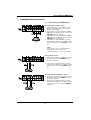
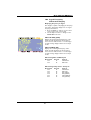
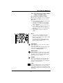
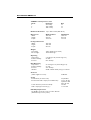
7.6 RS-232 Remote Control
Connections
RS-232 Serial Terminal Overview
This display is equipped with an RS-232 serial
terminal for using the display with computer
controls.The RS-232 serial terminal conforms to
the RS-232C interface specification.The
computer will require a software application
(such as programming language software) which
allows the computer to send and receive control
data that can support the communications
parameters listed below.
Communications Parameters
These parameters are required to setup
communications with the display.
Specification: RS-232C
Sync Method: Synchronous
Baud Rate: 9600 bps
Parity: None
Character: Length 8 Bits
Stop Bit: 1 Bits
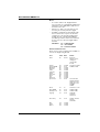
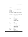
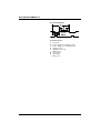
Pin Layout for RS-232 Terminal
The RS-232C terminal pin layout is as follows:
Pin 1: Received Line Signal Detector (Data
Carrier Detect)
Pin 2: Received Data (RXD)
Pin 3: Transmit Data (TXD)
Pin 4: Data Terminal Ready (DTR)
Pin 5: Signal Ground
Pin 6: Data Set Ready (DSR)
Pin 7: Request To Send (RTS)
Pin 8: Clear To Send (CTS)
Pin 9: Ring Indicator
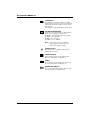
Basic Format for Command Parameters
In order to transmit data from the computer to
the display, the data must be sent in 1-byte-hex
format.
The command code (see table below) must first
be sent to the display, followed by the desired
value setting in hexadecimal format.
The following is an example of a sequence to
change the displays input to RGB:
Step 1: Send 1-byte for command 91 (input
select) to the display in hex format 0x91
Step 2: Send 1-byte for the value of the RGB
input. In this example, send 0x06.
Step 3: The display will respond back to
the PC with a 1-byte value to confirm
the setting.
RS-232
1
5
9
6

Notes:
• To connect a PC to the display’s RS-232
port, you must use a straight-through RS-232
cable where pins 2 (RX) and 3 (TX) are not
reversed at one end.
• If there is no data to be sent, then it is not
necessary to send the parameter signal.
• If multiple commands are transmitted, make
sure to wait for the response for the first
command to come from the display before
sending the next command. Normally the
sent data byte will be returned as an answer.
In case of an error the next signals will be
returned:
RESPONSE: 70h = MODE ERROR
71h = TEM ERROR
72h = FORMAT ERROR
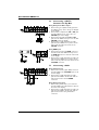
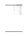
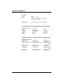
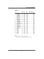
Command Parameters
These remote control commands are available to
send to the display using RS-232.
Item Cmd Data Details
Read 80 81-A7 Reads the
displays current
settings for
command 81
thru A7
Volume 81 01-64H
Set between 01-64H
Power On/Off 83 00-01 00=Off, 01=On
Brightness 85 01-64H
Contrast 86 01-64H
V-Size 87 01-64H
V-Position 88 01-64H
H-Size 89 01-64H
H-Position 8A 01-64H
Color 8E 01-64H
Tint 8F 01-64H
Sharpness 90 01-64H
Input Select 91 00-07
00=TV, 01=AV1,
02=AV2, 03=AV3,
04=Component 1
05=Component 2
06=RGB,
07=DVI
Recall 92 00 00=Initiate a recall
Mute On/Off 95 00-01 00=Off 01=On
PanelKey Lock 96 00-01 00=Off 01=On
Language 97 00-02 00=English,
01=French,
02=Spanish
Color Temp 98 00-03 00=High, 01=Mid,
02=Low,
03=6500D
Bass 9A 01-64H
Treble 9B 01-64H
Balance 9C 01-64H
20
User Manual BDH5011
Page is loading ...
Page is loading ...
Page is loading ...
Page is loading ...
Page is loading ...
Page is loading ...
Page is loading ...
Page is loading ...
Page is loading ...
Page is loading ...
Page is loading ...
Page is loading ...
Page is loading ...
Page is loading ...
Page is loading ...
Page is loading ...
Page is loading ...
Page is loading ...
Page is loading ...
Page is loading ...
Page is loading ...
Page is loading ...
Page is loading ...
Page is loading ...
Page is loading ...
Page is loading ...
Page is loading ...
Page is loading ...
Page is loading ...
Page is loading ...
Page is loading ...
Page is loading ...
Page is loading ...
Page is loading ...
Page is loading ...
Page is loading ...
Page is loading ...
Page is loading ...
Page is loading ...
-
 1
1
-
 2
2
-
 3
3
-
 4
4
-
 5
5
-
 6
6
-
 7
7
-
 8
8
-
 9
9
-
 10
10
-
 11
11
-
 12
12
-
 13
13
-
 14
14
-
 15
15
-
 16
16
-
 17
17
-
 18
18
-
 19
19
-
 20
20
-
 21
21
-
 22
22
-
 23
23
-
 24
24
-
 25
25
-
 26
26
-
 27
27
-
 28
28
-
 29
29
-
 30
30
-
 31
31
-
 32
32
-
 33
33
-
 34
34
-
 35
35
-
 36
36
-
 37
37
-
 38
38
-
 39
39
-
 40
40
-
 41
41
-
 42
42
-
 43
43
-
 44
44
-
 45
45
-
 46
46
-
 47
47
-
 48
48
-
 49
49
-
 50
50
-
 51
51
-
 52
52
-
 53
53
-
 54
54
-
 55
55
-
 56
56
-
 57
57
-
 58
58
-
 59
59


Ask a question and I''ll find the answer in the document
Finding information in a document is now easier with AI
Related papers
Other documents
-
 Novita N10002 Datasheet
-
Gateway Flat Panel Television User manual
-
-
Gateway 50-inch User manual
-
Maxent MX-50X2 Owner's manual
-
-
-
-
LG L2320A Owner's manual
-
