Desa CD32M User manual

Category
Fireplaces
Type
User manual
Save for future reference.
For more information, visit www.desatech.com
WIRELESS HAND-HELD REMOTE CONTROL MODELS HRC100,
HRC101, HRC200 AND HRC201 OPERATING INSTRUCTIONS
For Use With DESA Heating Products Remote Ready Log Sets
and Fireplace Systems
INSTALLING REMOTE RECEIVER
1. Disconnect switch wires from the control valve.
Some units will have an ON/OFF switch with
switch plate that is connected to the control
valve. Other units will have a jumper wire that
will need to be removed from the control valve
(see Figure 1).
2. Remove screws and switch plate as shown in
Figure 1. Discard after removing.
3. Install remote receiver unit onto gas log heater
base using clips (2) and insulating washers
provided.
4. Pushclipsrmlyintoplace(seeFigure2).
5. Connect wires as shown in Figure 3.
Note: On yellow ame models,reuseprovided
phillips head screws and reinstall heat shield over
receiving unit.
INSTALLING WIRELESS REMOTE
CONTROL ACCESSORY
Two 9-volt alkaline batteries (not included) are
required to operate this wireless hand held remote
controlset.Onebatterymustbeinstalledinthe
receiver and one in the hand-held remote control
unit. Note:Onlyusealkalinebatteries.
Installing 9-Volt Battery (Not Included) in
Receiver
1. Locatethebatteryclipmountedontheback
of the receiver.
2. Slidea9-voltbatterythroughtheclip.
3. Attachtheterminalwirestothebattery.
Figure 1 - Disconnecting Wires from
Control Valve
Front
Back
Wires to
Control Valve
Screw
Jumper Wire
Control Valve
Figure 2 - Installing Remote Receiver
Front
Back
Insulating
Washers
Remote
Receiver
Mounting
Clips
Figure 3 - Connecting Wires
Valve
Red Wire
From
Receiver
White
Wire From
Receiver
Battery Clip
ON/OFF Switch with
Switch Plate
www.desatech.com
116710-01C2
9-Volt Battery
Battery
Housing
Installing 9-Volt Battery (Not Included) in
Hand-Held Remote Control Unit
1. Remove battery cover on back of remote
control unit.
2. Removeanddiscardsensortaginsidebattery
housing.
3. Attach terminal wires to the battery. Place
batteryintothebatteryhousing.
4. Replace battery coveronto remote control
unit.
Figure 4 - Installing Battery in Hand-Held
Remote Control Unit
Battery
Cover
Terminal
Wires
Remote Control Unit
REMOTE OPERATION
NOTICE: You must light the pi-
lot before using the hand-held
remote control unit. See Light-
ing Instructions in your owner’s
manual.
1. Afterlighting,letpilotameburnforabout
one minute. Turn control knob to ON posi-
tion.Adjustameadjustmentknobanywhere
between HI and LO. Slide the selector switch
to the REMOTE position (see Figure 5).
Note: The burner may light if hand-held
remote was on when selector switch was last
turned off. You can now turn the burner on and
off with the hand-held remote control unit.
IMPORTANT: Do not leave the selector switch
in the REMOTE or ON position when the pilot
isnotlit.Thiswilldrainthebattery.
Figure 5 - Setting the Selector Switch,
Control Knob and Flame Adjustment
Knob (Available on Some Models) for
Hand-Held Remote Operation
O
F
F
P
I
L
O
T
L
O
I
H
REMOTE
OFF
ON
O
N
Flame Adjustment Knob
(Available on Some Models)
Control Knob
Selector Switch in
REMOTE Position
(Optional Hand-Held
Remote Control)
ON/OFF Series
(Models HRC100 and HRC101)
Hold the control button on the hand-held remote
until burner turns on. Hold the control button again
until burner turns off (see Figure 6).
To Lock press both buttons on hand-held remote
control until light stops flashing. Hand-held
remotecontrolisnowlocked.Ifthereisonit
willbe turned off automatically. In the locked
state,thelightwillnotlightupwhenanybutton
is pressed.
To Unlock press both buttons together on hand-
heldremotecontroluntilthelightstopsashing.
The hand-held remote is now unlocked.
Figure 6 - ON/OFF Hand-Held Remote
Control Unit
Control
Button
Indicator Light
Sensor
Tag
www.desatech.com
116710-01C 3
THERMOSTAT SERIES
(MODELS HRC200 AND HRC201)
The hand-held remote can be operated using
either the manual mode (MANU) or thermostatic
mode (AUTO) (see Figure 7). To select Fahren-
heit/Centigrademodedisplay,carefullypressthe
˚C/˚Fmodebuttonwiththeendofapaperclipor
similar blunt object.
Manual Mode
1. Press the POWER and LOCK buttons together
to turn on the hand-held remote control.
2. PresstheMANUbuttontoturnonthere-
place.
3. Press the POWER and LOCK buttons together
toturnoffthereplace.
Auto (Thermostatic) Mode
1. Press the POWER and LOCK buttons together
to turn on the hand-held remote control.
2. Press AUTO button to select this mode.
3. Setthedesiredroomtemperaturebypress-
ing the TEMP + or - buttons.
4. Press the POWER and LOCK buttons together
toturnoffthereplace.
Note: Do not leave the hand-held remote in the
AUTOmodeclosetothereplace.Theradiant
heatfromthereplacewillturnoffthereplace.
Ideally,placethehand-heldremoteinthecenter
oftheroomfacingtowardsthereplace.
Note: Do not hold the hand-held remote for a long
time.Bodytemperaturewillaffectitsoperationin
the AUTO mode.
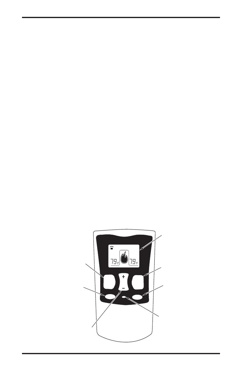
Figure 7 - Thermostat Hand-Held Remote Control Unit
LOCK
MANU AUTO
ºC/ºF
TEMP
POWER
ROOM
TEMP
SET
TEMP
AUTO
Turns Hand-Held Remote
On or Off and Allows You
to Choose the Manual
Setting
Selects AUTO Mode
°C/°F Mode Button
Locks System to
Prevent Accidental
Ignition
Turns Burners
On or Off
Increases or Decreases
Room Temperature in
AUTO Mode
Digital Display Shows
Temperature and Settings
Safety Features
When away from home for an extended period
of time or as a child safety feature to prevent
accidental ignition of thereplace, the receiver
ON/OFF/REMOTE switch should be in the OFF
position.
Auto Shutoff Feature
1. If the average room temperature reaches a
rangeof82°F(28°C)to92°F(33°C),the
hand-heldremotecontrolwillperformasafety
overrideandshutthereplaceoff.Thisfeature
is not available in the MANU mode.
2. The receiver continuously receives signals
from the hand-held remote to control the
room temperature. If the hand-held remote is
misplaced,obstructedorforanyreasoncan-
nottransmittothereceiver,thereceiverwill
shutoffthereplace.Thiswilloccurineight
or more minutes depending upon location of
remote transmitter and strength of batteries.
Key Pad Lock Feature
This feature allows the user to lock/unlock the
keypadonthehand-heldremoteintheMANUor
AUTO mode to prevent inadvertent operation (i.e.
childrenoperatingthehand-heldremotecontrol,
etc.).Thekeypadislockedineitheronoroff.Press
the POWER and LOCK buttons together to turn
the unit on or off.
2701 Industrial Drive
P.O. Box 90004
Bowling Green, KY 42102-9004
www.desatech.com
DOCKING STATION
The wall docking station offers a convenient loca-
tiontostoreyourhand-heldremotecontrolwhen
thereplaceisnotinuse.Thereplacewillnot
operateproperlywhenremotecontrolisstoredin
the wall docking station.
Note: For customer service contact DESA Heating
Products at 1-866-672-6040 or visit our web site
at www.desatech.com.
Figure 8 - Remote Docking Station
  • Page 1 1
  • Page 2 2
  • Page 3 3
  • Page 4 4
  • Page 5 5
  • Page 6 6
  • Page 7 7
  • Page 8 8

Desa CD32M User manual

Category
Fireplaces
Type
User manual

Ask a question and I''ll find the answer in the document

Finding information in a document is now easier with AI

in other languages