Yamaha TSX-100 User manual

Category
CD players
Type
User manual
CONTENTS
TO SERVICE PERSONNEL ...................................... 2–4
PREVENTION OF ELECTROSTATIC DISCHARGE .... 5
FRONT PANELS ........................................................ 6–7
REAR PANELS ........................................................ 8–10
REMOTE CONTROL PANELS .................................... 11
SPECIFICATIONS /
........................................ 11
INTERNAL VIEW ......................................................... 12
DISASSEMBLY PROCEDURES ........... 12–15
TEST MODE ................................................................. 16
................................................................... 17
BLOCK DIAGRAM ....................................................... 18
WIRING DIAGRAM ...................................................... 19
PRINTED CIRCUIT BOARDS................................ 20–26
SCHEMATIC DIAGRAMS ...................................... 27–31
REPLACEMENT PARTS LIST .............................. 32–36
REMOTE CONTROL.............................................. 37–39
101079
SERVICE MANUAL
DESKTOP AUDIO SYSTEM
2008 All rights reserved.
This manual is copyrighted by YAMAHA and may not be copied or
redistributed either in print or electronically without permission.
P.O.Box 1, Hamamatsu, Japan
'08.03
IMPORTANT NOTICE
This manual has been provided for the use of authorized YAMAHA Retailers and their service personnel.
It has been assumed that basic service procedures inherent to the industry, and more specifically YAMAHA Products, are already
known and understood by the users, and have therefore not been restated.
WARNING: Failure to follow appropriate service and safety procedures when servicing this product may result in personal
injury, destruction of expensive components, and failure of the product to perform as specified. For these reasons,
we advise all YAMAHA product owners that any service required should be performed by an authorized
YAMAHA Retailer or the appointed service representative.
IMPORTANT: The presentation or sale of this manual to any individual or firm does not constitute authorization, certification or
recognition of any applicable technical capabilities, or establish a principle-agent relationship of any form.
The data provided is believed to be accurate and applicable to the unit(s) indicated on the cover. The research, engineering, and
service departments of YAMAHA are continually striving to improve YAMAHA products. Modifications are, therefore, inevitable
and specifications are subject to change without notice or obligation to retrofit. Should any discrepancy appear to exist, please
contact the distributor's Service Division.
WARNING: Static discharges can destroy expensive components. Discharge any static electricity your body may have
accumulated by grounding yourself to the ground buss in the unit (heavy gauge black wires connect to this buss).
IMPORTANT: Turn the unit OFF during disassembly and part replacement. Recheck all work before you apply power to the unit.
TSX-100
TSX-100
2
TSX-100
TSX-100
WALL
OUTLET
EQUIPMENT
UNDER TEST
AC LEAKAGE
TESTER OR
EQUIVALENT
INSULATING
TABLE
WARNING: CHEMICAL CONTENT NOTICE!
This product contains chemicals known to the State of California to cause cancer, or birth defects or other reproductive
harm.
DO NOT PLACE SOLDER, ELECTRICAL/ELECTRONIC OR PLASTIC COMPONENTS IN YOUR MOUTH FOR ANY
REASON WHAT SO EVER!
Avoid prolonged, unprotected contact between solder and your skin! When soldering, do not inhale solder fumes or expose
eyes to solder/flux vapor!
If you come in contact with solder or components located inside the enclosure of this product, wash your hands before
handling food.
1. Critical Components Information
Components having special characteristics are marked s
and must be replaced with parts having specifications equal
to those originally installed.
2. Leakage Current Measurement (For 120V Models Only)
When service has been completed, it is imperative to verify
that all exposed conductive surfaces are properly insulated
from supply circuits.
Meter impedance should be equivalent to 1500 ohms shunted
by 0.15µF.
Leakage current must not exceed 0.5mA.
Be sure to test for leakage with the AC plug in both polarities.
All of the P.C.B.s installed in this unit and solder joints are
soldered using the lead free solder.
Among some types of lead free solder currently available,
it is recommended to use one of the following types for the
repair work.
Sn + Ag + Cu (tin + silver + copper)
Sn + Cu (tin + copper)
Sn + Zn + Bi (tin + zinc + bismuth)
Caution:
As the melting point temperature of the lead free solder is
about 30°C to 40°C (50°F to 70°F) higher than that of the lead
solder, be sure to use a soldering iron suitable to each solder.
About lead free solder /
TO SERVICE PERSONNEL
3
TSX-100
TSX-100
WARNING: Laser Safety
This product contains a laser beam component. This component may emit invisible, as well as visible radiation,
which may cause eye damage. To protect your eyes and skin from laser radiation, the following precautions must be
used during servicing of the unit.
1) When testing and/or repairing any component within the product, keep your eyes and skin more than 30 cm away from
the laser pick-up unit at all times. Do not stare at the laser beam at any time.
2) Do not attempt to readjust, disassemble or repair the laser pick-up, unless noted elsewhere in this manual.
3) CAUTION : Use of controls, adjustments or performance of procedures other than those specified herein may result in
hazardous radiation exposure.
Laser Emitting conditions:
1) When the top cover is removed, and the STANDBY/ON SW is turned to the “ON” position, the laser component will emit
a beam for several seconds to detect if a disc is present. During this time (5-10 sec.) the laser may radiate through the
lens of the laser pick-up unit. Do not attempt any servicing during this period!
If no disc is detected, the laser will stop emitting the beam. When a disc is loaded, you will not be exposed to any laser
emissions.
2) The laser power level can be adjusted with the VR on the pick-up PWB, however, this level has been set by the factory
prior to shipping from the factory. Do not adjust this laser level control unless instruction is provided elsewhere in this
manual. Adjustment of this control can increase the laser emission level from the device.
CAUTION
Danger of explosion if battery is incorrectly replaced.
Replace only with the same or equivalent type.
WARNING: Lithium batteries
WARNING: Lithium batteries are dangerous because
they can be exploded by improper handling. Observe the
following precautions when handling or replacing lithium
batteries.
Leave lithium battery replacement to qualified service
personnel.
Always replace with batteries of the same type.
When installing on the PC board by soldering, solder
using the connection terminals provided on the battery
cells. Never solder directly to the cells. Perform the
soldering as quickly as possible.
Never reverse the battery polarities when installing.
Do not short the batteries.
Do not attempt to recharge these batteries.
Do not disassemble the batteries.
Never heat batteries or throw them into fire.
ADVARSEL!
Lithiumbatteri –Eksplosionsfare ved fejlagtig håndtering.
Udskiftning må kun ske med batteri af samme fabrikat og
type. Levér det brugte batteri tilbage til leverandøren.
VARNING
Explosionsfara vid felaktigt batteribyte. Använd samma
batterityp eller an ekvivalent typ som rekommenderas av
apparattillverkaren. Kassera använt batteri enligt
fabrikantens instruktion.
VAROITUS
Paristo voi räjähtää, jos se on virheellisesti asennettu.
Vaihda paristo ainoastaan laitevalmistajan suosittelemaan
tyyppiin. Hävitä käytetty peristo valmistajan ohjeiden
mukaisesti.
4
TSX-100
TSX-100
Type GaAlAs
Wave length 780 nm
Emission duration continuous
Warning for power supply
The primary side of the power supply carries live mains voltage when the player is connected to the mains even when
the player is switched off !
This primary area is not shielded so it is possible to touch copper tracks and/or components when servicing the player.
Service personnel have to take precautions to prevent touching this area or components in this area.
Note:
The screws on the DVD mechanism may never be touched, removed or re-adjusted.
Handle the DVD mechanism with care when the unit has to be exchanged!
The DVD mechanism is very sensitive for dropping or giving shocks.
Laser Diode Properties
Laser output max. 44.6 µW *
* This output is the value mea-
sured at a distance of about
200 mm (7.9 in) from the ob-
jective lens surface on the
optical pick-up block.
5
TSX-100
TSX-100
PREVENTION OF ELECTROSTATIC DISCHARGE
Some semiconductor (solid state) devices can be damaged easily by static electricity. Such components commonly are called
Electrostatically Sensitive (ES) Devices. Examples of typical ES devices are integrated circuits and some field-effect transis-
tors and semiconductor “chip” components. The following techniques should be used to help reduce the incidence of compo-
nent damage caused by electro static discharge (ESD).
1. Immediately before handling any semiconductor component or semiconductor-equipped assembly, drain off any ESD on
your body by touching a known earth ground. Alternatively, obtain and wear a commercially available discharging ESD wrist
strap, which should be removed for potential shock reasons prior to applying power to the unit under test.
2. After removing an electrical assembly equipped with ES devices, place the assembly on a conductive surface such as
aluminum foil, to prevent electrostatic charge buildup or exposure of the assembly.
3. Use only a grounded-tip soldering iron to solder or unsolder ES devices.
4. Use only an anti-static solder removal device. Some solder removal devices not classified as “anti-static (ESD protected)”
can generate electrical charge sufficient to damage ES devices.
5. Do not use freon-propelled chemicals. These can generate electrical charges sufficient to damage ES devices.
6. Do not remove a replacement ES device from its protective package until immediately before you are ready to install it. (Most
replacement ES devices are packaged with leads electrically shorted together by conductive foam, aluminum foil or compa-
rable conductive material).
7. Immediately before removing the protective material from the leads of a replacement ES divice, touch the protective mate-
rial to the chassis or circuit assembly into which the device will be installed.
CAUTION: Be sure no power is applied to the chassis or circuit, and observe all other safety precautions.
8. Minimize bodily motions when handling unpackaged replacement ES devices. (Otherwise harmless motion such as brush-
ing together of your fabric clothes or lifting of your foot from a carpeted floor can generate static electricity (ESD) sufficient
to damage an ES device).
Grounding for electrostatic breakdown prevention
1. Human body grounding.
Use the antistatic wrist strap to discharge the static electricity from your body.
2. Work table grounding.
Put a conductive material (sheet) or steel sheet on the area where the optical pickup is placed and ground the sheet.
Caution:
The static electricity of your clothes will not be grounded through the wrist strap. So take care not to let your clothes touch the
optical pickup.
1M-ohms
Conductive material
(sheet) or steel sheet
Anti-static wrist strap
6
TSX-100
TSX-100
iPod port
USB port
FRONT PANELS
Top view
R, B, G models
U, A, J models
8
TSX-100
TSX-100
B model
REAR PANELS
Rear view
U model
R, A, G, J models
PHONES
PORTABLE
TSX-100
11
– Silver color –
Player Section /
Playback system /
.................................................................................. CD, CD-R/RW
Amplifier Section /
Type / ................................................. Twin SR-Bass
Magnetic shielding type /
Driver / ....................................... 4.5 cm (1-3/4")
Titanium cone full-range x 2
Minimum RMS output power per channel / (EIAJ)
..................................................................................... 10 W + 10 W
Input sensitivity/Impedance /
U, R, A, B, J models
PORTABLE ..................................................... 300 mV/47 k-ohms
G model
AUX ................................................................. 300 mV/47 k-ohms
Output level/Impedance /
PHONES (volume max.)
U, R, A, G models ..................................................... 1 V/32 ohms
B, J models ........................................................... 470 V/32 ohms
iPod Section / [U, A, J models]
Support iPod models /
.............. iPod (Click and wheel), iPod mini, iPod nano, iPod touch
FM Tuner Section /
Tuning range /
U model ............................................................... 87.5 to 107.9 MHz
R, A, B, G models ........................................... 87.50 to 108.00 MHz
J model ............................................................... 76.0 to 108.0 MHz
AM Tuner Section /
Tuning range /
U model ................................................................. 530 to 1,710 kHz
R, A, B, G, J models ............................................. 522 to 1,629 kHz
DAB Tuner Section [B model]
Tuning range (BAND III) ................................. 174 MHz to 240 MHz
Sensitivity ................................................................................ -95 dB
Selectivity (for adjacent channel) .......................................... 40 dB
Antenna input (unbalanced) .............................................. 50 ohms
General /
Power supply /
U model ................................................................AC 120 V, 60 Hz
R, A, B, G, J models ................................ AC 100-240 V, 50/60 Hz
Power consumption
................................................................................................. 20 W
Standby power consumption
.................................................................................... 1.0 W or less
Dimensions (W x H x D)
..................... 300 x 141.5 x 200 mm (11-13/16” x 5-9/16” x 7-7/8”)
Weight
........................................................................ 2.7 kg (5 lbs. 15 oz.)
Finish
Black color .................................................. U, R, A, B, G, J models
Silver color .................................................. U, R, A, B, G, J models
Accessories
Remote control x 1, Battery (Lithium, CR2025) x 1, AM loop antenna
(2.0 m) x 1, Indoor FM antenna (1.5 m) x 1, Power cable (2 m) x 1,
Indoor DAB antenna (2.0 m) x 1 (B model)
SPECIFICATIONS /
U .......... U.S.A. model
R .......... General model
A .......... Australian model
B .......... British model
G .......... European model
J ........... Japanese model
DIMENSIONS /
Unit: mm (inch)
300
(11-13/16")
141.5
(5-9/16")
200
(7-7/8")
Swing Radiator Bass ™” is a trademark of YAMAHA CORPORATION.
iPod is a trademark of Apple Inc., registered in the U.S. and other coun-
tries.
R
The XM name and related logos are registered trademarks of XM Satellite
Radio Inc.
This receiver supports DAB tuning.
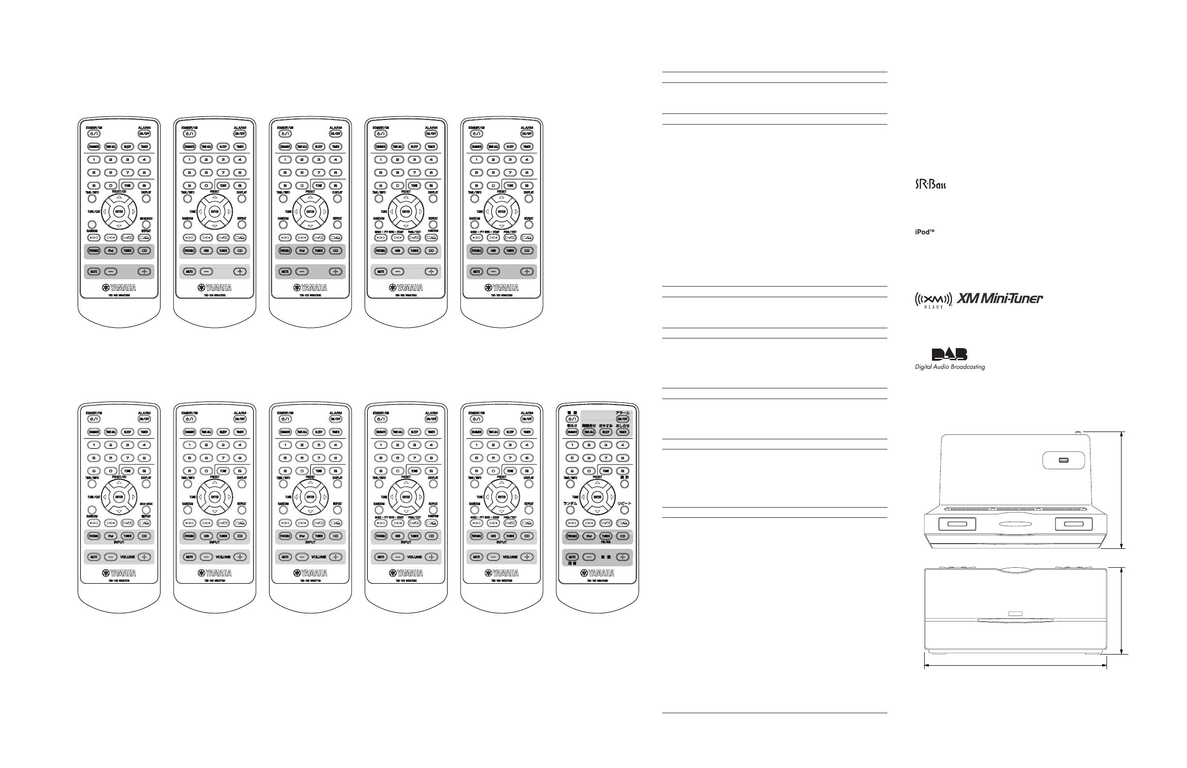
REMOTE CONTROL PANELS
Black color
U model R model A model B model G model
U model R model A model B model G model J model
* Specifications are subject to change without notice due to product
improvements.
TSX-100
12
2
2
6
4
6
2
1
5
5
Front panel unit
CN83
CN18
CN17
CN82
Speaker L ass'y
CN84
CN85
Speaker R ass'y
Rear cabinet ass'y
3
Ground lead
INTERNAL VIEW
321 4 5
1
2
3
4
5
6
7
8
9
0
A
B
C
D
SPEAKER L ASS'Y
SMPS P.C.B.
MAIN (1) P.C.B.
MAIN (4) P.C.B. (U, A, J models)
MAIN (6) P.C.B. (R, B, G models)
DAB MODULE (B model)
MAIN (7) P.C.B. (B model)
AM/FM TUNER MODULE
MAIN (2) P.C.B.
SPEAKER R ASS'Y
MAIN (8) P.C.B.
MAIN (3) P.C.B.
MAIN (5) P.C.B.
MAIN (9) P.C.B.
MAIN (10) P.C.B.
CD MECHANISM UNIT
7
8
09BA
DC
6
Fig. 1
1. Removal of Rear Cabinet Assy
a. Remove 2 screws (1) and 6 screws (2). (Fig. 1)
b. Pull out the rear cabinet rearward slowly. (Fig. 1)
c. Remove CN17. (Fig. 1)
d. Remove screw (3) and then remove the ground lead.
(Fig. 1)
e. Remove the rear cabinet assy. (Fig. 1)
2. Removal of Front Panel Unit
a. Remove 2 screws (4). (Fig. 1)
b. Remove CN18, CN82 and CN84. (Fig. 1)
c. Remove the front panel unit forward. (Fig. 1)
3. Removal of Speaker L Assy and Speaker R Assy
a. Remove 3 screws (5). (Fig. 1)
b. Remove CN83. (Fig. 1)
c. Remove the speaker L assy. (Fig. 1)
d. Remove 3 screws (6). (Fig. 1)
e. Remove CN85. (Fig. 1)
f. Remove the speaker R assy. (Fig. 1)
1 2
3
4
5
6
Top view
Front view
DISASSEMBLY PROCEDURES /
(Remove parts in the order as numbered.)
Disconnect the power cable from the AC outlet.
Safety Measures
Some internal parts in this product contain high volt-
ages and are dangerous. Be sure to take safety mea-
sures during servicing, such as wearing insulating
gloves.
C971 on the SMPS (2) P.C.B. is dangerous even after
the power is turned off because an electric charge re-
mains and a high voltage continues to exist there.
Before starting any repair work, perform discharge by
connecting a discharge resistor (5k-ohms/10 W) be-
tween terminals of the capacitor. The time required for
discharging is about 30 seconds.
After the repair work, also perform discharge in the
same manner.
13
TSX-100
TSX-100
Fig. 3
CD mechanism unit
CD mechanism unit
Flexible flat cable
AM/FM tuner module
CN95
CN35
CN15
(B model)
CN12
CN91
CN92
CN31
CN31
CN33
CN32
CN93
MAIN (1) P.C.B.
CN42
CN11
8
9
7
0
0
0
CN31
OK NG
*
4. Removal of AM/FM Tuner Module
a. Remove 2 screws (7). (Fig. 2)
b. Remove CN12. (Fig. 2)
c. Remove the AM/FM tuner module. (Fig. 2)
5. Removal of MAIN(1) P.C.B.
a. Remove 4 screws (8) and screw (9). (Fig. 2)
b. Remove CN11, CN35, CN42, CN91-93 and CN95.
(Fig. 2)
c. Remove CN15. (Fig. 2) (B model)
d. Remove the MAIN (1) P.C.B.. (Fig. 2)
6. Removal of CD Mechanism Unit and Optical
Pick-Up
a. Remove 4 screws (0). (Fig. 2)
b. Remove CN31-33. (Fig. 2)
c. Lift up the rear side of the CD mechanism unit, then
remove it rearward. (Fig. 2)
*
When installing the CD mechanism unit, install the
flexible flat cable as shown in Fig. 3.
7
8 9
0
Fig. 2
14
TSX-100
TSX-100
Fig. 4
d. Remove 4 screws (A) and then remove the drive unit.
(Fig. 4)
e. Remove flexible flat cable. (Fig. 4)
f. Remove stopper gear A and then remove the gear A.
(Fig. 4)
g. Remove stopper sled shaft and then remove the sled
shaft. (Fig. 4)
h. Remove the optical pick-up unit. (Fig. 4)
* Never touch the potentiometer installed to the opti-
cal pick-up unit. (Fig. 5)
A
A
A
CD mechanism unit
Drive unit
Flexible flat cable
Optical pick-up unit
Sled shaft
Stopper sled shaft
Stopper gear A
Gear A
Optical pick-up unit
Potentiometer
Fig. 5
15
TSX-100
TSX-100
How to manually eject a disc
If the inserted disc cannot be ejected, it is possible to
eject it manually.
a. Remove the CD mechanism unit. (Refer to Disas-
sembly Procedures)
b. Turn the loading gear in the arrow direction until the
disc is ejected. (Fig. 6)
CD mechanism unit
Left side
Loading gear
Disc
Fig. 6
16
TSX-100
TSX-100
TEST MODE
The firmware version is displayed.
Starting Service Mode
a. Connect the power cable of this unit to the AC power outlet.
b. Press the “INPUT/SNOOZE” key of this unit to turn on the power.
c. Press the “INPUT/SNOOZE” key of this unit repeatedly to select the CD.
Make sure that [No Disc] is displayed.
* While the disc is being played, press the “
AA
AA
A
/
FF
FF
F
(STOP/EJECT)” key to eject the disc.
d. While pressing the “MUTE” key of this unit, press the “
AA
AA
A
/
FF
FF
F
(STOP/EJECT)” key of this unit.
The SERVICE mode is activated and each firmware version is displayed at about 5 seconds intervals.
e. Press the “POWER OFF” key of this unit to turn off the power.
f. Disconnect the power cable of this unit from the AC power outlet.
Starting Factory Reset
All settings are returned to initial settings.
a. Activate the Service Mode.
b. While the firmware versions are displayed, press and hold the “INPUT/SNOOZE” key for longer than 4 seconds.
c. [FACTORY SET] is displayed and the power is turned off automatically in about 4 seconds.
HOSTHOST
HOSTHOST
HOST
VERVER
VERVER
VER
071018-03U/U071018-03U/U
071018-03U/U
SERVICESERVICE
SERVICESERVICE
SERVICE
MODEMODE
MODEMODE
MODE
DSPDSP
DSPDSP
DSP
VERVER
VERVER
VER
0707
0707
07
1010
1010
10
1616
1616
16
0101
0101
01
This is displayed when the SERVICE mode is activated.
The firmware version of the main microprocessor is displayed.
The firmware version of DSP is displayed.
The firmware version of USB is displayed.
(R, B, G models)
The firmware version of DAB is displayed.
(B model)
Ordinary display.
USBUSB
USBUSB
USB
VERVER
VERVER
VER
xxxx
xxxx
xx
xxxx
xxxx
xx
xxxx
xxxx
xx
xxxx
xxxx
xx
Destination
About 5 seconds
About 5 seconds
DABDAB
DABDAB
DAB
VERVER
VERVER
VER
xxxx
xxxx
xx
xxxx
xxxx
xx
xxxx
xxxx
xx
xxxx
xxxx
xx
3:53PM3:53PM
3:53PM3:53PM
3:53PM
NoNo
NoNo
No
DiscDisc
DiscDisc
Disc
About 5 seconds
About 5 seconds
2
ABCDEFGH I J
1
3
4
5
7
TSX-100
6
18
CD MECHANISM UNIT
AM/FM
iPod
RDS_DATA
ADL_SDTO
HP_ON
SP_ON
AMP13V
POWER H
+3.3VD
+5VD
R, A, G, J models
U, B models
CD_SDTO1
DAB/XM_SDTO
XM_SDTO
DAB_SDTO
USBD+/-
SENSOR
KEY0-2
BEEP
V_PROTECT
AM/FM
TUNER
iPod DOCK
(U, A, J models)
USB (R, B, G models)
XM
(U model)
DAB
(B model)
AC
AMP13V
REMOTE
MICROPROCESSOR
MICROPROCESSOR
MICROPROCESSOR
MICROPROCESSOR
MICROPROCESSOR
(MAIN)
(AMP)
AC IN
PHONES
L
SPEAKERS
R
U, A, J models
JK61
JK71
JK41
RC82
IC61
IC21
IC14
IC15
IC53
RY52
RY51
IC16
IC51
IC52
IC22
IC71
IC41
IC31
IC33
27,28
1,3
1,73,5
3,5
1,2
2
4
2-5
53
4
6
16,17
8,9
3
14
29-32
2
3
3,13
9
1,7
37
79,80
62
5,11
9,10
91
88 35
13
12
99
6
9
69
70
3,5,10,11
60,61,65,66
85-87,95-98
27
2,15
1,12
4,11
5,14
U model
B model
R, B, G models
ROOM
SENSOR
RC81
S801-813
IC12
IC11
FL81
REMOTE
PANEL KEYS
SMPS
• See page 31
SCHEMATIC DIAGRAM
MAIN
• See page 27-30
SCHEMATIC DIAGRAM
BLOCK DIAGRAM
ABCDEFGH I J
1
2
3
4
5
6
7
TSX-100
19
WIRING DIAGRAM
SPEAKER R ASS'Y SPEAKER L ASS'Y
B model
R, B, G models
CD MECHANISM
UNIT
AM/FM TUNER
MODULE
MAIN (5) P.C.B.
MAIN (3) P.C.B.
MAIN (10) P.C.B.
MAIN (8) P.C.B.
MAIN (1) P.C.B.
MAIN (2) P.C.B.
MAIN (6) P.C.B.
(Writing port)
MAIN (4) P.C.B.
MAIN (7) P.C.B.
MAIN (9) P.C.B.
SMPS P.C.B.
U, A, J models
(Writing port)
2
ABCDEFGH I J
1
3
4
5
7
TSX-100
6
20
MAIN (1)
MAIN (8)
CN82
MAIN (9)
CN84
SMPS
CN93
(Top view)
AM/FM TUNER MODULE
MAIN (2)
BN11
MAIN (7)
BN15
MAIN (2)
BN42
MAIN (4) BN16 (U, A, J models)
(R, B, G models)
(B model)
MAIN (6) BN17
MAIN (2)
BN35
MAIN (3)
BN18
AC IN
SMPS
CN91
SMPS
CN92
PORTABLE PHONES XM
U model
B model
BAT1: 30H3A3H (B, G models)
CAUTION
Danger of explosion if battery is incorrectly replaced.
Replace only with the same or equivalent type.
Note) The electrical parts available as servicing parts are those in the replacement parts list only.
When replacement of any electrical part other than those in the list is necessary, replace the P.C.B.
assembly which includes that part.
PRINTED CIRCUIT BOARDS
2
ABCDEFGH I J
1
3
4
5
7
TSX-100
6
22
MAIN (2) (Top view) MAIN (2) (Bottom view)
CD MECHANISM
UNIT
CD MECHANISM
UNIT
CD MECHANISM
UNIT
(Writing port)
MAIN (1)
CN35
MAIN (1)
CN42
MAIN (1)
CN11
(Writing port)
2
ABCDEFGH I J
1
3
4
5
7
TSX-100
6
26
MAIN (1)
BN91
MAIN (1)
BN93
MAIN (1)
BN92
SMPS
(Side A) SMPS (Side B)
5 k-ohms
10 W
Safety Measures
Some internal parts in this product contain high voltages and are dangerous. Be sure to take safety measures during servicing, such as
wearing insulating gloves.
C971 on the SMPS (2) P.C.B. is dangerous even after the power is turned off because an electric charge remains and a high voltage
continues to exist there.
Before starting any repair work, perform discharge by connecting a discharge resistor (5k-ohms/10 W) between terminals of the capaci-
tor. The time required for discharging is about 30 seconds.
After the repair work, also perform discharge in the same manner.
ABCDEFGH I J
1
2
3
4
5
6
7
TSX-100
27
iPod IN
SPEAKER OUT
USB IN
MAIN (4)
MAIN (1)
U model
SPEAKERS L
ASS'Y
SPEAKERS R
ASS'Y
B model
U, A, J models
iPod
XM
MAIN (7)
MAIN (5)
MAIN (9)
MAIN (10)
MAIN (8)
MAIN (3)
MAIN (6)
USB
to MAIN (1)_CN17
Page 28
B6
to MAIN (1)_CN18
Page 28
B4
B6
to MAIN (1)_CN15
Page 28
F7
to MAIN (1)_CN17
Page 28
to MAIN (1)_BN82
Page 28
J2
to MAIN (1)_BN84
Page 28
J2
SCHEMATIC DIAGRAMS
MAIN 1/4
Note) The electrical parts available as servicing parts are those in the replacement parts list only.
When replacement of any electrical part other than those in the list is necessary, replace the P.C.B.
assembly which includes that part.
Components having special characteristics are marked s and must be replaced with parts
having specifications equal to those originally installed.
Schematic diagram is subject to change without notice.
s
2
ABCDEFGH I J
1
3
4
5
7
TSX-100
6
28
USB IN
iPod IN
PORTABLE IN
ANALOG IN
AD IN
CD/USB IN
MIX IN
SPEAKER OUT
MAIN (1)
MICROPROCESSOR
BAT1: 30H3A3H (B, G models)
CAUTION
Danger of explosion if battery is incorrectly replaced.
Replace only with the same or equivalent type.
to MAIN (3)_BN18
to AM/FM TUNER MODULE
PHONES
PORTABLE
Page 27
G3
to MAIN (4)_BN16
(U, A, J models)
Page 27
E3
to MAIN (6)_BN17
(R, B, G models)
Page 27
I5
to MAIN (2)_BN42
Page 29
G7
to MAIN (2)_BN11
Page 29 E2
to MAIN (7)_BN15
(B model)
Page 27
H7
to MAIN (2)_BN35
Page 29
B3
to MAIN (9)_CN84
Page 27
I4
to MAIN (8)_CN82
Page 27
G4
to SMPS_CN93
Page 31
H3
to MAIN (1)_CN97
Page 30
I3
to MAIN (1)_CN98
Page 30
I4
MAIN 2/4
Components having special characteristics are marked s and must be replaced with parts
having specifications equal to those originally installed.
Schematic diagram is subject to change without notice.
s
  • Page 1 1
  • Page 2 2
  • Page 3 3
  • Page 4 4
  • Page 5 5
  • Page 6 6
  • Page 7 7
  • Page 8 8
  • Page 9 9
  • Page 10 10
  • Page 11 11
  • Page 12 12
  • Page 13 13
  • Page 14 14
  • Page 15 15
  • Page 16 16
  • Page 17 17
  • Page 18 18
  • Page 19 19
  • Page 20 20
  • Page 21 21
  • Page 22 22
  • Page 23 23
  • Page 24 24
  • Page 25 25
  • Page 26 26
  • Page 27 27
  • Page 28 28
  • Page 29 29
  • Page 30 30
  • Page 31 31
  • Page 32 32
  • Page 33 33
  • Page 34 34
  • Page 35 35
  • Page 36 36
  • Page 37 37
  • Page 38 38
  • Page 39 39
  • Page 40 40

Yamaha TSX-100 User manual

Category
CD players
Type
User manual

Ask a question and I''ll find the answer in the document

Finding information in a document is now easier with AI

in other languages