Abus AZ4000/05 Installation Instructions Manual
- Category
- Security access control systems
- Type
- Installation Instructions Manual
This manual is also suitable for
Page is loading ...
Page is loading ...
Page is loading ...
Page is loading ...
Page is loading ...
Page is loading ...
Page is loading ...
Page is loading ...
Page is loading ...
Page is loading ...
Page is loading ...
Page is loading ...
Page is loading ...
Page is loading ...
Page is loading ...
Page is loading ...
Page is loading ...
Page is loading ...
Page is loading ...
Page is loading ...
Page is loading ...
Page is loading ...
Page is loading ...
Page is loading ...
Page is loading ...
Page is loading ...
Page is loading ...
Page is loading ...
Page is loading ...
Page is loading ...
Page is loading ...
Page is loading ...
Page is loading ...
Page is loading ...
Page is loading ...
Page is loading ...
Page is loading ...
Page is loading ...
Page is loading ...
Page is loading ...
Page is loading ...
Page is loading ...
Page is loading ...
Page is loading ...
Page is loading ...
Page is loading ...
Page is loading ...
Page is loading ...
Page is loading ...
Page is loading ...
Page is loading ...
Page is loading ...
Page is loading ...
Page is loading ...
Page is loading ...
Page is loading ...
Page is loading ...
Page is loading ...
Page is loading ...
Page is loading ...
Page is loading ...
Page is loading ...
Page is loading ...
Page is loading ...
Page is loading ...
Page is loading ...
Page is loading ...
Page is loading ...
Page is loading ...
Page is loading ...
Page is loading ...
Page is loading ...
Page is loading ...
Page is loading ...
Page is loading ...
Page is loading ...

UK UK
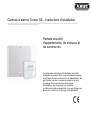
Intruder alarm panel Terxon SX – Installation istructions
Perfect Security for
home and office
These installation instructions are an important product
accessory. They contain important installation and
operation information. Bear this in mind if you pass the
product on to others. Store these installation
instructions in a safe place for future reference.
For a list of contents with page numbers, see page 3.

UK UK
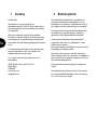
1 Introduction
Dear Customer,
Thank you for purchasing the Burglar Alarm Panel
Terxon SX. You have purchased a product that has been
designed and constructed according to the state-of-the-
art,
which complies with the current standards of domestic
and European regulations. The CE has been proven and
all related certifications are available from the
manufacturer upon request (www.abus-sc.eu).
To maintain this status and to guarantee safe operation, it
is your obligation to observe these installation instructions.
In the event of questions, please contact your local
specialist dealer.
ABUS Security-Center GmbH & Co. KG
86444 Affing
GERMANY
www.abus-sc.eu
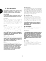
2 Usage in accordance with
regulations
This burglar alarm panel uses detectors and transmitters
to secure your property. You can use it to protect your
company, house, garage, garden house, weekend
cottage, etc.
The alarm centre registers unauthorised break-ins by
switching output contacts to which you can connect visual,
acoustic or silent alarm transmitters.
The alarm centre contacts and connected components
must be kept free of moisture (bathrooms and similar
surroundings are to be strictly avoided).
Use of this product for other than the described purpose
may lead to damage of the product.
Other hazards such as short-circuiting, fire, electric shock,
etc., are also possible. The power unit is designed for
operation with mains electricity at 230 Volt AC / 50 Hz.
No part of the product may changed or modified in any
way.
Connection to the public power network is subject to
country-specific regulations. Please be aware of
applicable regulations in advance.

3
UK
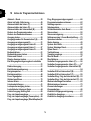
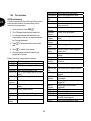
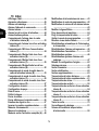
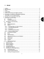
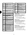
3 Contents
1 Introduction........................................................................................................................................2
2 Usage in accordance with regulations ..............................................................................................2
3 Contents ............................................................................................................................................3
4 Precautions........................................................................................................................................5
5 Scope of delivery and accessories required ......................................................................................6
6 Notes on connection and extension options ......................................................................................7
7 Notes on security system...................................................................................................................8
8 Overview of housing components....................................................................................................10
9 Notes on installation ........................................................................................................................12
9.1 Alarm centre .............................................................................................................................12
9.2 Control units .............................................................................................................................12
10 Notes on wiring................................................................................................................................13
10.1 Alarm centre .............................................................................................................................13
10.2 Control units .............................................................................................................................14
10.3 Detectors ..................................................................................................................................16
10.3.1 Door and window contacts ................................................................................................16
10.3.2 Infrared sensitivity detector................................................................................................16
10.3.3 Smoke detector .................................................................................................................17
10.3.4 Acoustic glass breakage sensor:.......................................................................................17
10.3.5 Passive glass breakage sensor:........................................................................................17
10.4 Outdoor siren and flashlight......................................................................................................18
10.5 Dialler .......................................................................................................................................19
10.6 Key switch ................................................................................................................................19
10.7 Fitting and connecting a loudspeaker .......................................................................................20
10.8 Relay module............................................................................................................................20
10.9 Resistors ..................................................................................................................................20
10.10 Walk test ...............................................................................................................................21
10.11 Detector alarm memory ........................................................................................................21
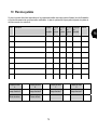
11 Term declaration..............................................................................................................................22
12 General terms..................................................................................................................................23
13 Specimen Installation.......................................................................................................................24
14 First-time usage...............................................................................................................................30
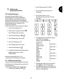
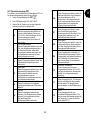
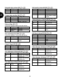
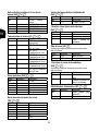
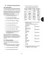
15 Programming ...................................................................................................................................31
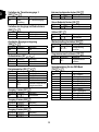
15.1 Program mode..........................................................................................................................31
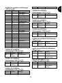
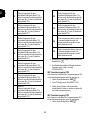
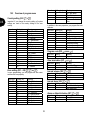
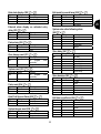
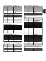
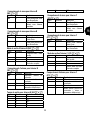
15.2 Overview of program menu ......................................................................................................32
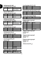
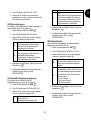
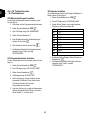
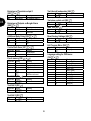
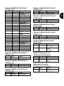
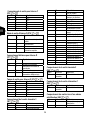
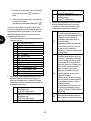
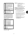
15.3 Settings in program menu ........................................................................................................39

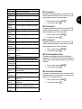
4
UK
15.4 Test functions ...........................................................................................................................62
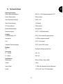
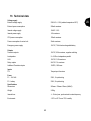
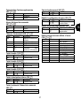
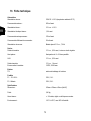
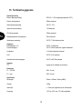
16 Technical data .................................................................................................................................65
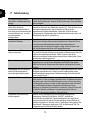
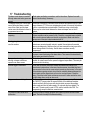
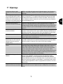
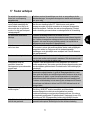
17 Troubleshooting...............................................................................................................................66
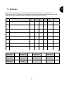
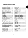
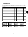
18 Index of Programming Functions.....................................................................................................67
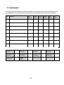
19 System plan.....................................................................................................................................68

5
UK
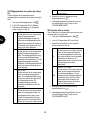
4 Precautions
!WARNING!
To avoid fire and injury, please
observe the following:
x Securely fasten the device at a
dry location in the building.
x Ensure sufficient air circulation for
the alarm centre.
x Do not expose the device to
temperatures less than -10°C or
more than 55°C.
x The device is designed for indoor
use only.
x Humidity must not exceed 90%
(non-condensed).
x Make sure that no metal objects
can be pushed into the equipment
from outside.
x Ensure that the voltage is
disconnected when performing
work on the device.
!ATTENTION!
Please observe the following
regulations to ensure trouble-free
operation of your device.
x The alarm centre is supplied with
12V DC power by means of the
internal transformer.
x The transformer is connected to
the 230VAC building mains by
means of a separate, electrically
protected line.
x Connection work to the building
mains is subject to country-
specific regulations.
x A 7Ah rechargeable battery
supplies emergency standby
power.
x The maximum power
consumption of connected
components must never exceed
1A.
x Always replace fuses with fuses
of the same rating, never higher.
!IMPORTANT INFO!
Burglar alarm panels in general:
If the equipment is not correctly
installed, signals may be
misinterpreted and result in false
alarms.The costs resulting from the
deployment of rescue organisations,
e.g.:fire or police, are borne by the
operator of the equipment.
Therefore please read the
instructions very carefully and follow
the installation instructions for lines
and components precisely.

6
UK
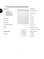
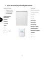
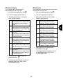
5 Scope of delivery and accessories required
Scope of delivery
x Intruder alarm panel
(alarm centre)
x LCD operating panel
x Installation Instructions
x Operating instructions
You also need:
Alarm detector
Signal transmitter
12V/7Ah rechargeable battery
Distributor
Cables
Optionally available:
Relay module
Required tools:
Flat screwdriver (small)
Philips screwdriver
Drill
6mm drill bit
4mm drill bit
6mm screws
4mm screws
Wallplugs, filler, etc.
Soldering iron and solder
Insulation tape or shrink-on tubing
Voltmeter, ohmmeter (or
multimeter)
Cable channel
Screw-clamps

7
UK
6 Notes on connection and extension options
The burglar alarm panel is the basic device of an
electronic security system for protecting your property
(e.g.: apartment, house, garage, shops, etc.). In
combination with other components such as detectors and
signal transmitters, it secures the areas to be monitored.
The alarm is triggered by unauthorised break-in attempts.
The alarm centre is operated by means of the connected
control unit. This enables the alarm centre to be installed
at a hidden location. Up to 4 control units can be
connected. Furthermore, the alarm centre can be
operated via a so-called key switch.
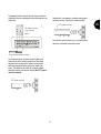
The burglar alarm panel has 9 separately evaluated alarm
zones. The alarm centre monitors whether a (minimal)
quiescent current is flowing or not between the two
contacts (CCT) of each alarm zone. If you make a contact
between the alarm zone contacts, this is treated as closed
and a current flow is possible. If no contact exists, no
current flow is possible and the alarm zone is open. Any
changes trigger an alarm, depending on the programming.
Differential monitoring of the alarm zones is also possible
(DEOL).
Properties of the alarm centre:
x 8 freely programmable alarm zones, all of which can be
programmed as follows:
Immediate, delayed, access, panic, 24 hour, fire,
technical or time
x 1 tamper zone for connected detectors
x 1 tamper zone for connected signal transmitters
x 3 transistor outputs that can be configured for a specific
event (alarm, fire, panic,…)
x Integrated transformer (230V AC / 12V DC) for
supplying the alarm centre and connected detectors and
for recharging the battery
x Standby power supply via a 12V/7Ah battery
x Simple programming and operation via 1–4 control units
x The state of the alarm zones and the alarm centre is
displayed on a plain-text display.
x Zone blocking as a way of temporarily removing
individual alarm zones from surveillance
x Tamper contacts for the alarm centre and the control
units
x Alarm and event memory

8
UK
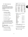
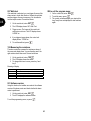
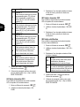
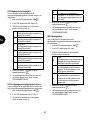
7 Notes on security system
The Terxon SX burglar alarm panel enables you to
configure each of the 8 alarm zones optimally to suit
your operating conditions. Recommendations:
x Distribute the external detectors in as small groups as
possible to the zones (e.g., ground-floor detector to
zone 1, etc.); activate detectors singly; if possible, use
all zones of the alarm centre.
x The acoustic signal (siren) of the signal transmitter
should be shorter than the visual signal (flashlight).
Alarm times must be set according to local regulations.
(E.g., in Germany, the acoustic alarm must be limited to
3 minutes.)
x The delay time should not be finally set until a practical
test has been conducted.
x Only persons of trust should be given the code.
x When operating the alarm centre, enter the code in such
a way that it is concealed from persons standing nearby.
x The cable recommended for connecting the
components (minimum diameter: 0.6 mm/wire) is
normally colour-coded.
The user and program codes must be different.
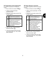
For reasons of clear layout, use the following colour
coding:
Red: +12V voltage supply
Black: 0V ground
Yellow: Alarm contact
Green: Alarm contact
Brown: Tamper contact
White: Tamper contact
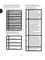
x Use distributors when connecting more than one
detector to an alarm zone. Cable extensions can be
soldered or screwed together. Ensure good insulation
(insulating tape, shrink-on tubing) to avoid short-
circuiting and false alarms. See the illustration on the
next page.
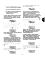
x Proceed as follows:
1. Read the operating instructions carefully.
2. Draw up a plan of the object that includes the
installation location of the detectors and the alarm
centre and all cables required.
3. Lay the cables as required.
4. Install the detectors and the alarm centre.
5. Connect the cables to the detectors and the alarm
centre.
6. Connect the power supply (battery, mains).
7. Program the device.

9
UK
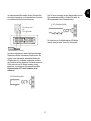
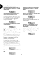
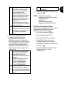
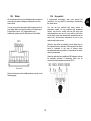
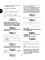
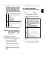
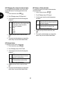
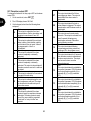
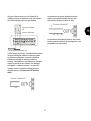
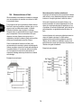
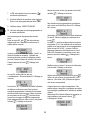
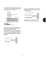
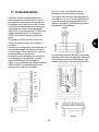
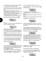
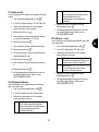
The diagram below shows the correct usage of soldered
distributors when connecting more than one detector to an
alarm zone:
As mentioned above, the alarm centre evaluates the
alarm zones via the existing current flow. Most alarm
detectors are normally closed, which means that the
detectors interrupt the alarm zone in the event of an
alarm. The detectors are called NC (normally closed)
detectors and are connected as follows (the CCT jumper
must be removed):
Sometimes it is necessary to combine several alarm
contacts in a zone. Connect the contacts serially.
NO (normally open) contacts (e.g., for panic buttons)
cannot be connected to this alarm centre.
Verteiler
NC-Alarmkontakt
(z.B. Öffnungsmelder)
A
nschlusskabel zur Zentrale
NC alarm contact
NC alarm contact
(e.g. contact
switch
Connection cable to alarm
t
NC alarm contact

10
UK
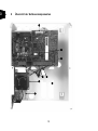
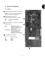
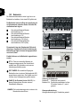
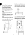
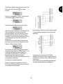
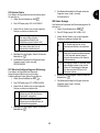
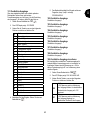
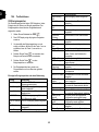
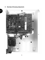
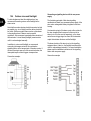
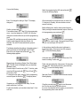
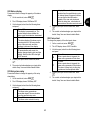
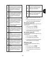
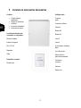
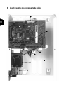
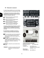
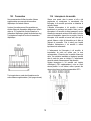
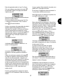
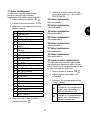
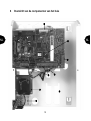
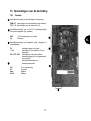
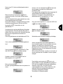
8 Overview of housing components
M
N
O
P
R
Q
S
T

11
UK
M
Connection of 230V mains supply with primary fuse (T 250V 250mA).
N
230V AC / 12V DC transformer.
O
Terminal connector strip for siren, flashlight, programmable output, loudspeaker, 12V DC power supply
and alarm zones.
P
Tamper contact of alarm panel housing.
Q
Terminal connector strip for standby battery.
R
Terminal connector strip for control units.
S
Terminal connector strip for extra transistor outputs or the optional relay module.
T
Room for 12V standby battery (7Ah) and cabling.
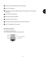
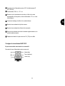
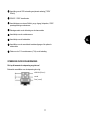
Note for 230 V connection
Do not switch on the mains power yet!
Connect the mains power to the terminal connector strip as follows:
n
Phase (black)
ground (green/yellow)

12
UK
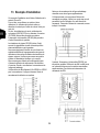
9 Notes on installation
9.1 Alarm centre
Fix the alarm centre to a flat, dry, vibration-free and heat-
resistant surface. The cables for the power supply of the
alarm centre, the alarm zones and the signalling
equipment (siren, flashlight, any external loudspeakers,
etc.) should be inconspicuous, if possible below the
surface or in a cable channel.
x Open the alarm centre housing (loosen the screws with
a Philips screwdriver and remove the cover).
x The alarm centre’s PCB is fixed in the housing with
three screws. Loosen these screws and remove the
PCB. The transformer plug can be disconnected from
the PCB.
x Use the housing as a template to make drill-marks for
the fixing-screws.
x At the marked positions, drill three holes (min. 4mm Ø,
4.5cm long).
x Fix the alarm centre housing and feed the cables into
the housing.
x Do not tighten the fixing screws until you have
connected all the cables. Replace the PCB and close
the housing by replacing the cover.
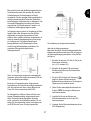
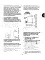
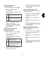
9.2 Control units
The control units should also be mounted on a flat, dry,
vibration-free surface. The mounting height is important.
The units should be positioned so that all users can easily
read the display and operate the buttons.
x Open the cover of the control unit and loosen the
screws on the base.
x Use the housing as a template to make drill-marks for
the fixing-screws.
x At the marked positions, drill three holes (min. 4mm Ø,
3cm long).
x Connect the control unit to the alarm centre (see next
page).
x Connect the control unit to the external components.
x Make any settings necessary in the control unit.
x Mount the control unit housing on the wall. Replace the
front plate containing the control unit PCB and tighten
the fixing screws.

13
UK
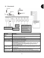
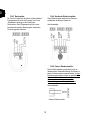
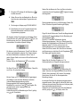
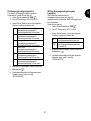
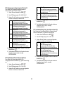
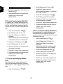
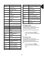
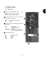
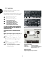
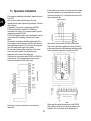
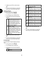
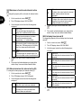
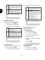
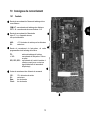
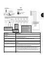
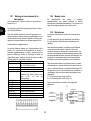
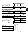
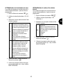
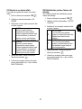
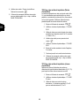
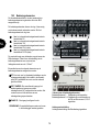
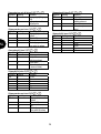
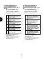
10 Notes on wiring
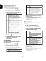
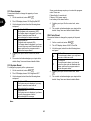
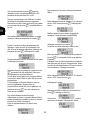
10.1 Alarm centre
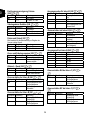
Terminal connector strip for tamper and alarm zones.
COM A/T: Connections for detector tampering
CCT 1…8: Connections for alarm zones 1–8
Terminal connector strip for 12V DC power supply of
external equipment (e.g., detectors)
AUX: +12V permanent voltage for detectors
0V: 0V ground
Terminal connector strip for loudspeaker, progr. outputs and
siren tampering.
TR: Sabotage inputs
+ / LS: Contact for optional 16 Ohm
loudspeaker
OP1, OP2, OP3: Contact for Open Collector Transistor
output (e.g. as trigger signal of dialler)
Terminal strip for control units
12V: 12V+ permanent voltage
0V: 0V ground
Data: Databus
Clock: Databus
N
O
P
M
N
M
O
P

14
UK
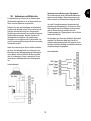
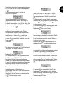
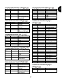
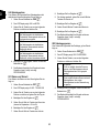
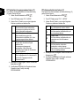
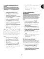
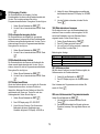
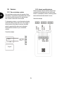
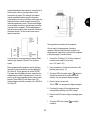
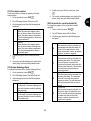
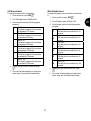
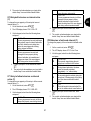
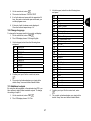
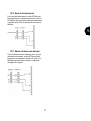
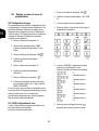
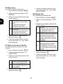
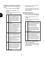
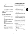
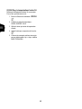
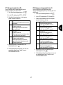
10.2 Control units
The burglar alarm panel can operate with up to four
control units connected via a BUS.
The control units can be connected as a ring or star to
the alarm centre. Connect the control unit as follows:
To next control unit / alarm centre
Terminal connector strip: 0V
To next control unit / alarm centre
Terminal connector strip: 12V
To next control unit / alarm centre
Terminal connector strip: CLK (Clock)
To next control unit / alarm centre
Terminal connector strip: DATA (Data)
The length of the databus must not exceed 200m. For
connecting the control units, use a cable with a wire
diameter of min. 0.6mm.
Other devices that can be connected to the control
units:
ET: A switch for manual ending of exit delay time. The
contact is normally open (NO) and must be closed to
activate.
Ext. Tamper: Additional input on control unit to which
an external tamper contact (NC) can be connected.
The contact must be opened to trigger a tamper
alarm.
PANIC I/P (from panel version 2.04.0151): There
you can connect a panic button.
M
N
O
P
Q
R
S
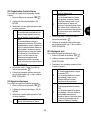
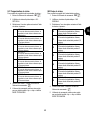
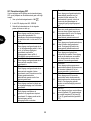
NOTE: The connection cables must be inserted in
the clamps from above
.
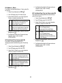
Coding of control units:
Control unit 1: Jumper not connected
Control units 2–4: Jumper connected accordingly to
the pin numbers 2, 3, or 4.
Background lighting:
Background lighting on: Jumper connected.
coding of control units
background lighting
volume beeper
tamper contact
beeper
M
N
O
P
Q
R
S

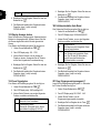
15
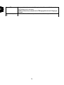
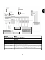
UK
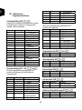
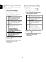
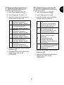
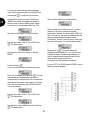
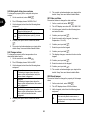
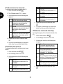
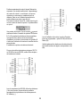
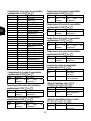
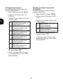
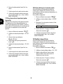
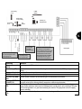
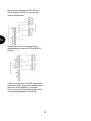
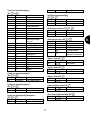
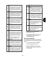
Connection
Meaning
AC mains supply unit (AC IN) Contact for 230V main supply unit
Kick Start jumper (KS) Connect the two contacts of this jumper to start the alarm centre without a 230V mains
power supply.
Battery contact (+ -) Connecting plug from standby power supply
COMMS interface Contact for additional transistor outputs
Reset jumper (NVM RST) Connect the two contacts of this jumper to reset the alarm centre.
Fuses (BAT F-2A / 12VAUX F-
1A)
Always use fuses of the same type. To avoid problems, make sure there is always a good
contact between the fuse holder and the fuse.
Siren sabotage input (TR) For sirens with their own power supply, connect this input direct to the tamper output of the
siren. Otherwise, connect the tamper contact of the siren to the loop between the TR input
and 0V. If no siren is used, connect the TR input direct to the 0V output.
Optional loudspeaker (LS) Connect a 16 Ohm loudspeaker for internal alerts.
Programmable transistor outputs
(OP). Max. power consumption of all
transistor outputs 0.5A.
Siren tamper
it
Optional
loudspeaker
it
12V power supply for
external components (e.g.
Tamper input for external
components (e.g.
A
larm zone 1
–
8 for NC alarm contacts (e.g.
IR sensor). No NO contacts can be
connected. Make sure the alarm zones are
terminated with the corresponding resistors.
Either two different resistors or no resistor
must be used, depending on programming.
If the zone is used, remove the wire jumper.
Control unit
1A AUX fuse for
power supply
2A BAT fuse for
battery charging
A
C
connector of
transformer
Kick
star
Battery
connector
COMMS
interface
NVM
EEPROM
Lid tamper contact

16
UK
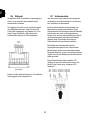
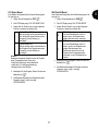
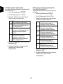
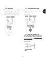
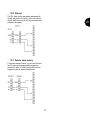
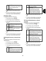
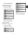
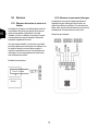
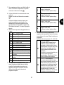
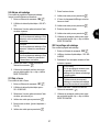
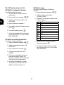
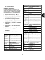
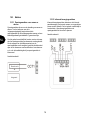
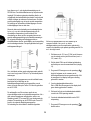
10.3 Detectors
10.3.1 Door and window contacts
Door and window contacts monitor the opening of doors
and windows. To activate the entry/exit delay time, at least
one contact should be mounted on the main entrance
door on which a control unit is also mounted.
For transparency reasons, no more than ten door/window
contacts should be used per alarm zone. If the magnet of
the reed contact of the detector is removed, the switch
contact is opened and the alarm zone is interrupted.
Please read the instructions for your door/window
contacts.
Connection example:
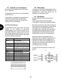
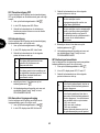
10.3.2 Infrared sensitivity detector
Infrared sensitivity detectors detect the infrared heat
movement of living creatures and must not be used
indoors. For transparency reasons, avoid using motion
sensors with door/window contacts in a zone.
Connection example:
Reed
Ma
g
net

17
UK
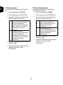
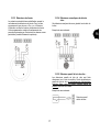
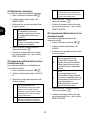
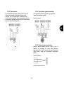
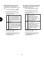
10.3.3 Smoke detector
This burglar alarm panel allows the connection of smoke
detectors. For these, program zone type “fire” or “smoke
detector”, depending on the function of the smoke
detector. This programming result in a special acoustic
warning for persons present (pulsed alarm tone).
10.3.4 Acoustic glass breakage sensor:
These glass breakage sensors evaluate acoustic signals
resulting from glass breakage.
Connection example:
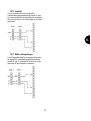
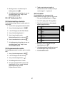
10.3.5 Passive glass breakage sensor:
Passive glass breakage sensors are fixed direct to the
glass pane to be monitored. Only passive glass breakage
sensors can be used that require no line feed but offer a
potential-free alarm contact.
Connection example:
Passive glass breakage
sensor

18
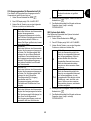
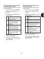
UK
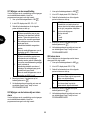
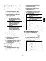
10.4 Outdoor siren and flashlight
To deter burglars and alert the neighbourhood, we
recommend connecting a siren and a flashlight to the
alarm centre.
Note that these alarm devices should be mounted as high
as possible (e.g. at roof height) and the cables should not
be visible. Outdoor acoustic alarms can be a disturbance
to the neighbourhood. Observe country-specific
regulations. We recommend a maximum alarm duration of
three minutes. A visual alarm (flashlight) remains active
until it is acknowledged manually.
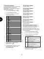
In addition to a siren and flashlight, we recommend
connecting the tamper contact of the combination
signalling device to the tamper input of the alarm centre. If
the siren housing is opened or the connection broken, the
interrupted tamper contact triggers a tamper alarm.
Connection example:
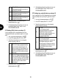
Connecting a signalling device with its own power
supply
The functioning principle of this alarm signalling
combination is based on a permanent power supply of the
siren and a rechargeable battery integrated in the siren
housing.
At a transistor output of the alarm centre, either a bias for
the siren is applied that is removed in the event of an
alarm (or is cut in the event of tampering), or the alarm
centre issues a trigger signal on alarm via the transistor
output that activates the siren and the flashlight.
The alarm duration of the siren is set on the signalling
equipment direct. Here too, the flashlight remains active
until it is acknowledged manually. For correct installation,
please read the installation instructions of the signalling
device with own power supply.
Connection example:
max. 500mA
max. 500mA
Alarm panel
signaling devices

19
UK
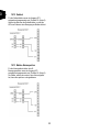
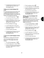
10.5 Dialler
We recommend the use of the additional alarm outputs for
connecting the optional telephone dialling device to the
alarm centre.
You can now connect the outputs with the alarm inputs of
your dialler. Make sure that the polarity of the alarm input
at the dialler is set to -12V (trigger polarity neg.).
Additionally, please read the instructions of your dialler.
Note the information about additional alarm outputs on the
following page.
10.6 Key switch
If programmed accordingly, each zone permits the
connection of a key switch for activating or deactivating
the alarm centre.
You can use key switches with pulse contact or
permanent contact. For key switches with permanent
contact, note that the control units are still active and
misinterpretations can occur if a key switch is still active
but the alarm centre has already been deactivated via the
control unit. We therefore recommend the use of key
switches with pulse contact.
When the key switch is activated, the exit delay time for
the respective area is activated, following which the alarm
centre is activated. In the case of internal areas,
immediate activation is possible. At reactivation, the alarm
centre is deactivated.
Some key switches have additional LED displays that can
be externally activated. If necessary, these can be
connected to the programmed outputs (OP1).

20
UK
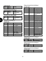
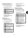
10.7 Fitting and connecting a
loudspeaker
An optional 16Ohm loudspeaker is connected to the
contacts
LS and +.
The loudspeaker can be integrated directly in the housing
of the alarm centre.
Alternatively, the loudspeaker can be mounted as an
additional internal alarm away from the alarm centre. The
distance from the alarm centre should not exceed 20m.
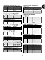
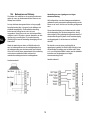
Additional alarm outputs
At the top of the PCB, the alarm centre has contacts for
additional transistor outputs. The cable supplied is
connected to these contacts. The cable pin connection is
described in the following. Note that the colour code of the
cable is not always the same as described below.
Colour
Function
Red (1) +12V permanent
power supply (500mA max.)
Black (2) Ground 0V permanent
Orange/white (3) Not used
Brown/white (4) Fault input of telephone in the case
of line loss (+12V if faulty)
Grey (5) Additional output 8
White (6) Additional output 7
Violet (7) Additional output 6
Blue (8) Additional output 5
Green (9) Additional output 4
Yellow (10) Additional output 3
Orange (11) Additional output 2
Brown (12) Additional output 1
10.8 Relay module
Instead of using the additional transistor outputs, you can
connect an optional relay module with eight changer
relays. Note the information in the relay module.
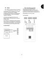
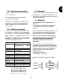
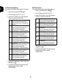
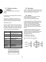
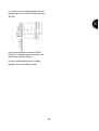
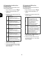
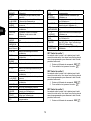
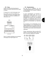
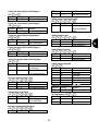
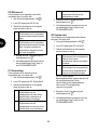
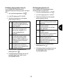
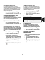
10.9 Resistors
The alarm system can monitor the zones in two ways.
A: Zone closed NC (no resistor inserted)
B: Zone closed 2.2 kOhm (two resistors inserted)
In Variant A, the system can only detect whether the zone
is opened and it always registers an opening as an alarm
in this zone. The tamper contacts of the individual
detectors must be connected separately to the tamper
zone of the alarm centre. The connection examples
described in these instructions refer to Variant A (without
resistors).
In Variant B, the tamper contact and alarm contact are
monitored in one zone. In the event of a change of
resistance, the alarm centre can distinguish whether it is a
case of alarm or tampering. Note that there are two
different resistance values:
A: 2.2 kOhm (red, red, red, gold)
B: 4.7 kOhm (yellow, violet, red, gold)
Note the two variants built in to the detector:
A: B:
2,2
kO
h
A
larm-
contact
4,7kOh
4.7kOh
Sabotage
contact
Sabotage-
contact
2,2
kO
h
A
larm-
contact
Page is loading ...
Page is loading ...
Page is loading ...
Page is loading ...
Page is loading ...
Page is loading ...
Page is loading ...
Page is loading ...
Page is loading ...
Page is loading ...
Page is loading ...
Page is loading ...
Page is loading ...
Page is loading ...
Page is loading ...
Page is loading ...
Page is loading ...
Page is loading ...
Page is loading ...
Page is loading ...
Page is loading ...
Page is loading ...
Page is loading ...
Page is loading ...
Page is loading ...
Page is loading ...
Page is loading ...
Page is loading ...
Page is loading ...
Page is loading ...
Page is loading ...
Page is loading ...
Page is loading ...
Page is loading ...
Page is loading ...
Page is loading ...
Page is loading ...
Page is loading ...
Page is loading ...
Page is loading ...
Page is loading ...
Page is loading ...
Page is loading ...
Page is loading ...
Page is loading ...
Page is loading ...
Page is loading ...
Page is loading ...
Page is loading ...
Page is loading ...
Page is loading ...
Page is loading ...
Page is loading ...
Page is loading ...
Page is loading ...
Page is loading ...
Page is loading ...
Page is loading ...
Page is loading ...
Page is loading ...
Page is loading ...
Page is loading ...
Page is loading ...
Page is loading ...
Page is loading ...
Page is loading ...
Page is loading ...
Page is loading ...
Page is loading ...
Page is loading ...
Page is loading ...
Page is loading ...
Page is loading ...
Page is loading ...
Page is loading ...
Page is loading ...
Page is loading ...
Page is loading ...
Page is loading ...
Page is loading ...
Page is loading ...
Page is loading ...
Page is loading ...
Page is loading ...
Page is loading ...
Page is loading ...
Page is loading ...
Page is loading ...
Page is loading ...
Page is loading ...
Page is loading ...
Page is loading ...
Page is loading ...
Page is loading ...
Page is loading ...
Page is loading ...
Page is loading ...
Page is loading ...
Page is loading ...
Page is loading ...
Page is loading ...
Page is loading ...
Page is loading ...
Page is loading ...
Page is loading ...
Page is loading ...
Page is loading ...
Page is loading ...
Page is loading ...
Page is loading ...
Page is loading ...
Page is loading ...
Page is loading ...
Page is loading ...
Page is loading ...
Page is loading ...
Page is loading ...
Page is loading ...
Page is loading ...
Page is loading ...
Page is loading ...
Page is loading ...
Page is loading ...
Page is loading ...
Page is loading ...
Page is loading ...
Page is loading ...
Page is loading ...
Page is loading ...
Page is loading ...
Page is loading ...
Page is loading ...
Page is loading ...
Page is loading ...
Page is loading ...
Page is loading ...
Page is loading ...
Page is loading ...
Page is loading ...
Page is loading ...
Page is loading ...
Page is loading ...
Page is loading ...
Page is loading ...
Page is loading ...
Page is loading ...
Page is loading ...
Page is loading ...
Page is loading ...
Page is loading ...
Page is loading ...
Page is loading ...
Page is loading ...
Page is loading ...
Page is loading ...
Page is loading ...
Page is loading ...
Page is loading ...
Page is loading ...
Page is loading ...
Page is loading ...
Page is loading ...
Page is loading ...
Page is loading ...
Page is loading ...
Page is loading ...
Page is loading ...
Page is loading ...
Page is loading ...
Page is loading ...
Page is loading ...
Page is loading ...
Page is loading ...
Page is loading ...
Page is loading ...
Page is loading ...
Page is loading ...
Page is loading ...
Page is loading ...
Page is loading ...
Page is loading ...
Page is loading ...
Page is loading ...
Page is loading ...
Page is loading ...
Page is loading ...
Page is loading ...
Page is loading ...
Page is loading ...
Page is loading ...
Page is loading ...
Page is loading ...
Page is loading ...
Page is loading ...
Page is loading ...
Page is loading ...
Page is loading ...
Page is loading ...
-
 1
1
-
 2
2
-
 3
3
-
 4
4
-
 5
5
-
 6
6
-
 7
7
-
 8
8
-
 9
9
-
 10
10
-
 11
11
-
 12
12
-
 13
13
-
 14
14
-
 15
15
-
 16
16
-
 17
17
-
 18
18
-
 19
19
-
 20
20
-
 21
21
-
 22
22
-
 23
23
-
 24
24
-
 25
25
-
 26
26
-
 27
27
-
 28
28
-
 29
29
-
 30
30
-
 31
31
-
 32
32
-
 33
33
-
 34
34
-
 35
35
-
 36
36
-
 37
37
-
 38
38
-
 39
39
-
 40
40
-
 41
41
-
 42
42
-
 43
43
-
 44
44
-
 45
45
-
 46
46
-
 47
47
-
 48
48
-
 49
49
-
 50
50
-
 51
51
-
 52
52
-
 53
53
-
 54
54
-
 55
55
-
 56
56
-
 57
57
-
 58
58
-
 59
59
-
 60
60
-
 61
61
-
 62
62
-
 63
63
-
 64
64
-
 65
65
-
 66
66
-
 67
67
-
 68
68
-
 69
69
-
 70
70
-
 71
71
-
 72
72
-
 73
73
-
 74
74
-
 75
75
-
 76
76
-
 77
77
-
 78
78
-
 79
79
-
 80
80
-
 81
81
-
 82
82
-
 83
83
-
 84
84
-
 85
85
-
 86
86
-
 87
87
-
 88
88
-
 89
89
-
 90
90
-
 91
91
-
 92
92
-
 93
93
-
 94
94
-
 95
95
-
 96
96
-
 97
97
-
 98
98
-
 99
99
-
 100
100
-
 101
101
-
 102
102
-
 103
103
-
 104
104
-
 105
105
-
 106
106
-
 107
107
-
 108
108
-
 109
109
-
 110
110
-
 111
111
-
 112
112
-
 113
113
-
 114
114
-
 115
115
-
 116
116
-
 117
117
-
 118
118
-
 119
119
-
 120
120
-
 121
121
-
 122
122
-
 123
123
-
 124
124
-
 125
125
-
 126
126
-
 127
127
-
 128
128
-
 129
129
-
 130
130
-
 131
131
-
 132
132
-
 133
133
-
 134
134
-
 135
135
-
 136
136
-
 137
137
-
 138
138
-
 139
139
-
 140
140
-
 141
141
-
 142
142
-
 143
143
-
 144
144
-
 145
145
-
 146
146
-
 147
147
-
 148
148
-
 149
149
-
 150
150
-
 151
151
-
 152
152
-
 153
153
-
 154
154
-
 155
155
-
 156
156
-
 157
157
-
 158
158
-
 159
159
-
 160
160
-
 161
161
-
 162
162
-
 163
163
-
 164
164
-
 165
165
-
 166
166
-
 167
167
-
 168
168
-
 169
169
-
 170
170
-
 171
171
-
 172
172
-
 173
173
-
 174
174
-
 175
175
-
 176
176
-
 177
177
-
 178
178
-
 179
179
-
 180
180
-
 181
181
-
 182
182
-
 183
183
-
 184
184
-
 185
185
-
 186
186
-
 187
187
-
 188
188
-
 189
189
-
 190
190
-
 191
191
-
 192
192
-
 193
193
-
 194
194
-
 195
195
-
 196
196
-
 197
197
-
 198
198
-
 199
199
-
 200
200
-
 201
201
-
 202
202
-
 203
203
-
 204
204
-
 205
205
-
 206
206
-
 207
207
-
 208
208
-
 209
209
-
 210
210
-
 211
211
-
 212
212
-
 213
213
-
 214
214
-
 215
215
-
 216
216
-
 217
217
-
 218
218
-
 219
219
-
 220
220
-
 221
221
-
 222
222
-
 223
223
-
 224
224
-
 225
225
-
 226
226
-
 227
227
-
 228
228
-
 229
229
-
 230
230
-
 231
231
-
 232
232
-
 233
233
-
 234
234
-
 235
235
-
 236
236
-
 237
237
-
 238
238
-
 239
239
-
 240
240
-
 241
241
-
 242
242
-
 243
243
-
 244
244
-
 245
245
-
 246
246
-
 247
247
-
 248
248
-
 249
249
-
 250
250
-
 251
251
-
 252
252
-
 253
253
-
 254
254
-
 255
255
-
 256
256
-
 257
257
-
 258
258
-
 259
259
-
 260
260
-
 261
261
-
 262
262
-
 263
263
-
 264
264
-
 265
265
-
 266
266
-
 267
267
-
 268
268
-
 269
269
-
 270
270
-
 271
271
-
 272
272
-
 273
273
-
 274
274
-
 275
275
-
 276
276
-
 277
277
-
 278
278
-
 279
279
-
 280
280
-
 281
281
-
 282
282
-
 283
283
-
 284
284
-
 285
285
-
 286
286
-
 287
287
-
 288
288
-
 289
289
-
 290
290
-
 291
291
-
 292
292
-
 293
293
-
 294
294


Abus AZ4000/05 Installation Instructions Manual
- Category
- Security access control systems
- Type
- Installation Instructions Manual
- This manual is also suitable for
Ask a question and I''ll find the answer in the document
Finding information in a document is now easier with AI
in other languages
- français: Abus AZ4000/05
- Deutsch: Abus AZ4000/05
- Nederlands: Abus AZ4000/05
Related papers
-
Abus 4043158015690 Installation guide
-
Abus 4043158054538 User manual
-
-
Abus 4043158015690 Owner's manual
-
Abus AZ4130 Datasheet
-
-
-
-
Abus BW8040 Specification
-
Other documents
-
Renkforce MAC-608 Owner's manual
-
Cooper Scantronic 9448 User manual
-
Cooper Hand Tools Scantronic 9448 User manual
-
Tyco HS2TCHP E User manual
-
DSC PowerSeries User manual
-
Hama 00104986 Owner's manual
-
-
Trebs MT-066 Datasheet
-
Hager TG550A 2 Installation guide
-
Munters 800EZ Plugin Card Owner's manual