Page is loading ...
Owner's Manual
iCRHFTSMHN'i
Permanently Lubricated
Single Stage
Side Stack
AIR COMPRESSOR
Model No.
919.167461
• Safety Guidelines
• Assembly
• Operation
• Maintenance
• Service and Adjustments
• Troubleshooting
• Repair Parts
CAUTION: Read the Safety Guidelines
and All Instructions Carefully Before
Operating.
Sears, Roebuck and Co., Hoffman Estates, IL 60179 U.S.A.
Visit our Craftsman website: www.sears.com/craftsman
D28071 Revl 7/24/03
hq;_:3! :1EoJ_,_[_o] _hi _h I_-_
WARRANTY ............................................. 2
SPECIFICATION CHART .................................... 3
SAFETY GUIDELINES-DEFINITIONS .......................... 3
IMPORTANT SAFETY INSTRUCTIONS ....................... 3-8
GLOSSARY .............................................. 9
ACCESSORIES .......................................... 9
DUTY CYCLE ............................................ 9
ASSEMBLY ............................................. 1g
INSTALLATION ........................................ f0-11
OPERATION .......................................... f2-14
MAINTENANCE ....................................... f5-16
SERVICE AND ADJUSTMENTS ............................. 17
STORAGE .............................................. 18
TROUBLESHOOTING GUIDE ............................ 19-21
REPAIR PARTS ....................................... 22-25
HOW TO ORDER REPAIR PARTS .................... Back Cover
FULL ONE YEAR WARRANTY AIR COMPRESSOR
If this air compressor fails due to a defect in material or workmanship within
one year from the date of purchase, RETURN IT TO THE NEAREST SEARS
REPAIR CENTER THROUGHOUT THE UNITED STATES AND SEARS WILL
REPAIR IT,FREE OF CHARGE. If purchased from Orchard Supply Hardware,
return to the nearest Orchard Store and Orchard will repair it, free of charge.
If this air compressor is used for commercial or rental purposes, the warranty
will apply for ninety days from the date of purchase.
This warranty gives you specific legal rights and you may have other rights
which vary from state to state.
Sears, Roebuck and Co., Dept. 817WA, Hoffman Estates, IL 60179
D28071 2* ENG

-"1".1=[e]I _1[_:_1 II[o]_I[e] "!':_t.tl
Model No. 919-167461
Max. Developed HP 3
Bore 2.375"
Stroke 1.35"
Voltage-Single Phase 120V
Minimum Branch Circuit Requirement 15 amps
Fuse Type Time Delay
Air Tank Capacity - Gallons 4
Approximate Cut-in Pressure 120
Approximate Cut-out Pressure 150
SCFM@ 40 psig 7.9
SCFM@ 90 psig 5.5
E.'T:I;I_ I_'lrll] Im]=1III_I=_.']-,Im]=1;ll_lil II[o_]_."]
This manual contains information that iS important for you to know and understand. This information
relates to protecting YOUR SAFETY and PREVENTING EQUIPMENT PROBLEMS. To hetp you rec_
ognize this information_ we use the symbols below. Please read the manual and pay attention to these
sec_ions_
_'_lndicates an imminent-
ly hazardous situation
which, if not avoided, will result in
death or serious injury.
_lndicates a potentially
hazardous situation
which, if not avoided, could result in
death or serious injury.
_lndicates a potentially
hazardous situation
which, if not avoided, _ result in
minor or moderate injury.
_"_Used without the
safety alert symbol
indicates a potentially hazardous situ-
ation which, if not avoided, may
result in orooertv damaae.
IhSl_o]-'IL,1+hnlb"Y.'_l_"_'d_[IP,[.._l_o]n/[o _]P,[..+
SAVE THESE INSTRUCTIONS
IMPROPER OPERATION OR MAINTENANCE OF THIS PRODUCT COULD RESULT IN
SERIOUS INJURY AND PROPERTY DAMAGE. READ AND UNDERSTAND ALL WARN-
INGS AND OPERATING INSTRUCTIONS BEFORE USING THIS EQUIPMENT.
Some dust created by power sanding, sawing, grinding, drilling, and other con*
struation activities contains chemicals known (to the State of California) to cause
Cancer, birth defects or other reproductive harm. Some example of these chemicals are:
• lead from lead-based paints
• crystalline silica from bricks and cement and other masonry products
• arsenic and chromium from chemically*treated lumber
Your risk from these exposures varies, depending on how often you do this type of work. To reduce
your exposure to these chemicals: work in a well ventilated area, and work with approved safety
equipment, always wear MSHA/NIOSH approved, propeity fitting face mask or respirator when using
such tools.
When using air tools, basic safety precautions should always be followed to reduce the risk of of per_
sonal injury.
3* ENG D28071
II_ I_o] ;k IP'.'q+IInl[,.'Y.,__1_ &'d__JL_[,._)III,_]LI_+']IIT[_o_+]L_,[,._
Save these instructions
Improper operation or maintenance of this product could result in serious injury and
property damage. Read and understand all warnings and operation instructions before
using this equipment.
,l;1"l'J "-In
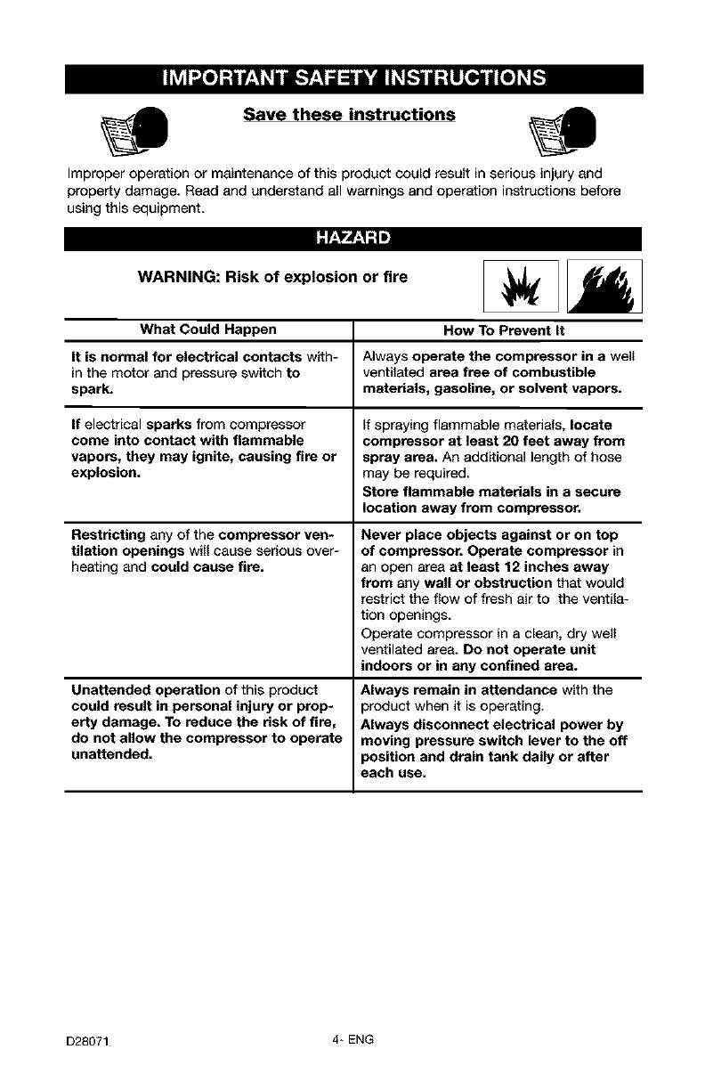
WARNING: Risk of explosion or fire
What Could Happen How To Prevent It
It is normal for electrical contacts with- Always operate the compressor in a well
in the motor and pressure switch to ventilated area free of combustible
spark, materials, gasoline, or solvent vapors.
If electrical sparks from compressor If spraying flammable materials, locate
come into contact with flammable compressor at least 20 feet away from
vapors, they may ignite, causing fire or spray area. An additional length of hose
explosion, may be required
Store flammable materials in a secure
location away from compressor,
Restricting any of the compressor ven-
tilation openings will cause serious over-
heating and could cause fire.
Unattended operation of this product
could result in personal injury or prop-
erty damage. To reduce the risk of fire,
do not allow the compressor to operate
unattended,
Never place objects against or on top
of compressor. Operate compressor in
an open area at least 12 inches away
from any wall or obstruction that would
restrict the flow of fresh air to the ventila-
tion openings.
Operate compressor in a clean, dry well
ventilated area. Do not operate unit
indoors or in any confined area.
Always remain in attendance with the
)roduct when it is operating.
Always disconnect electrical power by
moving pressure switch lever to the off
}osition and drain tank daily or after
each use.
D28071 4* ENG
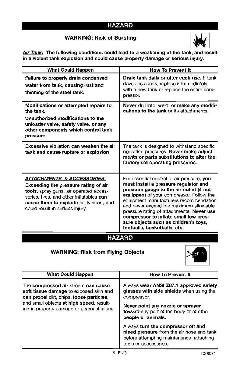
WARNING: Risk of Bursting
Air Tank: The following conditions could lead to a weakening of the tank, and result
in a violent tank explosion and could cause property damage or serious injury.
What Could Happen How To Prevent It
Failure to properly drain condensed Drain tank daily or after each use. If tank
water from tank, causing rust and develops a leak, replace it immediately
thinning of the steel tank. with a new tank or replace the entire com-
pressor.
Modifications or attempted repairs to Never drill into, weld, or make any modifi-
the tank. cations to the tank or its attachments.
Unauthorized modifications to the
unloader valve, safety valve, or any
other components which control tank
pressure.
Excessive vibration can weaken the air The tank is designed to withstand specific
tank and cause rupture or explosion operating pressures. Never make adjust_
merits or parts substitutions to alter the
factory set operating pressures.
ATTACHMENTS & ACCESSORIES:
Exceeding the pressure rating of air
tools, spray guns, air operated acces-
sories, tires, and other inflatables can
cause them to explode or fly apart, and
could result in serious injury.
For essential control of air pressure, you
must install a pressure regulator and
pressure gauge to the air outlet (if not
equipped) of your compressor. Follow the
equipment manufacturers recommendation
and never exceed the maximum allowable
pressure rating of attachments. Never use
compressor to inflate small low pres-
sure objects such as children's toys,
footballs, basketballs, etc.
WARNING: Risk from Flying Objects
What Could Happen How To Prevent It
The compressed air stream can cause
soft tissue damage to exposed skin and
can propel dirt, chips, loose particles,
and small objects at high speed, result-
ing in property damage or personal injury.
Always wear ANSI Z87.1 approved safety
glasses with side shields when using the
compressor.
Never point any nozzle or sprayer
toward any part of the body or at other
people or animals.
Always turn the compressor off and
bleed pressure from the air hose and tank
before attempting maintenance, attaching
tOOlS Or accessories,
5* ENG D28071
:f:I"4..I;I _
WARNING: Risk of Electrical Shock
What Could Happen How To Prevent It
Your air compressor is powered by Never operate the compressor outdoors
electricity. Like any other electrically when it is raining or in wet conditions.
powered device, If it is not used prop- Never operate compressor with protec-
erly it may cause electric shock, tive covers removed or damaged.
Repairs attempted by unqualified per- Any electrical wiring or repairs required
sonnel can result in serious injury or on this product should be performed by
death by electrocution, authorized service center personnel in
accordance with national and local electri-
cal cedes.
Electrical Grounding: Failure to provide Make certain that the electrical circuit to
adequate grounding to this product which the compressor is connected pro-
could result in serious injury or death vides proper electrical grounding, cot-
from electrocution, feet voltage and adequate fuse protec-
See grounding instructions, tion.
/'.,t,_f.,1-!=
WARNING: Risk to Breathing
What Could Happen How To Prevent It
The compressed air directly from your
compressor is not safe for breathing.
The air stream may contain carbon
monoxide, toxic vapors, or solid parti-
cles from the tank. Breathing these
contaminants can cause serious injury
or death.
Sprayed materials such as paint, paint
solvents, paint remover, insecticides,
weed killers, may contain harmful
vapors and poisons.
Air obtained directly from the compressor
should never be used to supply air for
human consumption. In order to use air
produced by this compressor for breath-
ing, suitable filters end in-line safety
equipment must be properly installed.
In-line filters and safety equipment used
in conjunction with the compressor must
be capable of treating air to all applica-
ble local and federal codes prior to
human consumption.
Work in an area with good cress ventila-
tion. Read and follow the safety instruc-
tions provided on the label or safety data
sheets for the materials you are spray-
ing. Use a NtOSH/MSHA approved res-
pirator designed for use with your specific
application.
D28071 6* ENG
WARNING: Risk of Burns
What Could Happen How To Prevent It
Touching exposed metal such as the Never touch any exposed metal parts
compressor head or outlet tubes, can on compressor during or immediately
after operation. Compressor will remain
result in serious burns, hot for several minutes after operation.
Do not reach around protective shrouds
or attempt maintenance until unit has
been allowed to cool.
WARNING: Risk from Moving Parts
What Could Happen How To Prevent It
Moving parts such as the pulley, flywheel, Never operate the compressor with
and belt can cause serious injury if they guards or covers which are damaged or
come into contact with you or your cloth- removed.
ing.
Attempting to operate compressor with Any repairs required on this product
damaged or missing parts or attempting should be performed by authorized
to repair compressor with protective service center personnel.
shrouds removed can expose you to
moving parts and can result in serious
injury.
WARNING: Risk of Failing
What Could Happen
A portable compressor can fall from a
table, workbench, or roof causing dam-
age to the compressor and could
result in serious injury or death to the
operator.
How To Prevent It
Always operate compressor in a stable
secure position to prevent accidental
movement of the unit. Never operate
compressor on a roof or other elevated
position. Use additional sir hose to
reach high locations,
7÷ ENG D28071
WARNING: Risk of Serious Injury or Property Damage When
Transporting Compressor
(Fire, Inhalation, Damage to Vehicle Surfaces)
What Could Happen How To Prevent It
Oil can leak or spill and could result in Always place COMPRESSOR on a pro-
fire or breathing hazard; serious injury or tective mat when transporting to protect
death can result= oil leaks will damage against damage to vehicle from leaks.
carpet, paint or other surfaces in vehi- Remove COMPRESSOR from vehicle
cles or trailers, immediately upon arrival at your destina-
tion.
WARNING: Risk of Unsafe Operation _1=
What Could Happen How To Prevent It
Unsafe operation of your air compressor
could lead to serious injury or death to
you or others.
Review and understand all instructions
and warnings in this m_J_uai.
Become familiar with the operation and
controls of the air compressor.
Keep operating area clear of all persons,
)ets, and obstacles.
Keep children away from the air compres-
sor at ell times.
DO not operate the product when
fatigued or under the influence of eleo-
hol or drugs. Stay alert at all times.
Never defeat the safety features of this
)roduct.
Equip area of operation with a fire extin-
guisher.
DO not operate machine with missing,
broken, or unauthorized parts.
SAVE THESE INSTRUCTIONS
D28071 8* ENG
Become familiar with these terms
before operating the unit.
CFM: Cubic feet per minute.
SCFM: Standard cubic feet per
minute; a unit of measure of air deliv-
ery.
PSIG: Pounds per square inch
gauge; a unit of measure of pressure.
Code Certification: Products that
bear one or more of the following
marks: UL, CUL, ETL, CETL, have
been evaluated by OSHA certified
independent safety laboratories and
meet the applicable Underwriters
Laboratories Standards for Safety.
Cut-In Pressure: While the motor is
off, air tank pressure drops as you
continue to use your accessory.
When the tank pressure drops to a
certain low level the motor will restart
automatically. The low pressure at
which the motor automatically
restarts is called "cut-in" pressure.
Cut-Out Pressure: When an air
compressor is turned on and begins
to run, air pressure in the air tank
begins to build. It builds to a certain
high pressure before the motor auto-
matically shuts off - protecting your
air tank from pressure higher than its
capacity. The high pressure at which
the motor shuts off is called "cut-out"
pressure.
Branch Circuit: Circuit carrying elec-
tricity from electrical panel to outlet.
This unit is capable of powering the following Accessories. The accessories are
available through the current Power and Hand Tool Catalog or full-line Sears
stores.
Accessories • Oil Fog Lubricators
• In Line Filter • Air Hose:l/4", 3/8" or 1/2" I.D. in
• Tire Air Chuck various lengths
• Quick Connector Sets (various Refer to the selection chart located
sizes) on the unit to select the tools this unit
• Air Pressure Regulators is capable of powering.
ml_Tujj_[e,_ q=1
Air compressors should be operated
on not more than a 50% duty cycle.
This means an air compressor that
pumps air more than 50% of one
hour is considered misuse, because
the air compressor is undersized for
the required air demand. Maximum
compressor pumping time per hour is
30 minutes.
9-ENG D28071
Unpacking
1. Remove unit from car_on and
discard all packaging.
HOW TO SET UP YOUR
UNIT
Location of the Air Compressor
Locate the air compressor in a clean,
dry and well ventilated area. The air
compressor should be located at
least 12" away from the wall or other
obstructions that will interfere with
the flow of air. The air compressor
pump and shroud are designed to
allow for proper cooling. The ventila-
tion openings on the compressor are
necessary to maintain proper operat-
ing temperature. Do not place rags or
other containers on or near these
openings.
GROUNDING INSTRUCTIONS
RISK OF ELECTRI-
CAL SHOCK. In
the event of a short circuit, ground-
ing reduces the risk of shock by
providing an escape wire for the
electric current. This air compres-
sor must be properly grounded.
The portable air compressor is
equipped with a cord having a
grounding wire with an appropriate
grounding plug (see following illustra-
tions). The plug must be used with
an outlet that has been installed and
grounded in accordance with all local
codes and ordinances.
1.
The cord set and plug with this
unit contains a grounding pin.
This plug MUST be used with a
grounded outlet.
IMPORTANT: The outlet being used
must be installed and grounded in
accordance with all local codes and
ordinances.
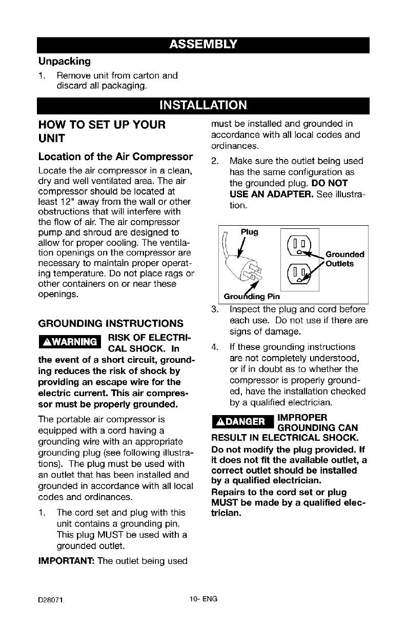
2.
Make sure the outlet being used
has the same configuration as
the grounded plug. DO NOT
USE AN ADAPTER. See illustra-
tion.
_ _luj g _Grounded
_ _Outlets
Grou_g Pin
3. inspect the plug and cord before
each use. Do not use if there are
signs of damage.
4. If these grounding instructions
are not completely understood,
or if in doubt as to whether the
compressor is properly ground-
ed, have the installation checked
by a qualified electrician.
CAN
RESULT IN ELECTRICAL SHOCK.
Do not modify the plug provided. If
it does not fit the available outlet, a
correct outlet should be installed
by a qualified electrician.
Repairs to the cord set or plug
MUST be made by a qualified elec-
trician.
D28071 10-ENG
Extension Cords
Use extra air hose instead of an
extension cord to avoid voltage drop
and power loss to the motor, and to
prevent overheating.
If an extension cord must be used,
be sure it is:
* a 3-wire extension cord that has
a 3-blade grounding plug, and a
3-slot receptacle that will accept
the plug on the product
• in good condition
• no longer than 50 feet
• 12 gauge (AWG) or larger. (Wire
size increases as gauge number
decreases. 10 AWG and 8 AWG
may also be used. DO NOT USE
14 OR 16 AWG.)
Voltage and Circuit Protection
Refer to the Parts Manual for the volt-
age and minimum branch circuit
requirements.
Certain air compressors can be oper-
ated on a 15 amp circuit if the follow-
ing conditions are met.
1. Voltage supply through branch
circuit is 15 amps.
2. Circuit is not used to supply any
other electrical needs (lights,
appliances, etc.).
3. Extension cords comply with
specifications.
4.
Circuit is equipped with a 15
amp circuit breaker or 15 amp
time delay fuse. NOTE: If com-
pressor is connected to a circuit
protected by fuses, use only time
delay fuses. Time delay fuses
should be marked "D" in Canada
and "T" in the US.
If any of the above conditions cannot
be met, or if operation of the com-
pressor repeatedly causes interrup-
tion of the power, it may be neces-
sary to operate it from a 20 amp cir-
cuit. It is not necessary to change the
cord set.
11_ ENG D28071
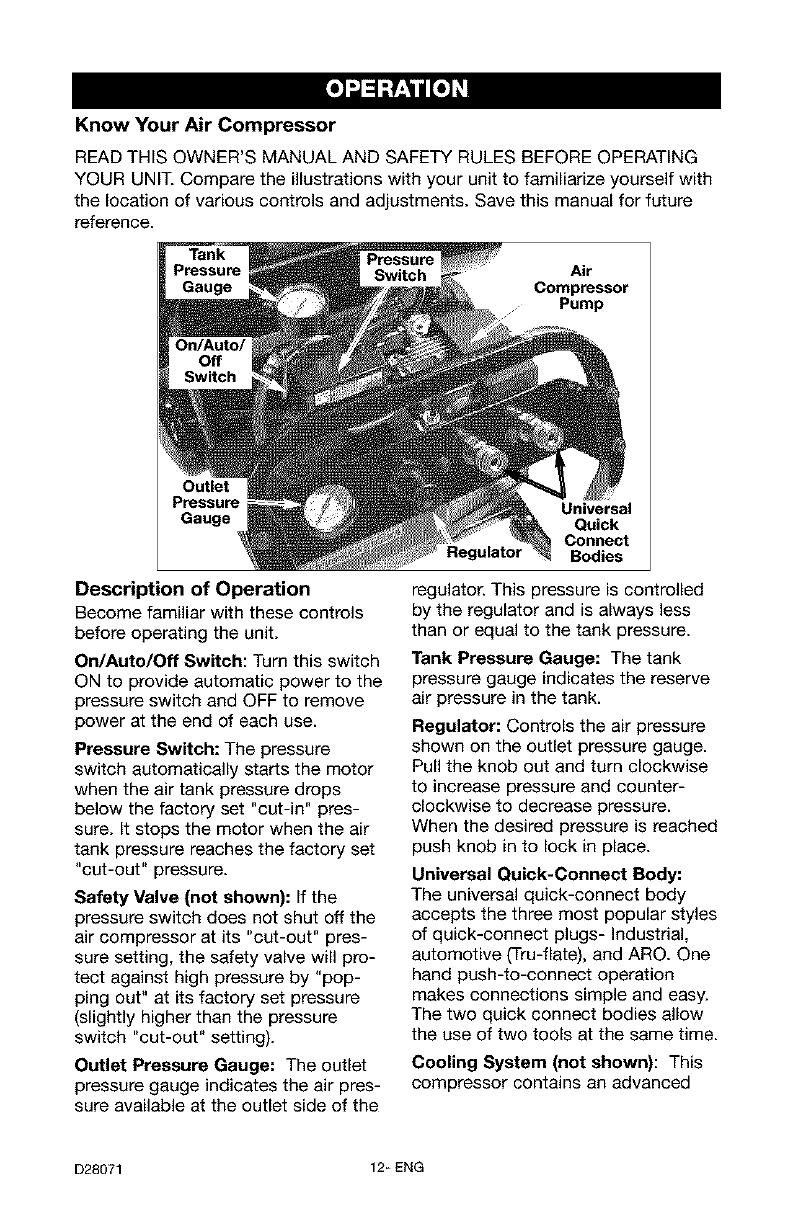
Know Your Air Compressor
READ THIS OWNER'S MANUAL AND SAFETY RULES BEFORE OPERATING
YOUR UNIT. Compare the illustrations with your unit to familiarize yourself with
the location of various controls and adjustments. Save this manual for future
reference.
Air
Compressor
Pump
Outlet
Gauge
Description of Operation
Become familiar with these controls
before operating the unit.
On/Auto/Off Switch: Turn this switch
ON to provide automatic power to the
pressure switch and OFF to remove
power at the end of each use.
Pressure Switch: The pressure
switch automatically starts the motor
when the air tank pressure drops
below the factory set "cut-in" pres-
sure. It stops the motor when the air
tank pressure reaches the factory set
"cut-out" pressure.
Safety Valve (not shown): If the
pressure switch does not shut off the
air compressor at its "cut-out" pres-
sure setting, the safety valve will pro-
tect against high pressure by "pop-
ping out" at its factory set pressure
(slightly higher than the pressure
switch "cut-out" setting).
Outlet Pressure Gauge: The outlet
pressure gauge indicates the air pres-
sure available at the outlet side of the
Universal
Quick
Connect
Regulator Bodies
regulator. This pressure
is controlled
by the regulator and is always less
than or equal to the tank pressure.
Tank Pressure Gauge: The tank
pressure gauge indicates the reserve
air pressure in the tank.
Regulator: Controls the air pressure
shown on the outlet pressure gauge.
Pull the knob out and turn clockwise
to increase pressure and counter-
clockwise to decrease pressure.
When the desired pressure is reached
push knob in to lock in place.
Universal Quick-Connect Body:
The universal quick-connect body
accepts the three most popular styles
of quick-connect plugs- Industrial,
automotive (Tru-flate), and ARO. One
hand push-to-connect operation
makes connections simple and easy.
The two quick connect bodies allow
the use of two tools at the same time.
Cooling System (not shown): This
compressor contains an advanced
D28071 12_ENG
design cooling system. At the heart of
this cooling system is an engineered
fan. It is perfectly normal for this fan
to blow air through the vent holes in
large amounts. You know that the
cooling system is working when air is
being expelled.
Air Compressor Pump:
Compresses air into the air tank.
Working air is not available until the
compressor has raised the air tank
pressure above that required at the
air outlet.
Drain Valve: The drain valve is locat-
ed at the base of the air tank and is
used to drain condensation at the
end of each use.
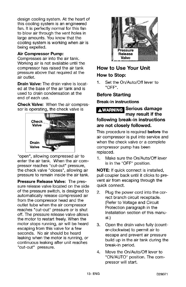
Check Valve: When the air compres-
sor is operating, the check valve is
Check
Valve
Drain
Valve
"open", allowing compressed air to
enter the air tank. When the air com-
pressor reaches "cut-out" pressure,
the check valve "closes", allowing air
pressure to remain inside the air tank.
Pressure Release Valve: The pres-
sure release valve located on the side
of the pressure switch, is designed to
automatically release compressed air
from the compressor head and the
outlet tube when the air compressor
reaches "cut-out" pressure or is shut
off. The pressure release valve allows
the motor to restart freely. When the
motor stops running, air will be heard
escaping from this valve for a few
seconds. No air should be heard
leaking when the motor is running, or
continuous leaking after unit reaches
"cut-out" pressure.
Pressure
Release
Valve
How to Use Your Unit
How to Stop:
1. Set the On/Auto/Off lever to
"OFF".
Before Starting
Break-in instructions
Serious damage
may result if the
following break-in instructions
are not closely followed.
This procedure is required before the
air compressor is put into service and
when the check valve or a complete
compressor pump has been
replaced.
1. Make sure the On/Auto/Off lever
is in the "OFF" position.
NOTE: If quick connect is installed,
pull coupler back until it clicks to pre-
vent air from escaping through the
quick connect.
2. Plug the power cord into the cor-
rect branch circuit receptacle.
(Refer to Voltage and Circuit
Protection paragraph in the
Installation section of this manu-
al.)
3. Open the drain valve fully (count-
er-clockwise) to permit air to
escape and prevent air pressure
build up in the air tank during the
break-in period.
4. Move the On/Auto/Off lever to
"ON/AUTO" position. The com-
pressor will start.
13_ ENG D28071

5. Run the compressor for 15 min-
utes. Make sure the drain valve is
open and there is minimal air
pressure build-up in tank.
6. After 15 minutes, close the drain
valve (clockwise). The air receiver
will fill to "cut-out" pressure and
the motor will stop.
The compressor is now ready for use.
Before Each Start-Up:
1. Place On/Auto/Off lever to
"OFF".
2. Pull regulator knob out, turn
counter-clockwise until it stops.
Push knob in to lock in place.
3. Attach hose and accessories.
NOTE: The hose or accessory
will require a quick connect plug
if the air outlet is equipped with a
quick connect.
Too much air pres-
sure causes a haz-
ardous risk of bursting. Check the
manufacturer's maximum pressure
rating for air tools and accessories.
The regulator outlet pressure must
never exceed the maximum pres-
sure rating.
How to Start:
1. Turn the On/Auto/Off lever to
"AUTO" and allow tank pressure
to build. Motor will stop when
tank pressure reaches "cut-out"
pressure.
2. Pull the regulator knob out and
turn clockwise to increase pres-
sure. When the desired pressure
is reached push knob in to lock
in place. The compressor is
ready for use.
NOTE: Always operate the air com-
pressor in well-ventilated areas free
of gasoline or other combustible
vapors. If the compressor is being
used to operate a sprayer DO NOT
place near the spray area.
D28071 14_ENG
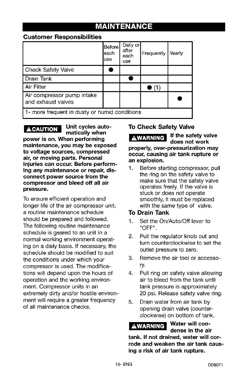
Customer Responsibilities
Check Safety Valve
Drain Tank
Air Filter
Air compressor pump intake
and exhaust valves
Before Daily ol
_ach a_er
each
use use
F_quently
• (1)
1- more frequent in dusty or humid conditions
Yearly
I_ Unit cycles auto-
matically when
power is on. When performing
maintenance, you may be exposed
to voltage sources, compressed
air, or moving parts. Personal
injuries can occur. Before perform-
ing any maintenance or repair, dis-
connect power source from the
compressor and bleed off all air
pressure.
To ensure efficient operation and
longer life of the air compressor unit,
a routine maintenance schedule
should be prepared and followed.
The following routine maintenance
schedule is geared to an unit in a
normal working environment operat-
ing on a daily basis. If necessary, the
schedule should be modified to suit
the conditions under which your
compressor is used. The modifica-
tions will depend upon the hours of
operation and the working environ-
ment. Compressor units in an
extremely dirty and/or hostile environ-
ment will require a greater frequency
of all maintenance checks.
To Check Safety Valve
if the safety valve
does not work
properly, over-pressurization may
occur, causing air tank rupture or
an explosion,
1. Before star_ing compressor, pull
the ring on the safety valve to
make sure that the safety valve
operates freely. If the valve is
stuck or does not operate
smoothly, it must be replaced
with the same type of valve.
To Drain Tank
1. Set the On/Auto/Off lever to
"OFF".
2. Pull the regulator knob out and
turn counterclockwise to set the
outlet pressure to zero.
3. Remove the air tool or accesso-
ry.
4. Pull ring on safety valve allowing
air to bleed from the tank until
tank pressure is approximately
20 psL Release safety valve ring.
5. Drain water from air tank by
opening drain valve (counter-
clockwise) on bottom of tank.
IIR_'I_ Water will con-
dense in the air
tank. If not drained, water will cor-
rode and weaken the air tank caus-
ing a risk of air tank rupture.
15_ENG D28071
6. After the water has been drained,
close the drain valve (clockwise).
The air compressor can now be
stored.
NOTE: If drain valve is plugged,
release all air pressure. The valve
can then be removed, cleaned, the
reinstalled.
Air Filter - Inspection and
Replacement
Hot surfaces. Risk
of burn.
Compressor heads are exposed
when filter cover is removed.
Allow compressor to cool prior to
servicing.
Keep the air filter
clean at all times.
Do not operate the air compressor
with the air filter removed.
A dirty air filter will not allow the com-
pressor pump to operate at full
capacity. Before you use the com-
pressor pump, check the air filter to
be sure it is clean and in place.
If it is dirty, replace it with a new filter.
On some models,the filter may be
removed by using a pair of needle
nose pliers or a screwdriver. Pull or
pry out the old filter and carefully
clean the filter area. Push in the new
air filter.
Air Compressor Pump Intake
and Exhaust Valves
Once a year have a Trained Service
Technician check the air compressor
pump intake and exhaust valves.
MoOr
The motor has an automatic reset
thermal overload protector, if the
motor overheats for any reason, the
overload protector will shut off the
motor. The motor must be allowed to
cool down before restarting. The
compressor will automatically restart
after the motor cools.
if the overload protector shuts the
motor off frequently, check for a pos-
sible voltage problem. Low voltage
can also be suspected when:
1. The motor does not get up to full
power or speed.
2. Fuses blow out when starting
the motor; lights dim and remain
dim when motor is started and is
running.
D28071 16_ ENG
_'V_II Unit cycles auto-
matically when
power is on. When doing
Maintenance, you may be exposed
to voltage sources, compressed air
or moving parts. Personal injuries
can occur. Before performing any
Maintenance or repair, unplug the
compressor and bleed off all air
pressure.
ALL MAINTENANCE AND REPAIR
OPERATIONS NOT LISTED MUST
BE PERFORMED BY TRAINED SER-
VICE TECHNICIAN,
nect electrical supply to the air
compressor.
Bleed tank of pressure.
Allow the air compressor to cool.
To Replace or Clean Check
Valve
1. Release all air pressure from air
tank. See "To Drain Tank" in the
Maintenance section.
2. Unplug unit.
3. Using an adjustable wrench
loosen outlet tube nut at air tank
and pump. Carefully move outlet
tube away from check valve.
4. Using an adjustable wrench
loosen pressure relief tube nut at
air tank and pressure switch.
Carefully move pressure relief
tube away from check valve.
5. Unscrew the check valve (turn
counterclockwise) using a 7/8"
open end wrench. Note the ori-
entation for reassembly.
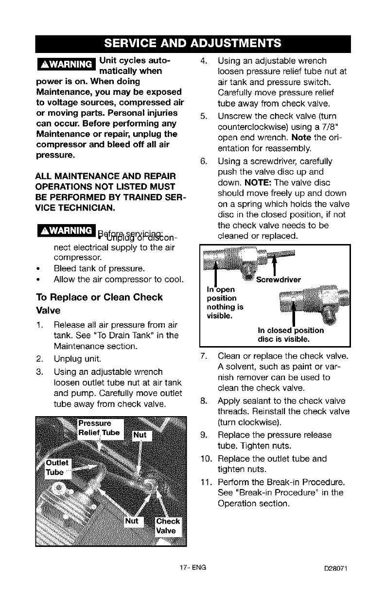
6. Using a screwdriver, carefully
push the valve disc up and
down. NOTE: The valve disc
should move freely up and down
on a spring which holds the valve
disc in the closed position, if not
the check valve needs to be
cleaned or replaced.
open
position
nothing is
visible.
In closed position
disc is visible.
7. Clean or replace the check valve.
A solvent, such as paint or var-
nish remover can be used to
clean the check valve.
8. Apply sealant to the check valve
threads. Reinstall the check valve
(turn clockwise).
9. Replace the pressure release
tube. Tighten nuts.
10. Replace the outlet tube and
tighten nuts.
11. Perform the Break-in Procedure.
See "Break-in Procedure" in the
Operation section.
17_ ENG D28071
Before you store the air compressor,
make sure you do the following:
1. Review the "Maintenance" sec-
tion on the preceding pages and
perform scheduled maintenance
as necessary.
2. Set the On/Auto/Off lever to
"OFF".
3. Turn the regulator counterclock-
wise and set the outlet pressure
to zero.
4. Remove the air tool or accesso-
ry.
5. Pull ring on safety valve allowing
air to bleed from the tank until
tank pressure is approximately
20 psi. Release safety valve ring.
6. Drain water from air tank by
opening drain valve on bottom
of tank.
Water will con-
dense in the air
tank. If not drained, water will cor-
rode and weaken the air tank caus-
ing a risk of air tank rupture.
7. After the water has been drained,
close the drain or drain valve.
NOTE: If drain valve is plugged,
release all air pressure. The valve
can then be removed, cleaned, then
reinstalled.
8. Protect the electrical cord and air
hose from damage (such as
being stepped on or run over).
Wind them loosely around the
compressor handle.
Store the air compressor in a clean
and dry location.
D28071 18_ ENG
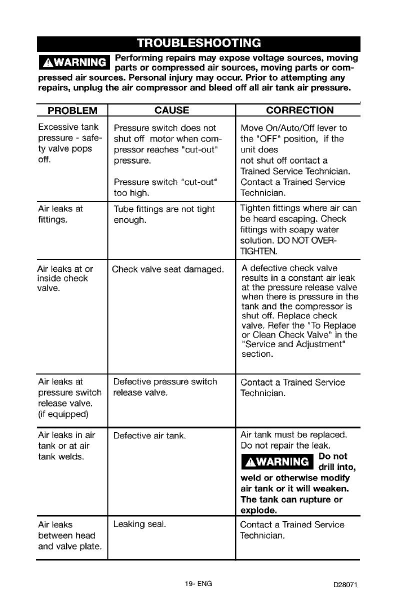
Innl--[oll_'-] _[oIo]nJJP,[_
_ Performing repairs may expose voltage sources, moving
parts or compressed air sources, moving parts or com-
pressed air sources. Personal injury may occur. Prior to attempting any
repairs, unplug the air compressor and bleed off all air tank air pressure.
PROBLEM CAUSE CORRECTION
Excessive tank
pressure - safe-
ty valve pops
off.
Air leaks at
fittings.
Air leaks at or
inside check
valve.
Air leaks at
pressure switch
release valve.
(if equipped)
Air leaks in air
tank or at air
tank welds.
Air leaks
between head
and valve plate.
Pressure switch does not
shut off motor when com-
3ressor reaches "cut-out"
pressure.
Pressure switch "cut-out"
too high.
Tube fittings are not tight
enough.
Check valve seat damaged.
Defective pressure switch
release valve.
Defective air tank.
Leaking seal.
Move On/Auto/Off lever to
the "OFF" position, if the
unit does
not shut off contact a
Trained Service Technician.
Contact a Trained Service
Technician.
Tighten fittings where air can
be heard escaping. Check
fittings with soapy water
solution. DO NOT OVER-
TIGHTEN.
A defective check valve
results in a constant air leak
at the pressure release valve
when there is pressure in the
tank and the compressor is
shut off. Replace check
valve. Refer the "To Replace
or Clean Check Valve" in the
"Service and Adjustment"
section.
Contact a Trained Service
Technician.
Air tank must be replaced.
Do not repair the leak.
Do not
drill into,
weld or otherwise modify
air tank or it will weaken.
The tank can rupture or
explode.
Contact a Trained Service
Technician.
19_ ENG D28071
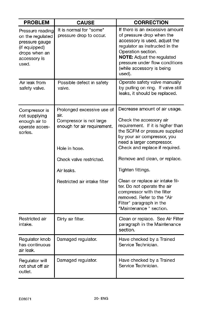
PROBLEM CORRECTION
Pressure reading
on the regulated
pressure gauge
(if equipped)
drops when an
accessory is
used.
CAUSE
It is normal for "some"
pressure drop to occur.
If there is an excessive amount
of pressure drop when the
accessory is used, adjust the
regulator as instructed in the
Operation section.
NOTE: Adjust the regulated
pressure under flow conditions
(while accessory is being
used).
Air leak from Possible defect in safety Operate safety valve manually
safety valve, valve, by pulling on ring. If valve still
leaks, it should be replaced.
Decrease amount of air usage.
Prolonged excessive use of
air.
Compressor is not large
enough for air requirement.
Hole in hose.
Check valve restricted.
Air leaks.
Restricted air intake filter
Compressor is
not supplying
enough air to
operate acces-
sories.
Check the accessory air
requirement. If it is higher than
the SCFM or pressure supplied
by your air compressor, you
need a larger compressor.
Check and replace if required.
Remove and clean, or replace.
Tighten fittings.
Clean or replace air intake fil-
ter. Do not operate the air
compressor with the filter
removed. Refer to the "Air
Filter" paragraph in the
"Maintenance " section.
Restricted air Dirty air filter. Clean or replace. See Air Filter
intake, paragraph in the Maintenance
section.
Regulator knob Damaged regulator. Have checked by a Trained
has continuous Service Technician.
air leak.
Regulator will Damaged regulator. Have checked by a Trained
not shut off air Service Technician.
outlet.
D28071 20-ENG
/