Campbell Hausfeld CHN70500 User manual
- Category
- Power tools
- Type
- User manual
This manual is also suitable for

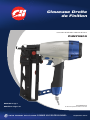
Straight Finish Nailer
FRANÇAISE: Page 21
ESPAÑOL: Página 41
MAKES IT EASY TO DO IT LIKE A PRO chpower.com
Operating Instructions and Parts Manual
CHN70500
IN729900AV 6/10
© 2010 Campbell Hausfeld/Scott Fetzer

Description . . . . . . . . . . . . . . . . . . . . . . . . . 3
Specifications . . . . . . . . . . . . . . . . . . . . . . . 3
Safety Guidelines. . . . . . . . . . . . . . . . . . . . 4
Safety Symbols . . . . . . . . . . . . . . . . . . . . . . 4
Important Safety Information . . . . . . . . 4
Instructions Pertaining to a Risk
of Fire, Electric Shock, or Injury
to Persons. . . . . . . . . . . . . . . . . . . . . . . . . 4
California Proposition 65 . . . . . . . . . . . 4
General . . . . . . . . . . . . . . . . . . . . . . . . . . . 4
Work Area. . . . . . . . . . . . . . . . . . . . . . . . . 4
Personal Safety . . . . . . . . . . . . . . . . . . . . 5
Electrical Safety. . . . . . . . . . . . . . . . . . . . 5
Tool Use and Care . . . . . . . . . . . . . . . . . 5
Service. . . . . . . . . . . . . . . . . . . . . . . . . . . . 7
Air Source. . . . . . . . . . . . . . . . . . . . . . . . . 7
Unpacking. . . . . . . . . . . . . . . . . . . . . . . . . . 7
Contents. . . . . . . . . . . . . . . . . . . . . . . . . . 7
Additional Items Not Included . . . . . . 7
Assembly . . . . . . . . . . . . . . . . . . . . . . . . . . . 7
Glossary . . . . . . . . . . . . . . . . . . . . . . . . . . . . 8
Getting To Know Your
Angle Finish Nailer Like A Pro . . . . . . . . 9
Features . . . . . . . . . . . . . . . . . . . . . . . . . . . . 9
Anti-Dry Fire . . . . . . . . . . . . . . . . . . . . . . 9
Tethered No-mar / Stud Finder Tip . . 9
Low Nail Indicator Lights. . . . . . . . . . . 9
Nail Placement Laser Pointer . . . . . . . 9
Bubble Level . . . . . . . . . . . . . . . . . . . . . . 9
Set-Up . . . . . . . . . . . . . . . . . . . . . . . . . . . . 10
Lubrication . . . . . . . . . . . . . . . . . . . . . . 10
Minimum Components Required
for Hook-up. . . . . . . . . . . . . . . . . . . . . . 10
Hook-up Instructions For Nailer
to Air Supply . . . . . . . . . . . . . . . . . . . . . 10
Air Hose Requirements. . . . . . . . . . . . 10
Loading / Unloading The Nailer . . . . 11
Loading the Nailer . . . . . . . . . . . . . . 11
Unloading the Nailer . . . . . . . . . . . . 11
Adjusting the Nail Penetration . . . . . 11
Adjusting the Direction
of the Exhaust . . . . . . . . . . . . . . . . . . . . 11
Installing and Removing
No-Mar Tip . . . . . . . . . . . . . . . . . . . . . . 11
Pre-Operation. . . . . . . . . . . . . . . . . . . . . . 12
Operational Modes . . . . . . . . . . . . . . . 12
Sequential Mode. . . . . . . . . . . . . . . . 12
Bump Mode . . . . . . . . . . . . . . . . . . . . 12
Safety Lockout Mode . . . . . . . . . . . . 12
Work Contact Element (WCE). . . . . . 12
Electronics ON / OFF Switch . . . . . . . 13
Operation . . . . . . . . . . . . . . . . . . . . . . . . . 14
Nail Placement Laser Pointer . . . . . . 14
Firing the Nailer . . . . . . . . . . . . . . . . . . 14
Low Nail Indicator Lights. . . . . . . . . . 14
Bubble Level . . . . . . . . . . . . . . . . . . . . . 14
Stud Finder . . . . . . . . . . . . . . . . . . . . . . 15
Storage . . . . . . . . . . . . . . . . . . . . . . . . . . . . 15
Maintenance. . . . . . . . . . . . . . . . . . . . . . . 15
Clearing a Jam from the Nailer . . . . . 15
Nailer Repair . . . . . . . . . . . . . . . . . . . . . 15
Replacement Parts. . . . . . . . . . . . . . . . 16
Battery Replacement. . . . . . . . . . . . . . 16
Assembly Procedure for Seals . . . . . . 16
Technical Service . . . . . . . . . . . . . . . . . 16
Fastener Interchange Information. . 16
Fasteners . . . . . . . . . . . . . . . . . . . . . . . . 16
Troubleshooting Guide . . . . . . . . . . . . . 17
Replacement Parts List
for Angle Finish Nailer . . . . . . . . . . 18 - 19
Warranty . . . . . . . . . . . . . . . . . . . . . . . . . . 20
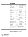
Table of Contents
For parts, product and service information
Visit: www.chpower.com
Call : Customer Service at 1-800-543-6400
Address any correspondence to: Campbell Hausfeld
Attn: Customer Service
100 Production Drive
Harrison, OH 45030 U.S.A.

Operating Instructions and Parts Manual
Straight Finish Nailer
www.chpower.com
3
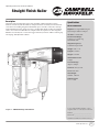
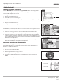
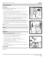
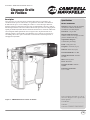
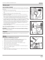
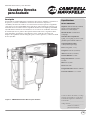
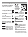
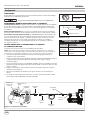
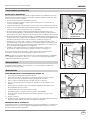
Description
This nailer is designed for decorative trim, molding, window and door casings,
furniture trim, door jamb installation, and picture frame assembly. Features include:
convenient rear loading magazine which holds up to 110 nails, tethered no-mar tip
with stud finder function, quick clear nose, an adjustable depth of drive mechanism,
oil free, electronic low nail indicator, nail placement laser pointer, in-line magazine,
bubble level, anti-dry fire, conversion trigger with safety lockout, rubber comfort grip,
swivel plug, and adjustable exhaust.
Figure 1 - CHN70500 Angle Finish Nailer
Specifications
Model CHN70500
Requires: 0.7 Avg SCFM using 10
fasteners per minute at 90 psi
Air Inlet: 1/4 inch NPT
Fastener Size Range:
1 inch to 2-1/2 inch 16g
brad finish nails
Magazine Capacity:
110 fasteners per load
Weight: 5 lbs., 5 oz.
Length: 13 inches
Height: 12 inches
Maximum Pressure:
120 psi
Pressure Range:
70 psi to 120 psi
Batteries: Two (2) AAA
Laser: Class IIIA
Wavelength:
640 nm - 660 nm
Radiant Power:
1.53 < 5 mW
Locate model number and date code on
magazine and / or tool body. Record below:
Model #: _____________________________
Date Code: ___________________________
Retain these numbers for future reference.

4
Safety Guidelines
This manual contains
information that is very
important to know and
understand. This information
is provided for SAFETY and
to PREVENT EQUIPMENT
PROBLEMS. To help recognize
this information, observe the
following symbols.
Danger
indicates an
imminently hazardous situation
which, if not avoided, WILL result
in death or serious injury.
Warning
indicates a
potentially hazardous situation
which, if not avoided, COULD
result in death or serious injury.
Caution
indicates a
potentially hazardous situation
which, if not avoided, MAY result in
minor or moderate injury.
Notice
indicates
important information, that if not
followed, may cause damage to
equipment.
NOTE: Information that
requires special attention.
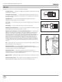
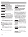
Safety Symbols
The following Safety Symbols
appear throughout this manual
to alert you to important safety
hazards and precautions.
Important Safety Information
INSTRUCTIONS PERTAINING TO A RISK OF FIRE, ELECTRIC SHOCK, OR
INJURY TO PERSONS
This manual contains important safety, operational and maintenance information. If
you have any questions, please call 1-800-543-6400 for customer assistance.
When using tools, basic precautions should always be followed,
including the following:
CALIFORNIA PROPOSITION 65
This product or its power cord may contain chemicals known to the State
of California to cause cancer and birth defects or other reproductive
harm. Wash hands after handling.
You can create dust when you cut, sand, drill or grind
materials such as wood, paint, metal, concrete, cement, or
other masonry. This dust often contains chemicals known to cause cancer, birth
defects, or other reproductive harm. Wear protective gear.
GENERAL
a. To reduce the risks of electric shock, fire, and injury to persons, read
all the instructions before using the tool. Failure to follow warnings,
dangers, and cautions could result in DEATH or SERIOUS INJURY.
b. Be thoroughly familiar with the controls and the proper use of the
equipment. Follow all instructions. Contact your Campbell Hausfeld representative
if you have any questions.
c. Only persons well acquainted with these rules of safe operation should be allowed
to use the unit.
Do not operate or allow anyone else to operate the nailer if any warnings
or warning labels are not legible. Warnings or warning labels are located
on the nailer magazine and body.
Always assume the nailer contains nails. Respect the tool as a working
implement; no horseplay. Always keep others at a safe distance from
the work area in case of accidental discharge of nails. Do not point the tool toward yourself or
anyone whether it contains fasteners or not. Accidental triggering of the nailer could result in
death or serious personal injury.
Do not make any modifications to the tool without first obtaining
written approval from Campbell Hausfeld. Do not use the nailer if any
shields or guards are removed or altered. Do not use the nailer as a hammer. Personal injury or
tool damage may occur.
Clean and check all air supply hoses and fittings before connecting the
nailer to an air supply. Replace any damaged or worn hoses or fittings.
Tool performance or durability may be reduced.
WORK AREA
a. Keep the work area clean and well lighted. Cluttered benches and dark areas
increase the risks of electric shock, fire, and injury to persons.
b. Do not operate the tool in explosive atmospheres, such as in the
presence of flammable liquids, gases, or dust. The tool is able to create
sparks resulting in the ignition of the dust or fumes.
c. Keep bystanders, children, and visitors away while operating the tool.
Distractions are able to result in the loss of control of the tool.
Operating Instructions and Parts Manual
www.chpower.com
Risk of
Personal
Injury
Risk of Fire
Wear Eye
and Mask
Protection
Read Manual
First
Risk of
Explosion
Risk of Falling Wear Eye
Protection
Wear Hearing
Protection
Risk of Shock
CHN70500

5
This is a
Class IIIA
Laser Product that laser
radiation
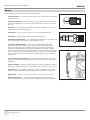
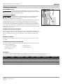
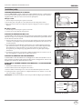
h. Never look directly into
the laser beam or its
direct reflection. Lasers
are harmful to the eyes.
i. Do not set up the tool
at eye level or operate
the tool on or near a
reflective surface. The
laser beam could be
projected into your own or
someone else’s eyes.
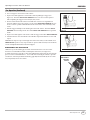
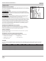
Never place hands or any other
body parts in the nail discharge area
of the nailer. The nailer might eject a fastener and could
result in death or serious personal injury.
ELECTRICAL SAFETY
Replace batteries only with same
size batteries. Do not mix old and
new batteries. Using wrong size batteries can create a risk
of fire or injury.
The front end of the tool may be
made “live” if the tool comes
into contact with live wiring in the wall. TO PREVENT
ACCIDENTAL ELECTRICAL SHOCK, HOLD TOOL ONLY BY
THE SOFT GRIP HANDLE.
TOOL USE AND CARE
a. Do not force the tool. Use the correct tool for the application.
The correct tool will do the job better and safer at the rate for
which the tool is designed.
Disconnect the tool from the air source before
making adjustments, doing tool maintenance,
clearing jams, touching the safety yoke, leaving work area, loading,
or unloading the tool. Such precautionary measures reduce the risk of
injury to persons.
b. Store the tool when it is idle out of reach of children and
other untrained persons. A tool is dangerous in the hands of
untrained users.
c. Maintain the tool with care. A properly maintained tool
reduces the risk of problems and is easier to control.
d. Use only those fasteners listed in the “Fastener Interchange
Information” section on page 16 of this manual. Fasteners
not identified for use with this tool by the tool manufacturer
are able to result in a risk of injury to persons or tool damage
when used in this tool.
PERSONAL SAFETY
a. Stay alert. Watch what you are doing and use common
sense when operating the tool. Do not use the tool
while tired or under the influence of drugs, alcohol, or
medication. A moment of inattention while operating the
tool increases the risk of injury to persons.
b. Dress properly. Do not wear loose clothing or jewelry.
Contain long hair. Keep hair, clothing, and gloves away
from moving parts. Loose clothes, jewelry, or long hair
increases the risk of injury to persons as a result of being
caught in moving parts.
c. Do not overreach. Keep proper footing and
balance at all times. Proper footing and balance
enables better control of the tool in unexpected
situations.
d. Use safety equipment. A dust mask, non-skid safety shoes
and a hard hat must be used for the applicable conditions.
Ensuring that the tool is used
only when the operator and all
other personnel in the work area are wearing ANSI Z87
eye protection equipment, and when required, other
appropriate protection equipment such as head, hearing
and foot protection equipment. Serious eye or permanent hearing
loss could result.
e. Always wear hearing protection when using the
tool. Prolonged exposure to high intensity noise
is able to cause hearing loss.
f. Do not attach the hose or tool to your body.
Attach the hose to the structure to reduce the risk of loss of
balance if the hose shifts.
g. Always assume that the tool contains fasteners.
Do not point the tool toward yourself or anyone
whether it contains fasteners or not.
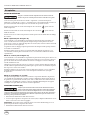
Do not drop or throw the tool. Dropping
or throwing the tool can result in damage that
will make the tool unusable or unsafe. If the tool has been dropped
or thrown, examine the tool closely for bent, cracked or broken parts
and air leaks. STOP and repair before using or serious injury could
occur.
Avoid long extended periods of work with the
nailer. Stop using the nailer if you feel pain in
hands or arms.
Hold tool by insulated gripping surface when
performing an operation where the tool or
fastener may contact hidden wiring. Contacting a “live” wire will
make exposed metal parts of the tool “live” and shock the operator.
CHN70500
www.chpower.com
Important Safety Information (Continued)
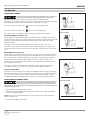
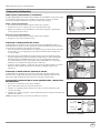
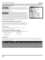
Figure 2
Operating Instructions and Parts Manual

6
Operating Instructions and Parts Manual
www.chpower.com
Important Safety Information (Continued)
e. Always work in a well-ventilated area. Wear OSHA-
approved dust mask.
Always disconnect the tool from the power
source when unattended, performing any
maintenance or repair, clearing a jam, loading, unloading , or
moving the tool to a new location.
Always fit tool with a fitting or hose coupling
on or near the tool in such a manner that all
compressed air in the tool is discharged at the time the fitting or
hose coupling is disconnected. Do not use a check valve or any other
fitting which allows air to remain in the nailer. Death or serious
personal injury could occur.
Never carry the nailer by the air hose or pull
the hose to move the nailer or a compressor.
Keep hoses away from heat, oil and sharp edges. Replace any hose
that is damaged, weak or worn. Personal injury or tool damage
could occur.
Do not drive a nail on top of other nails. The
nail could glance and cause death or a serious
puncture wound.
Do not use tool if laser guide power switch does
not turn it on or off. Any tool that cannot be
controlled with the switch is dangerous and must be repaired.
f. Ensure the laser guide power switch is in the off position
before inserting batteries. Inserting the batteries into the
tool with the switch on invites accidents.
g. Turn laser guide Off before making any adjustments,
changing accessories, or storing. Such preventive safety
measures reduce the risk of accidents.
When batteries are not in use, keep them away
from metal objects such as paper clips, coins,
keys, nails, or screws that can make a connection from one terminal
to another. Shorting the battery terminals together may cause sparks,
burns, a fire, or damage to the batteries.
h. This tool must NOT be modified or used for any
application other than that for which it was designed.
i. Under abusive conditions, liquid may be ejected from the
batteries. Avoid contact. If contact accidentally occurs,
flush with water. If liquid contacts eyes, seek medical help.
Liquid ejected from the batteries may cause irritation or
burns.
Use of controls or adjustments or performance
of procedures other than those specified herein
may result in hazardous radiation exposure.
j. The use of optical instruments with this product will
increase eye hazard.
k. Turn off laser beam when it is not in use or when tool will
be left unattended.
l. Do not remove any labels from the tool.
m. The product will emit a laser beam from the aperture.
The users of the product shall be limited to professional
operators. In normal operation and maintenance
conditions, the operators shall wear protective eyewear to
prevent injury to the eyes.
Do not expose tool to extreme heat.
n. Do not store in locations where the temperature may
reach or exceed 120°F (49°C), such as a metal tool shed, or
a car in the summer. This can lead to deterioration of the
battery.
o. Do not disassemble tool.
p. Remove batteries when storing tool for an extended time.
NOTE: Battery temperature will increase during and shortly
after use.
Only use new Alkaline replacement batteries [two (2) AAA
required]. Do not mix old and new batteries.
Battery shelf life - the included batteries may be in a slightly
depleted state or dead depending on how long the product has
awaited purchase. Do not return product to store for depleted
batteries; please call Campbell Hausfeld at 1-800-543-6400 for
assistance.
q. Do not modify or alter the nailer or any nailer parts. Do
not use the nailer if any shields or guards are removed or
altered. Do not use the nailer as a hammer. Personal injury
or tool damage may occur.
Do not use any type of flammable gases or
oxygen as a power source for the nailer.
Use filtered, lubricated, regulated compressed air only. Use of a
compressed gas instead of compressed air may cause the nailer to
explode which will cause death or serious personal injury.
Never use gasoline or other flammable liquids
to clean the nailer. Never use the nailer in
the presence of flammable liquids or gases. Vapors could ignite by a
spark and cause an explosion which will result in death or serious
personal injury.
r. Avoid using the nailer when the magazine is empty.
Accelerated wear on the nailer may occur.
Do not modify or disable the Work Contact
Element (WCE). Do not tie or tape the WCE
or trigger in a depressed position. Death or serious personal injury
could result.
Always check that the Work Contact Element
(WCE) is operating properly. A nail could
accidentally be driven if the WCE is not working properly. Personal
injury may occur.
Do not touch the trigger unless driving nails.
Never attach air line to nailer or carry nailer
while touching the trigger. The tool could eject a fastener which will
result in death or serious personal injury.
CHN70500

7
Important Safety Information (Continued)
SERVICE
a. Tool service must be performed only by qualified repair
personnel.
b. When servicing a tool, use only identical replacement
parts. Use only authorized parts.
c. Use only the lubricants supplied with the tool or specified
by the manufacturer.
Disconnect air supply and release tension
from the pusher before attempting to clear
jams because fasteners can be ejected from the front of the nailer.
Personal injury may occur.
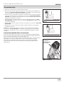
AIR SOURCE
a. Never connect to an air source that is capable of exceeding
200 psi. Over pressurizing the tool is able to result in
bursting, abnormal operation, breakage of the tool or
serious injury to persons. Use only clean, dry, regulated
compressed air at the rated pressure or within the rated
pressure range as marked on the tool. Always verify prior to
using the tool that the air source has been adjusted to the
rated air pressure or within the rated air-pressure range.
b. Never use oxygen, carbon dioxide, combustible gases or
any bottled gas as an air source for the tool. Such gases are
capable of explosion and serious injury to persons.
Air compressors providing air to the nailer
should follow the requirements established
by the American National Standards Institute Standard B19.3-1991;
Safety Standard for Compressors for Process Industries. Contact your
air compressor manufacturer for information.
SAVE THESE INSTRUCTIONS
DO NOT DISCARD
www.chpower.com
Unpacking
After unpacking the unit, inspect carefully for any damage that
may have occurred during transit. Check for loose, missing
or damaged parts. Make sure to tighten fittings, bolts, etc.,
before putting unit into service. Check to be sure all supplied
accessories are enclosed with the unit. In case of questions,
damaged or missing parts, please call 1-800-543-6400 for
customer assistance.
CONTENTS
u Finish Nailer
u 2-1/2 inch 16 g Brad Finish Nails
u Batteries
u Wrenches
u Operating Instructions
u Warranty Card
u Carry Bag
ADDITIONAL ITEMS NOT INCLUDED
u Compressor (must be able to maintain a minimum of 70 psi
when the nailer is being used)
u Air hose
u Small tool for clearing jams
u Threadlock glue
u ANSI Z87 eye protection
u Hearing protection and other personal protective
equipment as required
Assembly
This tool comes fully assembled.
The DANGER, WARNING, CAUTION, and NOTICE
notifications and instructions in this manual cannot
cover all possible conditions and situations that may
occur. It must be understood by the operator that
common sense and caution are factors which cannot
be built into this product, but must be supplied by the
operator.
CHN70500
Operating Instructions and Parts Manual

Operating Instructions and Parts Manual
8
Glossary
Become familiar with these terms before operating the unit.
ACTUATE (TOOL) — To cause movement to the tool’s component(s) intended to
drive the fastener.
ACTUATION SYSTEM — The use of a trigger, work contact element (WCE) and/
or other operating control, separately or in combination or sequence, to actuate
the tool.
AIR INLET — The opening in which the compressed air supply is connected,
usually by means of a threaded fitting.
FASTENERS — This tool uses 1 inch to 2-1/2 inch 16g brad finish nails.
MAGAZINE — The part of the nailer that holds the Fasteners.
MAXIMUM AIR PRESSURE — The maximum allowable pressure of compressed
air, as specified by the manufacture, for operating the tool.
NO-MAR / STUD FINDER TIP — The no-mar / stud finder tip is designed
to eliminate marks caused by the wire-form Work Contact Element (WCE).
The no-mar tip may be removed and tethered to the tool if not required (See
INSTALLING AND REMOVING NO-MAR / Stud finder TIP) or when a slightly
deeper countersink is preferred. Simply slide the no-mar off the WCE and attach
to the storage post on the magazine. The tip also functions as a convenient stud
finder. To utilize the no-mar / stud finder tip, simply slide it over the tools WCE
(see Figure 5).
psi (POUNDS PER SQUARE INCH) —Measurement of the pressure exerted by
the force of the air. The actual psi output is measured by a pressure gauge on the
compressor.
QUICK COUPLER — A quick coupler is designed to work in combination with a
quick plug to quickly and easily join a pneumatic tool to an air hose (see Figure 3).
QUICK PLUG — A quick plug is designed to work in combination with a quick
coupler to quickly and easily join a pneumatic tool to an air hose (see Figure 4).
REGULATOR — A device used to control air pressure to an air operated tool
THREAD LOCK GLUE — A locking glue that is applied to the screw threads
before installing. Prevents the screws from working loose during tool operation.
Figure 3 - Quick Coupler
Figure 4 - Quick Plug
Figure 5 - No-mar / Stud finder Tip
www.chpower.com
CHN70500

9
Features
ANTI-DRY FIRE
This tool is equipped with an Anti-Dry
Fire feature. This prevents the Work
Contact Element (WCE) from being
pushed in when only a few nails remain.
Simply load new nail clip behind
remaining nails to continue shooting.
TETHERED NO-MAR /
STUD FINDER TIP
The tool is fitted with a no-mar tip which
also acts as a convenient stud finder. To
utilize the no-mar tip, simply slide it over
the tools WCE.
LOW NAIL INDICATOR LIGHTS
The tool is equipped with lights on either
side of the tool near the nose. When the
nail count becomes low, the lights will
turn yellow. When the nail count is nearly
out, the Anti-Dry Fire feature will engage
and the lights will turn red. (See Loading
the Nailer section).
NAIL PLACEMENT LASER POINTER
The tool is equipped with a laser mounted
near the nose. This can be seen through
the wide slots in the WCE and / or no-
mar tip. The laser will indicate exact
placement of the fastener.
This is a Class IIIA
Laser Product that
emits laser radiation. Do not stare into beam
or view directly with optical instruments.
BUBBLE LEVEL
The tool is equipped with a bubble level
located on the head cap. This will assist
in aligning the tool for level driving of the
fastener. The bubble level will assist in
vertical and horizontal positioning of the
tool.
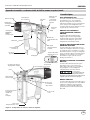
Getting To Know Your Straight Finish Nailer Like A Pro
www.chpower.com
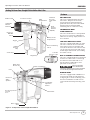
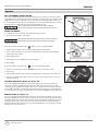
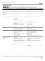
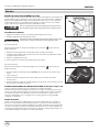
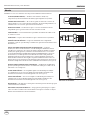
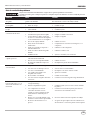
Figure 6 - Components of the Straight Finish Nailer
CHN70500
Operating Instructions and Parts Manual
Pull-out Warning
Decal
Tethered
No-mar /
Stud finder
Tip
Adjustable
Exhaust
Deflecter
Bubble Level
Trigger
Rubber
Comfort
Grip
Work
Contact
Element
(WCE)
Battery Cover/
Compartment
Conversion Switch
Swivel Plug
ADC
Thumbwheel
Electronics
ON / OFF
Switch
Magazine
Stud Finder Light
Low Nail
Indicator Light
Stud Finder
Operation
Button
Pusher Latch Button
Quick Clear
Nose Cover
Electronics
Audio
Speaker
Laser
Nail Pusher
No-mar tip
Storage
Post
Nail Loading
Area
See Below

Operating Instructions and Parts Manual
10
CHN70500
www.chpower.com
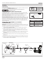
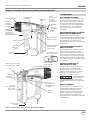
Set-Up
LUBRICATION
This nailer requires NO lubrication for normal operation. However, lubrication will
NOT harm the tool.
The work surface can become damaged by excessive lubrication.
MINIMUM COMPONENTS REQUIRED FOR HOOK-UP
AIR COMPRESSOR: The air compressor must be able to maintain a minimum of 70 psi
when the nailer is being used. An inadequate air supply can cause a loss of power and
inconsistent driving (see Chart 1).
PRESSURE REGULATOR: A pressure regulator is required to control the operating
pressure of the nailer between 70 psi and 120 psi.
AIR SUPPLY HOSE: ALWAYS use air supply hoses with a minimum working pressure
rating equal to or greater than the pressure from the power source, or 150 psi,
whichever is greater. Use 1/4 inch air hose for runs up to 50 feet. Use 3/8 inch air hoses
for 50 ft. run or longer (see Figure 7 and Chart 2).
HOOK-UP INSTRUCTIONS FOR NAILER TO AIR SUPPLY
Figure 8 shows the recommended hookup for the nailer.
NOTE: For better performance, install a 3/8 inch quick plug (1/4 inch NPT threads) with
an inside diameter of 0.315 inch (8 mm) on the nailer and a 3/8 inch quick coupler on
the air hose.
1. With ON/OFF switch in OFF position, plug compressor into electrical outlet.
2. Close pressure regulator by turning all the way to the left. Turn compressor ON and
let it pump all the way up to automatic shut-off pressure.
3. Attach air hose to regulator outlet. Adjust pressure regulator by turning to the right
so that outlet pressure is between 70 psi to 120 psi.
4. Load fasteners into nailer (See Loading/Unloading the Nailer section on page 11).
5. Point the nailer in a safe direction while attaching to air hose.
6. Nailer is ready for use. You may need to adjust outlet pressure to achieve proper
fastener depth.
70 psi Minimum
120 psi Maximum
Chart 1
Quick
Coupler
Air
Hose
Figure 8 - Recommended Hookup
Tank
Pressure
Gauge
Outlet
Pressure
Gauge
Regulator
Outlet
Regulator
Quick
Coupler
Quick
Plug
AIR HOSE REQUIREMENTS
DIAMETER LENGTH OF RUN
1/4 inch Less than 50 feet
3/8 inch Greater than or equal
to 50 feet
Chart 2
Figure 7 - Air Hose Requirements
Interior Diameter
Rated 150 psi or greater
Swivel
Plug

11
Operating Instructions and Parts Manual
www.chpower.com
LOADING / UNLOADING THE NAILER
Always disconnect the tool from the air supply before loading / unloading fasteners.
Choose which length of fastener you want to use for you project. Additional fasteners
can be found at major home centers.
Loading the Tool
1. Pull pusher back until it latches.
2. Insert nail clips into rear loading slot.
3. Press pusher latch button to release the pusher and allow it to engage the nail clip.
Unloading the Tool
1. Pull pusher back until it latches.
2. Dump the nails out the loading slot.
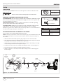
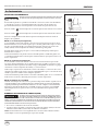
ADJUSTING THE NAIL PENETRATION
The CHN70500 is equipped with an adjustable depth of drive feature, ADC
thumbwheel (See Figure 11). This allows the user to determine how deep a fastener will
be driven into the work surface.
1. Adjust the operating pressure to a pressure which will consistently drive the
fasteners. Do not exceed the maximum operating pressure of the nailer of 120 psi.
2. To increase depth of drive, first pull up on the upper WCE, then rotate thumbwheel
to the left (counter-clockwise). To decrease depth of drive, rotate thumbwheel to the
right (clockwise). Then release upper WCE into detents which hold the thumbwheel
in place after each adjustment.
3. Make sure that the trigger and work contact element (WCE) move freely up and
down without binding or sticking after each adjustment.
ADJUSTING THE DIRECTION OF THE EXHAUST
The CHN70500 is equipped with an adjustable direction exhaust deflector. This is
intended to allow the user to change the direction of the exhaust. Simply twist the
deflector to any direction desired.
INSTALLING AND REMOVING NO-MAR / STUD FINDER TIP
1. Disconnect air supply from nailer.
2. Remove tip from retainer storage location.
3. Carefully place no-mar tip over the end of work contact element.
4. Check that the WCE and trigger move up and down freely without sticking or
binding.
NOTE: To remove the tip, reverse the proceedure listed above.
Set-Up (Continued)
CHN70500
Figure 12 - Exhaust Adjustment
Figure 11 - Nail Depth Adjust
Figure 13 - No-mar / Stud finder Tip
installed
No-mar tip
Stud finder
Figure 9 - Loading the Nailer
Figure 10 - Nail Bypass Button
Press
Button

Operating Instructions and Parts Manual
12
CHN70500
www.chpower.com
Pre-Operation
OPERATIONAL MODES
Always know the operational mode of the nailer before using. Failure to
know the operational mode could result in death or serious injury.
This nailer may be operated in the “Sequential” mode (as supplied by the
manufacturer) or “Bump” mode. the tool may be converted from one mode to the other
by firmly pressing the conversion switch from one position to the other.
Press the conversion switch to the “
” side to activate Sequential Mode.
Press the conversion switch to the “ ” side to activate Bump Mode.
Press either side to the middle position to activate the Safety Lockout Mode.
Sequential Mode (See Figure 14)
This method is recommended when precise nail placement is required. Operation in
this mode requires trigger to be pulled each time a nail is driven. Nailer can be actuated
by depressing the Work Contact Element (WCE) against work surface followed by
pulling the trigger.
The trigger must be released after each fastener is driven to allow tool to reset.
Since the tool can only be actuated by first removing the finger from the trigger, this
is considered to be a more restrictive mode of operation, suitable for less experienced
users.
Bump Mode (See Figure 15)
This method is recommended when less precise nail placement is required. Operation
in this mode requires trigger to be depressed with nailer off of the work surface. Then,
the nose of the nailer is tapped against the work surface causing a nail to be driven.
Each time the Work Contact Element is depressed, a nail is driven into the work
surface. Extreme care should be taken because a nail will be driven when the WCE is
pressed against any surface.
Since the tool can be actuated without removing the finger from the trigger, this is
considered to be a less restrictive mode, suitable for more experienced users.
Safety Lockout Mode
When the conversion switch is pressed into the middle position, the trigger is in Safety
Lockout Mode. In this mode, no combination of WCE and trigger activations will allow
the tool to cycle or fire. If tool does operate while in Safety Lockout Mode, contact
Campbell Hausfeld for technical support, and do not use the nailer until repaired.
WORK CONTACT ELEMENT (WCE)
Check the operation of the Work Contact Element (WCE) trip mechanism
before each use. The WCE must move freely without binding through its
entire travel distance. The WCE spring must return the WCE to its fully extended position after
being depressed. Do not operate the nailer if the WCE trip mechanism is not operating properly.
Personal injury may occur.
1. Disconnect the air supply from the nailer.
2. Make sure the trigger and Work Contact Element (WCE) move freely up and down
without sticking or binding.
NOTE: If the tool is not loaded with nails, the anti-dry fire feature will not allow the
WCE to be depressed.
3. Reconnect air supply to the nailer.
Figure 14 - Sequential Mode
Depress WCE first...
Work Surface
Then pull trigger.
Work Surface
Figure 15 - Bump Mode
Then depress WCE.
Work Surface
Pull trigger first...
Work Surface

13
Operating Instructions and Parts Manual
www.chpower.com
4. Use a scrap piece of wood as a work surface.
5. Depress the WCE against the work surface without pulling the trigger (See
Figure 16). The nailer MUST NOT OPERATE. Do not use the tool if it operates
without pulling the trigger. Personal injury may result.
6. Remove nailer from work surface. The WCE must return to its original down
position. Pull the trigger (See Figure 17). The nailer MUST NOT OPERATE. Do not
use the tool if it operates while lifted from the work surface. Personal injury may
result.
7. Pull the trigger and depress the WCE against the work surface. The nailer MUST
OPERATE when in bump mode. The nailer MUST NOT OPERATE if in sequential
mode.
8. Depress the WCE against work surface. Pull the trigger. The nailer MUST OPERATE.
9. Switch nailer into the other Mode as described in Operational Modes section and
repeat.
IMPORTANT: Repeat steps one through nine with tool in Safety Lockout Mode. Tool
SHOULD NOT operate at any step. If tool does operate while in Safety Lockout Mode,
contact Campbell Hausfeld for technical support.
ELECTRONICS ON / OFF SWITCH
Under the top of the rubber grip is an ON/ OFF switch for the tool’s electronic
functions, low nail indicator LEDs, and nail placement laser (See Figure 18).
To utilize the function, grip the tool by the handle firmly, depressing the switch in the
process. Power is maintained for 5 - 10 seconds after releasing the switch to provide
continuous, uninterrupted function during grip adjustments made by the user that
may temporarily release the switch.
Pre-Operation (Continued)
CHN70500
Work Surface
Figure 17
Work Surface
Figure 16
Figure 18 - Electronics ON / OFF Switch
Electronics
ON/OFF
Switch

Operating Instructions and Parts Manual
14
www.chpower.com
NAIL PLACEMENT LASER POINTER
The tool is equipped with a laser mounted near the nose. Turn the electronics switch
to the ON position. When the Work Contact Element (WCE) touches the workpiece and
slightly moves, the laser will shine on the spot where the nail will be driven. This can
be seen through the wide slots in the WCE and / or no-mar tip. When the laser is in the
desired location, simply fully press in the WCE and fire the tool.
This is a Class IIIA Laser Product that emits laser radiation.
Do not stare into beam or view directly with optical instruments.
FIRING THE NAILER
1. Load fasteners (see Loading / Unloading the Nailer section).
2. Connect the air supply to the nailer.
An improperly functioning tool must not be used. Do not actuate
the tool unless the tool is placed firmly against the work piece.
In Sequential Mode
Press the conversion switch to the “
” side to activate Sequential Mode.
1. Slightly depress Work Contact element (WCE) against work surface.
2. Laser pointer will shine on spot where nail will be driven when the WCE slightly
touches the work surface.
3. Fully depress WCE.
4. Pull trigger. Fastener will be driven into workpiece.
In Bump Mode
Press the conversion switch to the “
” side to activate Bump Mode.
1. Remove tool from work surface. DO NOT point tool at yourself or others.
2. Pull trigger.
3. Firmly depress Work Contact element (WCE) against work surface. Tool will cycle.
4. Remove tool from work surface. Move tool to the next area where fastener is to be
driven and repeat.
LOW NAIL INDICATOR LIGHTS (See Figure 20)
The tool is equipped with lights on either side of the tool near the nose. Turn the
electronics switch to the ON position. When the nail count becomes 10 or so nails
remaining in the magazine, the lights will come on yellow. You may reload at that time
(See Loading the Nailer section). When the nail count becomes 5 or so remaining nails,
the Anti-Dry Fire will engage and the lights will turn red. You MUST reload at that time.
BUBBLE LEVEL (See Figure 21)
The tool is equipped with a bubble level located on the head cap. When the gun is in a
horizontal driving orientation, a level condition can easily be observed and controlled
by simply aligning the tool in such a manner whereas the bubble is between the center
markings on the length of the level. The same is true when in a vertically downward
driving orientation by aligning the tool such that the bubble is centered in the circular
marking at the top of the level.
Operation
CHN70500
Figure 19 - Laser Pointer
Figure 20 - Low Nail Indicator Lights
Figure 21 - Bubble Level

15
Operating Instructions and Parts Manual
www.chpower.com
Operation (Continued)
CHN70500
Figure 24 - Clearing a jam
STUD FINDER
To find studs in walls, the no-mar tip also acts as a convenient stud finder with
operation similar to most common stud finders.
1. Disconnect tool from air supply.
2. If not already installed, put the no-mar tip on the Work Contact Element (WCE).
3. Load tool with fasteners (see Loading the Tool section).
4. Reconnect tool to air supply. Turn the electronics switch to the “ON” position.
5. Barely press the tip against the wall where no stud is nearby. Press the stud finder
operation button and hold (See Figure 22). Stud finder “plate” should be flat against
the wall.
6. The stud finder should beep and the stud finder indicator light will turn red for a
second while it calibrates. Once calibrated, the light should turn green. Do NOT
move the tool while the stud finder calibrates (See Figure 23).
7. When the light turns green, begin dragging the depressed WCE over the wall
“searching” for studs. When moved near the edge of a stud, the stud finder light will
begin to quickly flash a red light and the begin beeping quickly (See Figure 23).
8. When moved directly over a stud, the stud finder will emit a constant red light and
beep (See Figure 23).
NOTE: If tip is positioned directly over a stud during calibration, it will not calibrate
correctly. In this case, select another location on the wall to calibrate tool before using.
Storage
The nailer should be stored in a cool dry location with the batteries removed for long-
term storage.
Maintenance
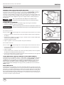
CLEARING A JAM FROM THE NAILER (See Figure 24)
1. Disconnect nailer from air supply.
2. Remove all nails from the magazine (see Loading/ Unloading). Failure to do so
may cause the nails to eject from the front of the nailer.
3. Undo latch by pulling cover in the direction shown.
4. The door can now be rotated, exposing the jammed fastener.
5. Remove the jammed fastener, using pliers or a screwdriver if required.
6 Rotate door back into the closed position.
7. Extend the latch and place over the hooks on the nose.
8. Close the latch by pushing the latch up and in until the latch snaps into place.
9. Load with nails.
10. Make sure the trigger and work contact element (WCE) move freely up and down
without sticking or binding.
NAILER REPAIR
Only qualified personnel should repair the tool and they should use genuine Campbell
Hausfeld replacement parts and accessories, or parts and accessories which perform
equivalently.
Figure 10 - Stud finder Operation Button
Figure 22
Stud finder
Operation Button
Figure 23
LED
Speaker
Stud finder
Laser Pointer

Operating Instructions and Parts Manual
16
CHN70500
www.chpower.com
REPLACEMENT PARTS
Use only genuine Campbell Hausfeld service parts. Tool performance,
safety and durability could be reduced if improper parts are used. When
ordering replacement parts, specify by part number.
BATTERY REPLACEMENT
Always disconnect the tool from the power source when unattended,
performing any maintenance or repair, clearing a jam, loading,
unloading , or moving the tool to a new location.
The electronics on the tool (low nail indicator lights and nail placement laser pointer)
run off of two (2) AAA batteries located in the compartment on the back of the
magazine. When the batteries’ power is running low and they need to be replaced,
the electronic functions may not work properly or at all. Disconnect the tool from air
source and remove the battery compartment cover by squeezing the locking tab and
pulling out. Insert two (2) new batteries in the proper orientation. Do not mix old and
new batteries. Close cover.
ASSEMBLY PROCEDURE FOR SEALS
When repairing a nailer, the internal parts must be cleaned and lubricated. Parker O-
lube or equivalent must be used on all o-rings. Each o-ring must be coated with O-lube
before assembling. A small amount of oil must be used on all moving surfaces and
pivots.
TECHNICAL SERVICE
For information regarding the operation or repair of this product, please call 1-800-
543-6400.
FASTENER INTERCHANGE INFORMATION
Fasteners used in the Campbell Hausfeld CHN70500 Angle Finish Nailer will also work
in the following brand units:
• Campbell Hausfeld NB0064 • Ridgid R250SFA
• Craftsman 18175, 18314 • Senco Finish Pro 32
• Porter Cable FN250
Maintenance (Continued)
Figure 25 - Battery Replacement
FASTENERS
The following Campbell Hausfeld brad nails are available at local retail stores. For help locating any item,
call customer service at 1-800-543-6400. Campbell Hausfeld nails meet or exceed ASTM Standard F1667.
Model # Length Shank Gauge Finish Head Collation Nails Per Stick Nails Per Box
FB005060 2 inch 16 Gauge Galvanized Brad Adhesive 50 2500
FB160025 1 inch 16 Gauge Galvanized Brad Adhesive 50 1000
FB160040 1-1/2 inch 16 Gauge Galvanized Brad Adhesive 50 1000
FB160050 2 inch 16 Gauge Galvanized Brad Adhesive 50 1000
FB160065 2-1/2 inch 16 Gauge Galvanized Brad Adhesive 50 1000

17
Operating Instructions and Parts Manual
www.chpower.com
Troubleshooting Guide
Stop using nailer immediately if any of the following problems occur. Serious personal injury could result.
Any repairs or replacements must be done by a Qualified Service Person or Authorized Service Center.
SYMPTOM CAUSE SOLUTION
Air leaking at trigger valve O-rings in trigger valve housing are
damaged
Replace O-rings. Check operation of Work Contact
Element (WCE)
Air leaking between housing
and nose
1. Damaged O-rings and / or seals 1. Replace O-rings and / or seals
2. Damage to bumper 2. Replace bumper
Air leaking between housing
and cap
1. Loose screws 1. Tighten screws
2. Damaged gasket 2. Replace gasket
Nailer skips driving nail 1. Worn bumper 1. Replace bumper
2. Dirt in nose piece 2. Clean drive channel
3. Dirt or damage prevent nails or
pusher from moving freely in
magazine
3. Clean magazine
4. Damaged pusher spring 4. Replace spring
5. Inadequate air flow to nailer 5. Check fitting, hose, or compressor
6. Worn O-ring on piston or lack of
lubrication
6. Replace piston seals
7. Damaged O-ring on trigger valve 7. Replace O-rings
8. Air leaks 8. Tighten screws and fitings
Nailer runs slow or has loss of
power
1. Nailer not lubricated sufficiently 1. Lubricate nailer
2. Broken spring in cylinder cap 2. Replace spring
3. Exhaust port in cap is blocked 3. Replace damaged internal parts
Nails are jammed in nailer 1. Guide on driver is worn 1. Replace guide
2. Nails are not correct type 2. Use only recommended nails
3. Nails are bent 3. Replace with undamaged nails
4. Magazine or nose screws are loose 4. Tighten screws
5. Driver is damaged 5. Replace driver
6. Nails loaded incorrectly 6. Review Loading / Unloading section of manual
Laser, low nail indicators,
and / or stud finder not
working
1. System power switch in grip not
depressed
1. Turn switch on
2. Batteries need to be replaced 2. Replace batteries (see “Changing batteries”
section)
3. Components not properly replaced
during re-assembly after customer
maintenance
3. Review parts view for assistance in proper re-
assembly
4. Laser won’t come on because WCE
not slightly depessed
4. Depress WCE to work surface
5. Studfinder not accurate 5. Make sure the sensor plate of studfinder is flat
against wall
CHN70500

18
Operating Instructions and Parts Manual
www.chpower.com
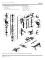
For Replacement Parts or Technical Assistance, Call 1-800-543-6400
Please provide following information: Address any correspondence to:
- Model number Campbell Hausfeld
- Serial number (if any) Attn: Customer Service
- Part description and number as shown in parts list 100 Production Drive
Harrison, OH 45030 U.S.A.
1
2
3
4
5
6
9
8
7
10
11
12
13
14
15
22
23
24
25
26
27
28
29
30
20
16
17
18
19
21
31
32
105
107
13
108
109
106
103
102
104
70
69
71
73
72
74
75
49
47
59
60
61
62
63
64
65
43
35
46
44
45
50
48
47
33
34
35
36
39
37
38
47
40
41
42
54
55
56
58
57
51
52
53
76
77
66
67
68
49
79
78
101
82
51
98
94
77
99
100
97
87
96
52
85
51
52
93
95
94
86
88
89
91
92
90
7
8
80
84
87
85
83
81
82
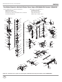
Figure 26 – Repair Parts Illustration for Air Powered Straight Finish Nailer, model CHN70500AV
CHN70500

19
CHN70500
www.chpower.com
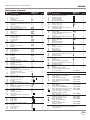
Replacement Parts List
1 Screw – M6 x 20 k 1
2 Bushing k 1
3 Exhaust cap — 1
4 Gasket l 1
5 Muffler assembly l 1
6 Bubble level s 1
7 Socket head cap screw – M5 x 25 k 6
8 Washer k 6
9 Cylinder cap — 1
10 Cylinder cap gasket n l 1
11 Valve spring n 1
12 O-ring n l 1
13 O-ring n l 2
14 Valve n 1
15 O-ring n l 1
16 Valve gasket n l 1
17 Screw – M6 x 12 n 1
18 Stop plate n 1
19 Piston ring l t 1
20 O-ring l t 1
21 Piston t 1
22 Driver blade t 1
23 Collar l u 1
24 Cylinder gasket l u 1
25 Cylinder — 1
26 O-ring l u 1
27 O-ring l u 1
28 Restricter plate u 1
29 O-ring l u 1
30 Bumper u 1
31 Body — 1
32 Nozzle l u 1
33 Thumbwheel H 1
34 Spring H 1
35 Ball bearing H
3
36 Upper work contact element H 1
37 Spring pin H 1
38 Spring H 1
39 Work contact element H 1
40 No-mar tip
1
41 Quick clear nose shroud D 1
42 Quick clear nose latch assembly D 1
43 Trigger mode switch
1
44 Spring 2
45 Screw – M4 x 5
2
46 Actuator 1
47 Retaining o-ring l H D 2
48 Spring pin H
1
49 Roll pin H 2
50 Spring pin H 1
51 Socket head cap screw – M4 x 8 3
52 Bushing 3
53 Electronics module
1
54 Latch D 1
55 Spring pin D 1
56 Quick clear nose door D 1
57 Roll pin D 1
58 Spring pin D 1
59 O-ring l
2
60 Trigger valve stem spring 1
61 Trigger valve 1
62 O-ring l
1
63 O-ring l 1
64 O-ring l
1
65 Trigger valve head 1
Ref. Part
No. Description No. Qty.
Ref. Part
No. Description No. Qty.
66 Screw – M4 x 10 2
67 Spring 1
68 Slide piece 1
69 O-ring l 1
70 O-ring l
1
71 Lower valve body 1
72 Spring pin 2
73 Trigger valve 1
74 Trigger spring
1
75 Trigger assembly 1
76 Screw 1
77 Screw – M4 x 10
3
78 Spring pin
1
79 Spring pin
1
80 Quick clear nose door bracket — 1
81 Drive guide plate — 1
82 Nut – M4
2
83 Work contact element locking piece 1
84 Spring 1
85 Socket head cap screw – M4 x 10 2
86 Screw – M4 x 8
1
87 Screw – M4 x 10 2
88 Pusher 1
89 Pusher seat 1
90 Pusher spring
1
91 Threaded sleeve 1
92 Pusher button 1
93 Spring pin 1
94 Nut – M4
6 3
95 Pusher plate 1
96 Lower magazine 1
97 Rail SV567700AV 1
98 Socket head cap screw – M4 x 12 6 2
99 Coil spring
1
100 Upper magazine 6 1
101 Recoil decal housing 1
102 Nut – M5 6 1
103 Magazine end cap 6 1
104 Socket head cap screw – M5 x 16 6 1
105 Spring pin k 1
106 Spring pin k 1
107 Grip — 1
108 Inlet end cap — 1
109 1/4-18 i/m (m) swivel plug SV567600AV 1
REPLACEMENT PARTS KITS
s Bubble level kit SKN22000AV
n Head valve repair kit SKN22100AV
l Complete seal kit SKN22200AV
u Cylinder repair kit SKN22300AV
t Driver assembly kit SKN22400AV
H Work contact element (WCE) kit SKN22500AV
D Quick clear nose (QCN) kit SKN22600AV
Trigger mode switch kit SKN22700AV
Trigger repair kit SKN22800AV
Electronics module kit
(some soldering required) SKN22900AV
Recoil warning decal kit SKN23000AV
Anti dry fire kit SKN23100AV
Pusher kit SKN23200AV
Lower magazine assembly kit SKN23300AV
6 Upper magazine assembly kit SKN23400AV
— Not Available
k Standard hardware item - available at your local
hardware store
Operating Instructions and Parts Manual

20
Operating Instructions and Parts Manual
www.chpower.com
Reminder: Keep your dated proof of purchase for warranty purposes! Attach it to this manual or file it for safekeeping.
Warranty
1. DURATION: From the date of purchase by the original purchaser as follows: One Year.
2. WHO GIVES THIS WARRANTY (WARRANTOR): Campbell Hausfeld / Scott Fetzer Company, 100 Production Drive, Harrison,
Ohio, 45030, Telephone: (800) 543-6400
3. WHO RECEIVES THIS WARRANTY (PURCHASER): The original purchaser (other than for purposes of resale) of the Campbell
Hausfeld product.
4. WHAT PRODUCTS ARE COVERED BY THIS WARRANTY: Any Campbell Hausfeld nailer, stapler, air tool, spray gun, inflator or air
accessory supplied or manufactured by Warrantor.
5. WHAT IS COVERED UNDER THIS WARRANTY: Substantial defects in material and workmanship which occur within the
duration of the warranty period.
6. WHAT IS NOT COVERED UNDER THIS WARRANTY:
A. Implied warranties, including those of merchantability and FITNESS FOR A PARTICULAR PURPOSE ARE LIMITED FROM
THE DATE OF ORIGINAL PURCHASE AS STATED IN THE DURATION. If this product is used for commercial, industrial or
rental purposes, the warranty will apply for ninety (90) days from the date of purchase. Some States do not allow limitation
on how long an implied warranty lasts, so the above limitations may not apply to you.
B. ANY INCIDENTAL, INDIRECT, OR CONSEQUENTIAL LOSS, DAMAGE, OR EXPENSE THAT MAY RESULT FROM ANY
DEFECT, FAILURE, OR MALFUNCTION OF THE CAMPBELL HAUSFELD PRODUCT. Some States do not allow the
exclusion or limitation of incidental or consequential damages, so the above limitation or exclusion may not apply to you.
C. Any failure that results from an accident, purchaser’s abuse, neglect or failure to operate products in accordance with
instructions provided in the owner’s manual(s) supplied with product. Accident, purchaser’s abuse, neglect or failure to
operate products in accordance with instructions shall also include the removal or alteration of any safety devices. If such
safety devices are removed or altered, this warranty is void.
D. Normal adjustments which are explained in the owner’s manual(s) provided with the product.
E. Items or service that are normally required to maintain the product, i.e. o-rings, springs, bumpers, debris shields, driver
blades, fuses, batteries, gaskets, packings or seals, fluid nozzles, needles, sandblast nozzles, lubricants, material hoses, filter
elements, motor vanes, abrasives, blades, cut-off wheels, chisels, chisel retainers, cutters, collets, chucks, rivet jaws, screw
driver bits, sanding pads, back-up pads, impact mechanism, or any other expendable part not specifically listed. These
items will only be covered for ninety (90) days from date of original purchase. Underlined items are warranted for defects in
material and workmanship only.
7. RESPONSIBILITIES OF WARRANTOR UNDER THIS WARRANTY: Repair or replace, at Warrantor’s option, products or
components which are defective, have malfunctioned and/or failed to conform within duration of the warranty period.
8. RESPONSIBILITIES OF PURCHASER UNDER THIS WARRANTY:
A. Provide dated proof of purchase and maintenance records.
B. Call Campbell Hausfeld (800) 543-6400 to obtain your warranty service options. Freight costs must be borne by the
purchaser.
C. Use reasonable care in the operation and maintenance of the products as described in the owner’s manual(s).
9. WHEN WARRANTOR WILL PERFORM REPAIR OR REPLACEMENT UNDER THIS WARRANTY: Repair or replacement will
be scheduled and serviced according to the normal work flow at the servicing location, and depending on the availability of
replacement parts.
This Limited Warranty applies in the United States, Canada and Mexico only and gives you specific legal rights. You may also have
other rights which vary from state to state or country to country.
CHN70500
Page is loading ...
Page is loading ...
Page is loading ...
Page is loading ...
Page is loading ...
Page is loading ...
Page is loading ...
Page is loading ...
Page is loading ...
Page is loading ...
Page is loading ...
Page is loading ...
Page is loading ...
Page is loading ...
Page is loading ...
Page is loading ...
Page is loading ...
Page is loading ...
Page is loading ...
Page is loading ...
Page is loading ...
Page is loading ...
Page is loading ...
Page is loading ...
Page is loading ...
Page is loading ...
Page is loading ...
Page is loading ...
Page is loading ...
Page is loading ...
Page is loading ...
Page is loading ...
Page is loading ...
Page is loading ...
Page is loading ...
Page is loading ...
Page is loading ...
Page is loading ...
Page is loading ...
Page is loading ...
-
 1
1
-
 2
2
-
 3
3
-
 4
4
-
 5
5
-
 6
6
-
 7
7
-
 8
8
-
 9
9
-
 10
10
-
 11
11
-
 12
12
-
 13
13
-
 14
14
-
 15
15
-
 16
16
-
 17
17
-
 18
18
-
 19
19
-
 20
20
-
 21
21
-
 22
22
-
 23
23
-
 24
24
-
 25
25
-
 26
26
-
 27
27
-
 28
28
-
 29
29
-
 30
30
-
 31
31
-
 32
32
-
 33
33
-
 34
34
-
 35
35
-
 36
36
-
 37
37
-
 38
38
-
 39
39
-
 40
40
-
 41
41
-
 42
42
-
 43
43
-
 44
44
-
 45
45
-
 46
46
-
 47
47
-
 48
48
-
 49
49
-
 50
50
-
 51
51
-
 52
52
-
 53
53
-
 54
54
-
 55
55
-
 56
56
-
 57
57
-
 58
58
-
 59
59
-
 60
60


Campbell Hausfeld CHN70500 User manual
- Category
- Power tools
- Type
- User manual
- This manual is also suitable for
Ask a question and I''ll find the answer in the document
Finding information in a document is now easier with AI
in other languages
Related papers
-
Campbell Hausfeld CHN10500 Operating instructions
-
-
-
-
-
-
-
-
-
Other documents
-
Stanley FMC792 User manual
-
 Maxus MXN10100 User manual
-
MasterCraft AIR-POWERED BRAD NAILERS User manual
-
Husky HD219000 User manual
-
Stanley SFMCN616 Owner's manual
-
-
 Maxus MXN064 User manual
-
-
-

