Page is loading ...
Page is loading ...
Page is loading ...
Page is loading ...
Page is loading ...
Page is loading ...
Page is loading ...
Page is loading ...
Page is loading ...
Page is loading ...
Page is loading ...

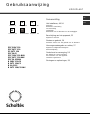
HOB
PPF 20DC 120
PPF 30TC 120
PP 30TC 120
PPF 20 65
PPF 20DC 120 BNV
PPF 30TC 120 BNV
PPF 20 65 BNV
B 20DC 120/CS
B 30TC 120/CS
B 20 65/CS
B 30TC 138/CS BNV
Operating Instructions
Italiano, 1 Français, 23English,12
IT FR
GB
GB
Deutsch, 35
Español , 60
Nederlands,47
NLDE ES
Contents
Installation, 13-17
Positioning
Electrical connection
Gas connection
Data plate
Burner and nozzle specifications
Description of the appliance, 18
Overall view
Start-up and use, 19
Practical advice on using the burners
Precautions and tips, 20
General safety
Disposal
Maintenance and care, 21
Switching the appliance off
Cleaning the appliance
Gas tap maintenance
Troubleshooting, 22

GB
13
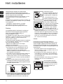
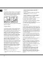
! Before operating your new appliance please read this
instruction booklet carefully. It contains important
information for safe use, installation and care of the
appliance.
! Please keep these operating instructions for future
reference. Pass them on to possible new owners of the
appliance.
Positioning
! Keep packaging material out of the reach of children. It
can become a choking or suffocation hazard (see
Precautions and tips).
! The appliance must be installed by a qualified
professional according to the instructions provided.
Incorrect installation may cause harm to people and
animals or may damage property.
! This unit may be installed and used only in permanently
ventilated rooms in accordance with British Standard
Codes Of Practice: B.S. 6172 / B.S. 5440, Par. 2 and B.S.
6891 Current Editions. The following requirements must be
observed:
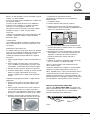
• The room must be equipped with an air extraction
system that expels any combustion fumes. This may
consist of a hood or an electric fan that automatically
starts each time the appliance is switched on.
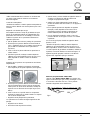
• The room must also allow proper air circulation, as air is
needed for combustion to occur normally. The flow of air
must not be less than 2 m3/h per kW of installed power.
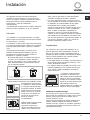
The air circulation system may
take air directly from the outside
by means of a pipe with an inner
cross section of at least 100
cm2; the opening must not be
vulnerable to any type of
blockages.
The system can also provide the
air needed for combustion
indirectly, i.e. from adjacent rooms
fitted with air circulation tubes as
described above. However, these
rooms must not be communal
rooms, bedrooms or rooms that
may present a fire hazard.
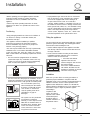
• Liquid petroleum gas sinks to the floor as it is heavier
than air. Therefore, rooms containing LPG cylinders
must also be equipped with vents to allow gas to
escape in the event of a leak. As a result LPG
cylinders, whether partially or completely full, must not
be installed or stored in rooms or storage areas that are
below ground level (cellars, etc.). It is advisable to keep
only the cylinder being used in the room, positioned so
that it is not subject to heat produced by external
sources (ovens, fireplaces, stoves, etc. ) which could
raise the temperature of the cylinder above 50°C.
Fitting the appliance
Gas and mixed hobs are manufactured with type X degree
protection against overheating. The following precautions
must be taken when installing the hob:
• Kitchen cabinets adjacent to the appliance and taller
than the top of the hob must be at least 600 mm from
the edge of the hob.
• Hoods must be installed according to their relative
installation instruction manuals and at a minimum
distance of 650 mm from the hob.
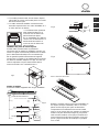
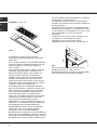
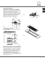
• Place the wall cabinets
adjacent to the hood at a
minimum height of 420 mm from
the hob (see figure).
If the hob is installed beneath a
wall cabinet, the latter must be
situated at a minimum of 700 mm
above the hob (see figure).
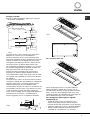
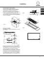
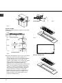
Installation
Make sure you take all the necessary precautions to
guarantee proper installation in compliance with the
applicable norms in force regarding accident-prevention for
electrical connection. For the correct operation of the
appliance when built into the cabinet, it is vital that the
minimum distances illustrated in Fig. 1 be respected. The
hob features a type Y degree of protection against
overheating in
compliance with
norms. All surfaces
adjacent to the cabinet
and the back panel
should be made of
materials resistant to a
temperature of 65°C.
Installation
Enlarging the ventilation slot
between window and floor.
Adjacent
Room
Room to be
Vented
A
Examples of ventilation holes
for comburant air.
In a chimney stack or branched flue.
(exclusively for cooking appliances)
Directly to
the Outside
600mm min.
540mm min.
700mm min.
85 min
700 min
50 min
Fig.1

GB
14
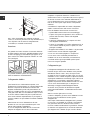
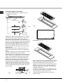
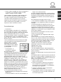
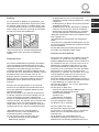
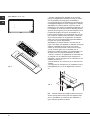
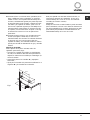
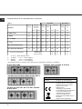
Securing the appliance to the cabinet
There are three different groups of appliance as far as
installation is concerned:
1-Built-in hobs flush with the worktop (Class 3 - see figure
2, detail H1). In this case it is necessary to make a hole
with measurements matching those of the hob in the
worktop. The measurement at the side should be reduced
by 2 cm so as to ensure that 1 cm of the hob overlaps with
and rests on top of the supporting surface (see figure 3). To
fit the hob flush with the worktop, it is necessary to cut
lower on this supporting surface (see figure 3 and 4), so
that both the edge of the hob and the seal under it can be
positioned there.
Before fitting the hob to the worktop, position the seal
provided along the perimeter of the hob, as illustrated in fi-
gure 4.
Brackets for fixing hobs to the cabinet have been provided,
and these should be fitted as shown in detail S.
2-Built-in hobs (Class 3) with edges lower than 58 mm (see
figure 2, detail H2). To install this type of hob, a hole large
enough to accommodate the whole lower casing of the
appliance must be made on the worktop intended to be
under the hob. Remember to leave a gap of at least 1 cm
between the lower casing and the worktop around the
whole perimeter of the appliance (the underside of the
casing can, however, touch the surface below it). To fit the
appliances, follow the instructions given above in point 1 or
use any supplementary instruction leaflet that is provided
in special cases.
BUILT-IN HOB
HEIGHT= STEEL THICKNESS
BUILT-IN HOB
STEEL TICKNESS <HEIGHT <58mm
SIT ON - ON HOB
HEIGHT >58mm
fig.2
fig 3
TOP
10mm
S
2,5mm
Y
X
Y+2mm
X+2mm
R 11mm
X-20mm
Y-20mm
360 mm
1160 mm
345 mm
1145 mm
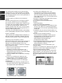
For model PP 30TC 120:
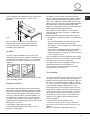
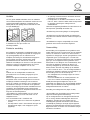
3-Sit-on hobs (Class 1) with edges higher than 58 mm (see
figure 2, detail H3). In this case, the lower casing of the
hob does not protrude further than the edge of the
appliance. Even when the hob is resting on the worktop, it
will suffice to leave space for the gas supply tube and
electricity supply cable. To fit this type of hob, follow the
instructions below (fig. 5):
• Fix the two screws provided "A" at a distance from the
back panel as shown in figure 7, leaving the heads of the
screws sticking out of the wood by 1.5 mm.
• Hook the hob onto the two screws "A" and push it
towards the back.
fig.4

GB
15
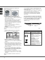
Ventilation
To ensure adequate ventilation, the back panel of the
cabinet must be removed. It is advisable to install the oven
so that it rests on two strips of wood, or on a completely
flat surface with an opening of at least 45 x 560 mm (see
diagrams).
! The hob can only be installed above built-in ovens with a
cooling ventilation system.
Electrical connection
Hobs equipped with a three-pole power supply cable are
designed to operate with alternating current at the voltage
and frequency indicated on the data plate (this is located
on the lower part of the appliance). The earth wire in the
cable has a green and yellow cover. If the appliance is to
be installed above a built-in electric oven, the electrical
connection of the hob and the oven must be carried out
separately, both for electrical safety purposes and to make
extracting the oven easier.
Connecting the supply cable to the mains
Install a standardised plug corresponding to the load
indicated on the data plate.
The appliance must be directly connected to the mains
using an omnipolar circuit-breaker with a minimum contact
opening of 3 mm installed between the appliance and the
mains. The circuit-breaker must be suitable for the charge
indicated and must comply with current electrical regulations
(the earthing wire must not be interrupted by the circuit-
breaker). The supply cable must not come into contact with
surfaces with temperatures higher than 50°C.
! The installer must ensure that the correct electrical
connection has been made and that it is compliant with
safety regulations.
Before connecting to the power supply, make sure that:
• The appliance is earthed and the plug is compliant with
the law.
• The socket can withstand the maximum power of the
appliance, which is indicated on the data plate.
• The voltage is in the range between the values indicated
on the data plate.
• The socket is compatible with the plug of the appliance.
If the socket is incompatible with the plug, ask an
authorised technician to replace it. Do not use extension
cords or multiple sockets.
! Once the appliance has been installed, the power supply
cable and the electrical socket must be easily accessible.
! The cable must not be bent or compressed.
! The cable must be checked regularly and replaced by
authorised technicians only (see Assistance).
! The manufacturer declines any liability should these
safety measures not be observed.
Gas connection
The appliance should be connected to the main gas supply
or to a gas cylinder in compliance with current national
regulations. Before carrying out the connection, make sure
the cooker is compatible with the gas supply you wish to
use. If this is not the case, follow the instructions indicated
in the paragraph “Adapting to different types of gas.”
When using liquid gas from a cylinder, install a pressure
regulator which complies with current national regulations.
! Check that the pressure of the gas supply is consistent
with the values indicated in Table 1 (“Burner and nozzle
specifications”). This will ensure the safe operation and
longevity of your appliance while maintaining efficient
energy consumption.
Connection with a rigid pipe (copper or steel)
! Connection to the gas system must be carried out in
such a way as not to place any strain of any kind on the
appliance.
There is an adjustable L-shaped pipe fitting on the
560 mm.
45 mm.
1.5 mm
1.5
mm
A
B
C
X
mm
• Fix the appliance to the cabinet at the rear, using the two
brackets "B" and the four screws "C" (these are all
provided).
N.B.: to maximise the efficiency of all maintenance
operations, the area around the hob must be easily
accessible after it has been installed (i.e. there are no
completely shut-off elements).
Fig.5

GB
16
appliance supply ramp and this is fitted with a seal in order
to prevent leaks. The seal must always be replaced after
rotating the pipe fitting (seal provided with appliance). The
gas supply pipe fitting is a threaded 1/2 gas cylindrical
male attachment.
Connecting a flexible jointless stainless steel pipe to a
threaded attachment
The gas supply pipe fitting is a threaded 1/2 gas cylindrical
male attachment.
These pipes must be installed so that they are never
longer than 2000 mm when fully extended. Once
connection has been carried out, make sure that the
flexible metal pipe does not touch any moving parts and is
not compressed.
! Only use pipes and seals that comply with current
national regulations.
Checking the tightness of the connection
! When the installation process is complete, check the pipe
fittings for leaks using a soapy solution. Never use a
flame.
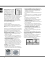
Adapting to different types of gas
To adapt the hob to a different type of gas other than
default type (indicated on the rating plate at the base of the
hob or on the packaging), the burner nozzles should be
replaced as follows:
1. Remove the hob grids and slide the burners off their
seats.
2. Unscrew the nozzles using a 7 mm socket spanner, and
replace them with nozzles for the new type of gas (see
table 1 “Burner and nozzle characteristics”).
3. Reassemble the parts following the above procedure in
the reverse order.
4. Once this procedure is finished, replace the old rating
sticker with one indicating the new type of gas used.
Sticker are available from any of our Service Centres.
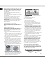
Replacing the nozzles on separate “double flame “ burners:
1. remove the grids and slide the burners from their
housings. The burner consists of 2 separate parts (see
figure);
2. unscrew the burers with a 7 mm wrench spanner. The
internal burner has a nozzle, the external burner has two
(of the same size). Replace the nozzle with models
suited to the new type of gas (see table 1).
3. replace all the components by repeating the steps in
reverse order
• Adjusting the burners’ primary air :
Does not require adjusting.
• Setting the burners to minimum:
1. Turn the tap to the low flame position.
2. Remove the knob and adjust the adjustment screw,
which is positioned in or next to the tap pin, until the
flame is small but steady.
3. Having adjusted the flame to the required low setting,
while the burner is alight, quickly change the position of
the knob from minimum to maximum and vice versa
several times, checking that the flame does not go out.
4. Some appliances have a safety device (thermocouple)
fitted. If the device fails to work when the burners are
set to the low flame setting, increase this low flame
setting using the adjusting screw.
5. Once the adjustment has been made, replace the seals
on the by-passes using sealing wax or a similar
substance.
! If the appliance is connected to liquid gas, the regulation
screw must be fastened as tightly as possible.
! Once this procedure is finished, replace the old rating
sticker with one indicating the new type of gas used.
Stickers are available from any of our Service Centres.
! Should the gas pressure used be different (or vary
slightly) from the recommended pressure, a suitable
pressure regulator must be fitted to the inlet pipe (in order
to comply with current national regulations).
Note for hob model B 30TC 138/CS BNV only
B 30TC 138/CS BNV model hobs are equipped with two
gas supply inlets (see fig. 6, details P1 and P2) and each
one controls two burners; both inlets should therefore be
connected to the gas supply network.
R1 R2
Fig.6

GB
17
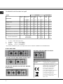
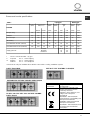
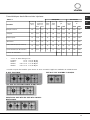
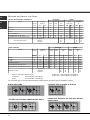
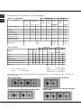
Burner and nozzle specifications
Table 1 Liquid gas Natural gas
BURNER
Diameter
(mm)
Thermal power
kW (H.s.*)
By-pass
1/100
(mm)
Injector
1/100
(mm)
Flow *
g/h
Injector
1/100
(mm)
Flow*
l/h
Nomin. Reduc. G30 G31 G20
D.
Triple Ring
130 3.25 1.3 57 91 236 232 124 309
C.
Rapid
100 3.00 0.7 40 86 218 214 116 286
B.
Semi-rapid
75 1.65 0.4 30 64 120 118 96 157
A.
Auxiliary
55 1.00 0.4 30 50 73 71 71 95
I.
Double flame DC DR (internal)
30 0.90 0.4 30 44 65 64 70 86
I.
Double Flame DC DR (external)
130 4.10 1.3 57 70 298 293 110 390
Supply pressure
Nominal
Minimum
Maximum
28-30
20
35
37
25
45
20
17
25
* At 15°C and 1013 mbar - dry gas
** Propane P.C.S. = 50.37 MJ/Kg
*** Butane P.C.S. = 49.47 MJ/Kg
Natural P.C.S. = 37.78 MJ/m3
! The hob can only be installed above built-in ovens with a cooling ventilation system.
DATA PLATE
Electrical
connections
voltage of 220-240V ~ 50/60Hz
(see data plate )
This appliance conforms to the
following European Economic
Community directives:
-73/23/EEC dated 19/02/73 (Low
Voltage) and subsequent
amendments
- 89/336/EEC dated 03/05/89
(Electromagnetic Compatibility) and
subsequent amendments
- 93/68/EEC dated 22/07/93 and
subsequent amendments.
- 90/336/EEC dated 29/06/90 (Gas)
and subsequent amendments.
- 2002/96/EC
ICA
C
B
D
A
C
A
PPF 20 65 - PPF 20 65 BNV - B 20 65/CS
PP 30TC 120 - PPF 30TC 120 - PPF 30TC 120 BNV -
B 30TC 120/CS
PPF 20DC 120 - PPF 20DC 120 BNV - B 20DC 120/CS
B
D
A
C
B 30TC 138/CS BNV

GB
18
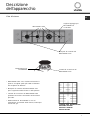
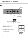
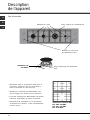
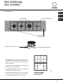
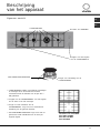
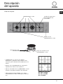
Description of the appliance
Overall view
GAS BURNERS
Support Grid for
COOKWARE*
Control Knobs for
GAS BURNERS
SAFETY
DEVICES
Ignition for
GAS BURNERS
• GAS BURNERS differ in size and power. Use the
diameter of the cookware to choose the most
appropriate burner to cook with.
• Control Knobs for GAS BURNERS adjust the
power or the size of the flame.
• GAS BURNER ignition enables a specific burner to
be lit automatically.
• SAFETY DEVICE stops the gas flow if the flame
is accidentally extinguished.
*Grids for BNV models
PPF 20DC 120 BNV
PPF 30TC 120 BNV
PPF 20 65 BNV

GB
19
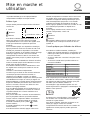
! The position of the corresponding gas burner or
electric hotplate is shown on every knob.
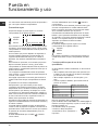
Gas burners
Each burner can be adjusted to one of the following
settings using the corresponding control knob:
0 Off
Maximum
Minimum
To light one of the burners, hold a lit match or lighter
near the burner and, at the same time, press down
and turn the corresponding knob anti-clockwise to the
maximum setting.
Since the burner is fitted with a safety device, the
knob should be pressed for approximately 2-3
seconds to allow the automatic device keeping the
flame alight to heat up.
When using models with an ignition button, light the
desired burner pressing down the corresponding knob
as far as possible and turning it anticlockwise
towards the maximum setting.
! If a flame is accidentally extinguished, turn off the
control knob and wait for at least 1 minute before
trying to relight it.
To switch off the burner, turn the knob in a clockwise
direction until it stops (when reaches the “0” position).
The “separate double flame” burner*:
This burner consists of two concentric burners which
can operate either together or separately.
Use of the double flame on the maximum setting
gives a very high power which reduces cooking times
with respect to conventional burners.
Moreover the double flame crown provides a more
uniform distribution of heat on the bottom of the pan,
when using both burners on minimum.
To ensure that the double-flame burner is used to its
full potential, never set the inside ring to minimum
and the outside ring to maximum at the same time.
Pots and pans of all sizes can be used. In the case
of the smaller pots and pans we recommend the use
of only the internal burner.
There is a separate control knob for each of the
“separate double flame” burners.
The knob marked by the symbol
operates the
external burner;
The knob marked by the symbol
operates the
internal burner.
To turn on one of the rings, press the relative knob in
all the way and turn it anti-clockwise to the high
setting. The burner is fitted with an electronic igniter
that automatically starts when the knob is pressed
in.
Since the burner is equipped with a safety device,
after lighting the burner keep the knob pressed in for
about 2-3 seconds to allow the device which keeps
the flame lit automatically to heat up.
The selected burner can be regulated using the
corresponding knob, as follows:
0 Off
Maximum
Minimum
To switch off the burner, turn the knob in a clockwise
direction until it stops (when reaches the “0” position).
Practical advice on using the burners
To ensure the burners operate efficiently:
• Use appropriate cookware for each burner (see
table) so that the flames do not extend beyond the
bottom of the cookware.
• Always use cookware with a flat base and a cover.
• When the contents of the pan reach boiling point,
turn the knob to minimum.
Note: for hob model B 30TC 138/CS BNV only
B 30TC 138/CS BNV model hobs are fitted with a
reducer shelf (see the figure below), which may only
be used in conjunction with the auxiliary burner "A".
To identify the type of burner, refer to the designs in
the section entitled, "Burner and Nozzle
Specifications".
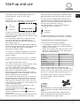
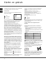
Start-up and use
Burner ø Pan Diameter (cm)
A.Auxiliary
6 – 14
B.Semi-rapid
15 – 20
C.Rapid
21 – 26
D. Triple ring
24 - 26
I.Double ring DC-DR (inner)
10 - 14
I.Double ring DC-DR (outer)
24 - 28
(models PPF...BNV...)
0
Note When there is no electricity supply, the burners can be
lit with a match after turning the control knob to the flame
position.
To turn on one of the burners, place a lighted match or
lighter near the burner, press the knob all the way in and
turn it anti-clockwise to the "High" setting.
Note

GB
20
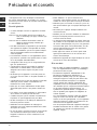
Precautions and tips
! This appliance has been designed and manufactured
in compliance with international safety standards. The
following warnings are provided for safety reasons and
must be read carefully.
General safety
• This is a appliance.
-Class 1: all models with edges that are higher than 58
mm (see overleaf, fig. 4, detail H3).
-Class 3: all models with edges that are lower than 58
mm (see overleaf, fig. 4, details H1 and
H2).
• Gas appliances require regular air exchange to
maintain efficient operation. When installing the
hob, follow the instructions provided in the
paragraph on “Positioning” the appliance.
• These instructions are only valid for the countries
whose symbols appear in the manual and on the
serial number plate.
• The appliance was designed for domestic use
inside the home and is not intended for commercial
or industrial use.
• The appliance must not be installed outdoors, even
in covered areas. It is extremely dangerous to leave
the appliance exposed to rain and storms.
• Do not touch the appliance with bare feet or with
wet or damp hands and feet.
• The appliance must be used by adults only, to cook
food according to the instructions in this manual.
• Ensure that the power supply cables of other
electrical appliances do not come into contact with
the hot parts of the oven.
• The openings used for ventilation and dispersion of
heat must never be covered.
• Always make sure the knobs are in the “0” position
when the appliance is not in use.
• When unplugging the appliance always pull the plug
from the mains socket, do not pull on the cable.
• Never carry out any cleaning or maintenance work
without having detached the plug from the mains.
• In case of malfunction, under no circumstances
should you attempt to repair the appliance yourself.
Repairs carried out by inexperienced persons may
cause injury or further malfunctioning of the
appliance. Contact a Service Centre (see
Assistance).
• Always make sure that pan handles are turned
towards the centre of the hob in order to avoid
accidental burns.
• Do not close the glass cover (if present) when the
gas burners or electric hotplates are still hot.
• Do not leave the electric hotplate switched on
without a pan placed on it.
• Do not use unstable or deformed pans.
• Remove any liquid from the lid before opening it.
• Prevent children and the disabled from coming into
contact or having access at the ceramic glass
cooking surface (if present) immediately before
and after use, as the cooking surface will remain
hot for at least a half hour after being turned off;
• Contact service centers authorized by the
manufacturer in the event the ceramic glass
cooking surface breaks.
• It is recommended that you follow the guidelines
below:
• Disconnect the appliance from the electrical
supply in the event the ceramic glass cooking
surface breakds.
Disposal
• When disposing of packaging material: observe
local legislation so that the packaging may be
reused.
• The European Directive 2002/96/EC on Waste
Electrical and Electronic Equipment (WEEE),
requires that old household electrical appliances
must not be disposed of in the normal unsorted
municipal waste stream. Old appliances must be
collected separately in order to optimise the
recovery and recycling of the materials they
contain and reduce the impact on human health
and the environment. The crossed out “wheeled
bin” symbol on the product reminds you of your
obligation, that when you dispose of the appliance
it must be separately collected.
Consumers may take their old appliance to public
waste collection areas, other communal collection
areas, or if national legislation allows return it to a
retailer when purchasing a similar new product.
All major household appliance manufacturers are
active in the creation of systems to manage the
collection and disposal of old appliances.

GB
21
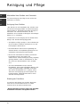
Switching the appliance off
Disconnect your appliance from the electricity supply
before carrying out any work on it.
Cleaning the appliance
! Do not use abrasive or corrosive detergents such
as stain removers, anti-rust products, powder
detergents or sponges with abrasive surfaces: these
may scratch the surface beyond repair.
! Never use steam cleaners or pressure cleaners on
the appliance.
• It is usually enough to wash the hob with a damp
sponge and dry it with absorbent kitchen roll.
• The removable parts of the burners should be
washed frequently with warm water and soap and
any burnt-on substances removed.
• For hobs which ligth automatically, the terminal
part of the electronic instant lighting devices
should be cleaned frequently and the gas outlet
holes should be checked for blockages.
• Stainless steel can be marked by hard water that
has been left on the surface for a long time, or by
aggressive detergents containing phosphorus.
After cleaning, rinse and dry any remaining drops
of water.
Gas tap maintenance
Over time, the taps may become jammed or difficult
to turn. If this happens, the tap must be replaced.
! This procedure must be performed by a qualified
technician authorised by the manufacturer.
Maintenance and care

GB
22
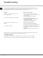
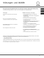
Troubleshooting
It may happen that the appliance does not function properly or at all. Before calling the service centre for
assistance, check if anything can be done. First, check to see that there are no interruptions in the gas and
electrical supplies, and, in particular, that the gas valves for the mains are open.
Problem
The burner does not light or the flame is not
even around the burner.
The flame dies in models with a safety device.
The burner does not remain lit when set to
minimum.
The cookware is unstable.
Possible causes/Solution
• The gas holes on the burner are clogged.
• All the movable parts that make up the burner are
mounted correctly.
• There are draughts near the appliance.
• You pressed the knob all the way in.
• You keep the knob pressed in long enough to
activate the safety device.
• The gas holes are not blocked in the area
corresponding to the safety device.
• The gas holes are not blocked.
• There are no draughts near the appliance.
• The minimum setting has been adjusted properly.
• The bottom of the cookware is perfectly flat.
• The cookware is positioned correctly at the centre
of the burner.
• The pan support grids have been positioned
correctly.
If, despite all these checks, the hob does not function properly and the problem persists, call the nearest
Customer Service Centre. Please have the following information handy:
• The appliance model (Mod.).
• The serial number (S/N).
This information can be found on the data plate located on the appliance and/or on the packaging.
! Never use unauthorised technicians and never accept replacement parts which are not original.
Page is loading ...
Page is loading ...
Page is loading ...
Page is loading ...
Page is loading ...
Page is loading ...
Page is loading ...
Page is loading ...
Page is loading ...
Page is loading ...
Page is loading ...
Page is loading ...
Page is loading ...
Page is loading ...
Page is loading ...
Page is loading ...
Page is loading ...
Page is loading ...
Page is loading ...
Page is loading ...
Page is loading ...
Page is loading ...
Page is loading ...
Page is loading ...
Page is loading ...
Page is loading ...
Page is loading ...
Page is loading ...
Page is loading ...
Page is loading ...
Page is loading ...
Page is loading ...
Page is loading ...
Page is loading ...
Page is loading ...
Page is loading ...
Page is loading ...
Page is loading ...
Page is loading ...
Page is loading ...
Page is loading ...
Page is loading ...
Page is loading ...
Page is loading ...
Page is loading ...
Page is loading ...
Page is loading ...
Page is loading ...
Page is loading ...
Page is loading ...
Page is loading ...
Page is loading ...
Page is loading ...
Page is loading ...
-
 1
1
-
 2
2
-
 3
3
-
 4
4
-
 5
5
-
 6
6
-
 7
7
-
 8
8
-
 9
9
-
 10
10
-
 11
11
-
 12
12
-
 13
13
-
 14
14
-
 15
15
-
 16
16
-
 17
17
-
 18
18
-
 19
19
-
 20
20
-
 21
21
-
 22
22
-
 23
23
-
 24
24
-
 25
25
-
 26
26
-
 27
27
-
 28
28
-
 29
29
-
 30
30
-
 31
31
-
 32
32
-
 33
33
-
 34
34
-
 35
35
-
 36
36
-
 37
37
-
 38
38
-
 39
39
-
 40
40
-
 41
41
-
 42
42
-
 43
43
-
 44
44
-
 45
45
-
 46
46
-
 47
47
-
 48
48
-
 49
49
-
 50
50
-
 51
51
-
 52
52
-
 53
53
-
 54
54
-
 55
55
-
 56
56
-
 57
57
-
 58
58
-
 59
59
-
 60
60
-
 61
61
-
 62
62
-
 63
63
-
 64
64
-
 65
65
-
 66
66
-
 67
67
-
 68
68
-
 69
69
-
 70
70
-
 71
71
-
 72
72
-
 73
73
-
 74
74
-
 75
75
-
 76
76


Ask a question and I''ll find the answer in the document
Finding information in a document is now easier with AI
in other languages
- italiano: Indesit PPF 20 65 Manuale del proprietario
- français: Indesit PPF 20 65 Le manuel du propriétaire
- español: Indesit PPF 20 65 El manual del propietario
- Deutsch: Indesit PPF 20 65 Bedienungsanleitung
- Nederlands: Indesit PPF 20 65 de handleiding
Related papers
-
Scholtes PPF 73 G User guide
-
HOTPOINT/ARISTON B PP 73 G HA 240S GT User guide
-
-
Indesit TG 755 P(IX) GH G User guide
-
-
Scholtes PP Q40 TC SF User guide
-
-
-
-
Other documents
-
Whirlpool PF 64 (IX) User guide
-
Whirlpool PMG 41 DCDR SF User guide
-
-
-
-
Whirlpool BP 185 GD User guide
-
AEG HG995550XB User manual
-
-
Whirlpool B 40/CS BNV F User guide
-