Simer 520B-04 Pedestal Sump Pumps Owner's manual
- Category
- Water pumps
- Type
- Owner's manual

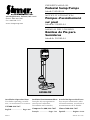
OWNER’S MANUAL
Pedestal Sump Pumps
Model 5020B-04
NOTICE D’UTILISATION
Pompes d’assèchement
sur pied
Modèle 5020B-04
MANUAL DEL USUARIO
Bombas de Pie para
Sumideros
Modelo 5020B-04
Installation/Operation/Parts
For further operating, installa-
tion, or maintenance assistance:
Call 800-468-7867
English ...................... Pages 2-6
Installation/Fonctionnement/Pièces
Pour plus de renseignements
concernant l’utilisation,
l’installation ou l’entretien,
Composer le
(800) 468-7867
Français ................ Pages 7-11
Instalación/Operación/Piezas
Para mayor información sobre
el funcionamiento, instalación o
mantenimiento de la bomba:
Llame al 800-468-7867
Español ............... Paginas 12-16
©2012 SIM722 (07/11/12)
5967 0309
293 Wright Street, Delavan, WI 53115
Phone: 800-468-7867
Fax: 800-390-5351
www.simerpump.com
5020B-04

Warranty 2
Retain Original Receipt For Warranty Eligibility
Limited Warranty
This Limited Warranty is effective June 1, 2011 and replaces all undated warranties and warranties dated before June 1, 2011.
SIMER warrants to the original consumer purchaser (“Purchaser” or “You”) that its products are free from defects in material and
workmanship for a period of twelve (12) months from the date of the original consumer purchase. If, within twelve (12) months
from the original consumer purchase, any such product shall prove to be defective, it shall be repaired or replaced at SIMER’s
option, subject to the terms and conditions set forth herein. Note that this limited warranty applies to manufacturing defects
only and not to ordinary wear and tear. All mechanical devices need periodic parts and service to perform well. This limited
warranty does not cover repair when normal use has exhausted the life of a part or the equipment.
The original purchase receipt and product warranty information label are required to determine warranty eligibility. Eligibility
is based on purchase date of original product – not the date of replacement under warranty. The warranty is limited to repair
or replacement of original purchased product only, not replacement product (i.e. one warranty replacement allowed per
purchase). Purchaser pays all removal, installation, labor, shipping, and incidental charges.
For parts or troubleshooting assistance, DO NOT return product to your retail store. Contact SIMER Customer Service
at 800-468-7867.
Claims made under this warranty shall be made by returning the product (except sewage pumps, see below) to the retail outlet
where it was purchased or to the factory immediately after the discovery of any alleged defect. SIMER will subsequently take
corrective action as promptly as reasonably possible. No requests for service will be accepted if received more than 30 days
after the warranty expires. Warranty is not transferable and does not apply to products used in commercial/rentalapplications.
Sewage Pumps
DO NOT return a sewage pump (that has been installed) to your retail store. Contact SIMER Customer Service. Sewage pumps
that have seen service and been removed carry a contamination hazard with them.
If your sewage pump has failed:
• Wearrubbergloveswhenhandlingthepump;
• Forwarrantypurposes,returnthepump’scordtagandoriginalreceiptofpurchasetotheretailstore;
• Disposeofthepumpaccordingtolocaldisposalordinances.
Exceptions to the Twelve (12) Month Limited Warranty
Product Warranty Period
BW85P, M40P 90 days
2115, 2300, 2310, 2330, 2943, 2955, 2956, 2957, A5500 2 Years
4” Submersible Well Pumps, 2945, 2958, 2975PC, 3075SS, 3963, 3984, 3995 3 Years
Pre-Charged Pressure Tanks, 3985, 3986, 3988, 3989, 5910, 5950, 5955, 5965, 5975 5 Years
General Terms and Conditions; Limitation of Remedies
You must pay all labor and shipping charges necessary to replace product covered by this warranty. This warranty does not
applytothefollowing:(1)actsofGod;(2)productswhich,inSIMER’ssolejudgement,havebeensubjecttonegligence,abuse,
accident,misapplication,tampering,oralteration;(3)failuresduetoimproperinstallation,operation,maintenanceorstorage;
(4)atypicalorunapprovedapplication,useorservice;(5)failurescausedbycorrosion,rustorotherforeignmaterialsinthe
system, or operation at pressures in excess of recommended maximums.
This warranty sets forth SIMER’s sole obligation and purchaser’s exclusive remedy for defective products.
SIMER SHALL NOT BE LIABLE FOR ANY CONSEQUENTIAL, INCIDENTAL, OR CONTINGENT DAMAGES WHATSOEVER.
THE FOREGOING WARRANTIES ARE EXCLUSIVE AND IN LIEU OF ALL OTHER EXPRESS AND IMPLIED WARRANTIES,
INCLUDING BUT NOT LIMITED TO THE IMPLIED WARRANTIES OF MERCHANTABILITY AND FITNESS FOR A PARTICULAR
PURPOSE. THE FOREGOING WARRANTIES SHALL NOT EXTEND BEYOND THE DURATION PROVIDEDHEREIN.
Some states do not allow the exclusion or limitation of incidental or consequential damages or limitations on how long an
implied warranty lasts, so the above limitations or exclusions may not apply to You. This warranty gives You specific legal
rights and You may also have other rights which vary from state to state.
SIMER • 293 Wright Street • Delavan, WI U.S.A. 53115
Phone: 800-468-7867 • Fax: 800-390-5351 • www.simerpump.com

Safety 3
For parts or assistance, call Simer Customer Service at 800-468-7867
Im portant Safety
Instructions
SAVE THESE INSTRUCTIONS - This manual
contains important instructions that should be
followed during installation, operation, and
maintenance of the product.
This is the safety alert symbol. When you see
this symbol on your pump or in this manual, look
for one of the following signal words and be alert to
the potential for personal injury!
indicates a hazard which, if not
avoided, will result in death or serious injury.
indicates a hazard which, if not
avoided, could result in death or serious injury.
indicates a hazard which, if not
avoided, could result in minor or moderate injury.
NOTICE addresses practices not related to
personalinjury.
Carefully read and follow all safety instructions in
this manual and on pump.
Keep safety labels in good condition. Replace
missing or damaged safety labels.
California Proposition 65 Warning
This product contains chemicals
known to the State of California to cause cancer or
birth defects or other reproductive harm.
NOTICE This unit is not designed for applications
involving salt water or brine! Use with salt water or
brine will void warranty.
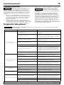
Specifications
Power supply required .......................115V, 60 HZ.
Horsepower ........................................................ 1/3
Motor duty ............................................ Intermittent
Liquid Temp. Range .............. 32°F to 70°F(0°-21°C)
Individual Branch Circuit Required GFCI Class A 15
Amps
Motor full load (maximum) ...................... 3.5 Amps
Discharge: ............................................1-1/4” FNPT
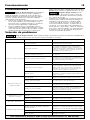
Performance
1. Know the pump application, limitations, and
potential hazards.
Risk of explosion. Do not ground
to a gas supply line. Do not use in explosive
atmospheres. Pump water only with this pump.
Failure to follow this warning can result in personal
injury and/or property damage.
2. Disconnect power before servicing.
3. Release all pressure within system before
servicing any component.
4. Drain all water from system before servicing.
Risk of flooding. Can cause personal
injury and/or property damage. If a flexible discharge
hose is used, pump may move when motor starts. If
it moves far enough so that switch hits side of sump,
switch may stick and prevent pump from starting.
Make sure pump is secured so it cannot move around
in sump.
5. Secure discharge line before starting pump. An
unsecured discharge line will whip, possibly
causing personal injury and/or property damage.
6.
Check hoses for weak or worn condition before
each use, making certain all connections are secure.
7. Inspect sump, pump and system components
monthly. Keep free of debris and foreign objects.
Perform routine maintenance as required.
Risk of fire. Do not store or rest
objects on or near motor or switch linkage.
Keep all flammable objects or liquids away
from motor.
8.
Provide means of pressure relief for pumps whose
discharge line can be shut-off or obstructed.
9. Personal Safety:
a. Wear safety glasses at all times when
working with pumps.
b. Keep work area clean, uncluttered and
properly lighted – replace all unused tools
and equipment.
c.
Keep visitors at a safe distance from work area.
d.
Make workshop child-proof – with padlocks,
master switches, and by removing starter keys.
10. When wiring an electrically driven pump,
follow all electrical and safety codes, as well as
most recent National Electrical Code (NEC) and
Occupational Safety and Health Act (OSHA).
11. This equipment is only for use on 115 volt
(single phase) and is equipped with an
approved 3-conductor cord and 3-prong,
grounding-type plug.
Risk of electric shock. Can shock,
burn or kill. Be certain that it is connected to
properly grounded, grounding-type receptacle.
Never connect green (or green and yellow) wire in
cord to a live terminal!
Where a 2-prong wall receptacle is encountered, it
must be replaced with properly grounded 3-prong
receptacle installed in accordance with the National
Electrical Code and local codes and ordinances.
12. All wiring should be performed by a
qualifiedelectrician.
13. Make certain that power source conforms to
requirements of your equipment.
14. Protect electrical cord from sharp objects, hot
surfaces, oil, and chemicals. Avoid kinking
cord. Replace or repair damaged or worn
cordsimmediately.
15.
Do not touch an operating motor. Modern motors
are designed to operate at high temperatures.
16. Do not handle pump or pump motor with
wet hands or when standing on wet or damp
surface, or in water.
Risk of electric shock. Can shock,
burn or kill. If your basement has water or moisture
on floor, do not walk on wet area until all power
has been turned off. If shut-off box is in basement,
call electric company to shut-off service to house, or
call local fire department for instructions. Remove
pump and repair or replace. Failure to follow this
warning can result in fatal electrical shock.
Risk of explosion. Do not ground
to a gas supply line.Do not use in hazardous or
explosive locations.
GPH (LPH) At Total Feet (M)
5 Ft. (1.52) 10 Ft. (3.05) 15 Ft (4.57) 20 Ft (6.09)
3000 (11 355L) 2460 (9 312L) 1620 (6 131L) 0 (0L)

Installation • Operation 4
For parts or assistance, call Simer Customer Service at 800-468-7867
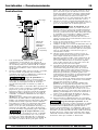
Installation
1. This unit can be installed in sump pit with
minimum diameter of 12”(30cm) and depth
of 12” (30cm). Sump pit may be constructed
of tile, concrete, steel or plastic. Check local
codes for approved materials.
2. Install pump on solid, level foundation, as near
as possible to center of sump pit. Do not hang
pump from discharge pipe or power cord.
Risk of burns. Pump must be level
(column must be vertical) when operating. If
motor is tilted, internal start/run switch may
overheat and damage motor.
3. Pump should not be installed on clay, earth or
sand surfaces. Clean sump pit of small stones
and gravel which could clog the pump. Keep
pump inlet screen clear.
4. Thread discharge pipe into pump body
carefully to avoid stripping or crossing threads.
NOTICE Do not use ordinary pipe joint
compound on plastic pipe or pump. Pipe joint
compound can attack plastics and damage pump.
5. To reduce motor noise and vibrations, a short
length of rubber hose (1-5/8”(41mm) I.D., e.g.
radiator hose) can be connected into discharge
line near pump using suitable clamps.
Risk of electric shock. Can shock,
burn or kill. Pump is designed for 115V., 60
HZ operation and requires an individual branch
circuit of 15 amperes capacity. It is supplied
with a 3-wire cord set with grounding-type plug
for use in a 3-wire, grounded outlet. Do not
cut off the round grounding prong. For safety,
outlet must always be electrically grounded to
a suitable electrical ground such as a grounded
water pipe or a properly grounded metallic
raceway or ground wire system.
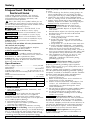
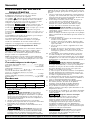
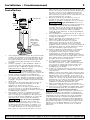
6. Locate Float Rod Guide (Key No. 6) about 6”
(16cm) below motor. Clamp guide to column
with screw provided.
Risk of flooding. Can cause
personal injury and/or property damage. Be
sure that guide is securely clamped so that float
rod is vertical and can move up and down
freely. If float is angled or binds, pump may not
start, allowing flooding to occur.
7. Screw float onto threaded end of rod.
Threads on rod will cut threads into corrosion
resistantafloat.
8. Insert plain end of float rod up through eye of
rod guide.
9. Slide one rod stop on float rod before passing
rod through eye of pump switch. Slide 2nd rod
stop on rod after passing through eye of switch.
Position 2nd rod stop flush with top of rod.
10. Position lower rod stop to within 8”(20cm) of
switch lever arm. With lower rod stop in this
position, pump will automatically cycle at
approximately 2-1/2”(6cm) off and 10-12”(25-
30cm) on. For faster cycling, move lower rod
stop closer to switch lever arm.
11. If pump discharge line is exposed to outside
subfreezing atmosphere, then portion of
line exposed must be installed so any water
remaining in pipe will drain to outfall by
gravity. Failure to do this can cause water
trapped in discharge to freeze which could
result in damage to pump.
12. Install an in-line check valve to prevent flow
backwards through pump after pump shuts off.
NOTICE Simer check valves are equipped
with an air bleed hole to prevent airlocking the
pump. If using a check valve that is not a Simer
valve, drill a 1/8” (3.2mm) hole in discharge
pipe just above pump body but below the
check valve to prevent air locks.
13. After all piping and controls have been
installed, unit is ready for operation.
14. Run pump through one cycle to check float
switch operation.
Risk of sudden starts. Can
cause electrical shock and personal
injury.
The pump motor is equipped with
automatic resetting thermal protector and
may restart unexpectedly. Protector tripping
is an indication of motor overloading as a
result of operating pump at low heads (low
discharge restriction), excessively high or low
voltage, inadequate wiring, incorrect motor
connections, or a defective motor.
5098 0705
Discharge
About 6"
About 8"
Check
Valve
(Purchase
Separately)

Troubleshooting
Operation 5
For parts or assistance, call Simer Customer Service at 800-468-7867
Risk of electric shock. Can shock, burn or kill. Unplug pump from power receptacle
before working on pump.
Operation
Risk of electric shock. Can shock,
burn or kill. Do not touch sump pump, pump
motor, water, or discharge piping when pump is
connected to electrical power. Always disconnect
pump cord (power) before handling.
1. Plug this unit into a 115V outlet, on an indi-
vidual branch circuit, with a Class A, 15 amp
GFCI (Ground Fault Circuit Interrupter). Consult
your local electrician for information and avail-
ability.
2. Fill sump pit with water, pump will start auto-
matically when lower rod stop actuates switch
lever arm. When upper rod stop actuates
switch lever arm, pump will stop.
NOTICE Do not allow pump to run dry.
Risk of electric shock. Can shock,
burn or kill. Before attempting to service,
always disconnect power from unit.
3. The motor is equipped with an automatic reset
thermal protector to protect unit from overheat-
ing. When motor has cooled sufficiently, switch
will reset automatically and restart motor.
Repeated tripping could be caused by low volt-
age, long extension cords, clogged impeller,
very low head or lift, etc. Cycling of protector
will cause eventual motor burnout.
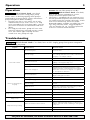
Symptom Possible Cause(s) Corrective Action
Motor will not Run
No electrical power
Check fuse, circuit breaker, power cord and and
electrical outlet.
Low line voltage
If voltage wiring under recommended minimum, check
size of wiring from main source. If OK, contact Electric
Company or local Hydro cuthority.
Faulty automatic switch Operate switch manually and replace if inoperative.
Float or float rod stuck
Check to see float is not rubbing sump wall or float rod
rubbing or stuck against sump cover.
Watterlogged float Replace float if filled with water.
Motor overload tripped
If pump has been running and stops before sump is
emptied, automatic overload may have been tripped.
Check inlet screen to be sure impeller is not jammed. If
so, free impeller of obstruction.
Electrical malfunction
Check power cord, automatic switch and motor.
Replace faulty parts as needed.
Motor runs but pump will
not pump
Inlet clogged Check inlet and clean if needed.
Discharge line plugged Clear discharge line and check valve for obstruction.
Low line voltage
Refer to Corrective Action on low voltage in above
section.
Pump airlocked
Drill a 1/8” (3.2mm) hole in discharge pipe just above
pump body but below the check valve.
Broken impeller or shaft Replace impeller or shaft as needed.
Pump starts and stops too often
Improper positioning of float rod stop Lower float rod stop.
Faulty automatic switch Replace automatic switch.
Pump is noisy
Improper installation Refer to No. 5 in Installtion Instructions
Noisy motor Replace pump.
Pump will not stop running
Debris around float or float rod stuck
Remove debris from sump. Check to see float is not
rubbing sump wall or float rod rubbing or stuck against
sump cover.
Faulty automatic switch Replace switch.
Motor defective Replace pump.

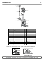
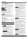
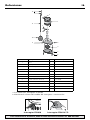
Repair Parts 6
For parts or assistance, call Simer Customer Service at 800-468-7867
5099 0705
1
2
3
4
5
6
7
8
9
10
11
12
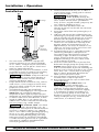
* If motor fails, replace entire pump. † Select switch model number below.
Switch FP0020
Switch FP0018-7D
Ref Description Qty. 5020B-04
1 Motor 1 *
2 Switch 1
†
3 Volute (Pump Body) 1 PS1-25P
4 Impeller 1 PS5-269P
5 Base Plate 1 PS4-17P
6 Screws (Base Plate) 8 U30-934ZP
7 Float Rod Guide 1 RP0005249
8 Screw (Guide Rod) 1 U30-929ZP
9 Screw (Base) 1 SC004-116
10 Float 1 FT0013-63
11 Float Rod 1 RP005168S
12 Float Stop 2 RP0005248
Page is loading ...
Page is loading ...
Page is loading ...
Page is loading ...
Page is loading ...
Page is loading ...
Page is loading ...
Page is loading ...
Page is loading ...
Page is loading ...
-
 1
1
-
 2
2
-
 3
3
-
 4
4
-
 5
5
-
 6
6
-
 7
7
-
 8
8
-
 9
9
-
 10
10
-
 11
11
-
 12
12
-
 13
13
-
 14
14
-
 15
15
-
 16
16


Simer 520B-04 Pedestal Sump Pumps Owner's manual
- Category
- Water pumps
- Type
- Owner's manual
Ask a question and I''ll find the answer in the document
Finding information in a document is now easier with AI
in other languages
Related papers
Other documents
-
Simer Pumps 5020B-04 User manual
-
Pentair 3995 Owner's manual
-
Pentair 2975PC Owner's manual
-
-
Simer Pumps 2945 User manual
-
-
-
Pentair BW85 Series Owner's manual
-
-