Intel NetportExpress 10/100 User manual
- Category
- Network switches
- Type
- User manual
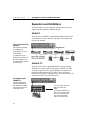
This manual is also suitable for

Intel Express 10/100
Fast Ethernet Switch
User Guide
Part No. 663096-001

First edition December 1996
Copyright © 1996, Intel Corporation. All rights reserved.
Intel Corporation, 5200 NE Elam Young Parkway, Hillsboro, OR 97124-6497
Intel Corporation assumes no responsibility for errors or omissions in this manual. Nor does Intel make any commitment to
update the information contained herein.
* Other product and corporate names may be trademarks of other companies and are used only for explanation and to the
owners’ benefit, without intent to infringe.

iii
Contents
Quick Start 1
Chapter 1 Hardware Installation and Network Topology 3
Overview .......................................................................................................................................... 3
Installation and Setup ....................................................................................................................... 4
Using the Switch............................................................................................................................... 5
Port status LEDs ........................................................................................................................ 5
Management status LEDs .......................................................................................................... 6
Cabling Requirements....................................................................................................................... 7
UTP requirements ...................................................................................................................... 7
Fiber optic requirements ............................................................................................................ 7
Straight-through vs. crossover cables ......................................................................................... 8
Typical Configurations ................................................................................................................... 10
Configuring the mixed 10 and 100 Mbps workgroup environment ........................................... 10
Configuring the Wide Area Network (WAN) or multi-floor environment ................................ 12
Repeater count limitations ....................................................................................................... 14
Chapter 2 Configuring and Managing the Switch 15
Accessing the Console Manager ..................................................................................................... 16
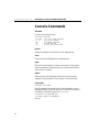
Using the Console Manager ............................................................................................................ 17
Entering commands ................................................................................................................. 17
Console Manager command groups.......................................................................................... 19
Sample Console Manager Session................................................................................................... 20
Configuring the SNMP agent for IP ......................................................................................... 21
Configuring a port for full duplex ............................................................................................ 22
Creating Virtual LANs (VLANs) ............................................................................................. 23
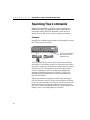
Monitoring traffic .................................................................................................................... 25
Chapter 3 Console Command Reference 31
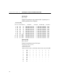
Console Command-line Summary................................................................................................... 32
Console Commands ........................................................................................................................ 38
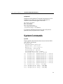
System Commands ......................................................................................................................... 39
IP Commands ................................................................................................................................. 43
IP configuration ....................................................................................................................... 43
Ping Commands ....................................................................................................................... 46
Address Resolution Protocol (ARP) Commands ....................................................................... 47

iv
CONTENTS
Intel Express 10/100 Fast Ethernet Switch
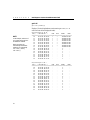
SNMP Commands .......................................................................................................................... 48
SNMP community strings ........................................................................................................ 48
SNMP trap message commands ............................................................................................... 49
Switching Database Commands ...................................................................................................... 50
Database control commands..................................................................................................... 51
Custom filtering ....................................................................................................................... 54
VLAN Commands .......................................................................................................................... 56
Spanning Tree Commands .............................................................................................................. 60
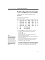
Port Configuration Commands........................................................................................................ 65
Statistics Commands....................................................................................................................... 66
Chapter 4 Troubleshooting 71
General Problems ........................................................................................................................... 72
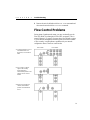
Flow Control Problems ................................................................................................................... 73
Appendix A Technical Information 75
Default Configuration ..................................................................................................................... 75
Specifications ................................................................................................................................. 77
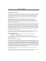
SNMP and MIB Support ................................................................................................................. 80
Limited Hardware Warranty ........................................................................................................... 81
Index 85
Intel Automated Customer Support Inside back cover

1
Rubber feet for shelf or table placement.
Brackets and screws for standard
19-inch equipment rack placement.
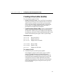
Quick Start
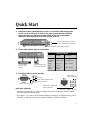
1. Install the Express 10/100 Switch in a rack or on a shelf or table and plug the
cord in. If you’re in Europe or Asia, or any other country that has a 220-volt
electrical system, set the power supply switch to 230 (115 is the default).
Otherwise, leave the switch set to 115. Turn the power on.
2. Connect the network devices to the switch.
3. Check the LEDs for power and links.
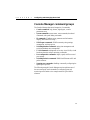
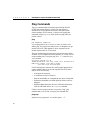
Next steps (Optional)
• Continue to the next page if you want to configure the switch to work with an SNMP-compliant
Network Management System (NMS).
• See Chapter 2 if you want to use the Console Manager to change port configurations (set a port for
full duplex or manually set the speed), assign an IP address, or check port statistics.
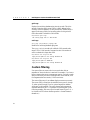
Crossover cables
to hubs or other
switches.
Straight-through cables
to servers/workstations.
Blinks every two seconds.
Lights briefly while the switch
performs self-tests.
Always on.
Lights when a 100BASE-TX
device is attached.
Lights when a
device is attached.
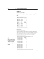
Cabling Guidelines
at 10 Mbps at 100 Mbps
Server/ CAT 3, 4, or 5 CAT 5
Workstation straight-through straight-through
to Switch
Hub to CAT 3, 4, or 5 CAT 5 crossover
Switch crossover
Switch to CAT 3, 4, or 5 CAT 5 crossover
Switch crossover

2
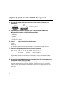
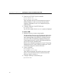
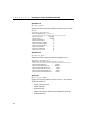
(Optional) Quick Start for SNMP Management
4. Use the null-modem cable to connect the Console port to a COM port on a
workstation.
5. Open a terminal emulation program (such as HyperTerminal in Microsoft
Windows* 95). Use these communication parameters:
• 9600 baud
• 8 data bits
• No parity
• 1 stop bit
• Xon/Xoff flow control
6. Press E and log into the Console Manager:
Login:
password:
By default, no password or user name is assigned. If you enter one, it’s saved upon reset.
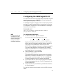
7. Set the IP configuration using the set-ip-conf command:
set-ip-conf 192.1.1.64 255.255.255.0 192.1.1.255
E
Replace these addresses with the numbers for your network. Specify the IP address, netmask
(subnet mask), and broadcast address (default gateway), in that order.
8. Download the Intel MIB (Management Information Base) file from an Intel online
service and compile it into your NMS.
The MIB filename is SWCH2MIB.EXE. You can find the file on Intel’s Customer Support web
site (http://support.intel.com) or the Intel BBS (Host: ftp.intel.com, Directory: pub/support/
enduser_reseller). See your NMS documentation for instructions on compiling the MIB for a
new device.
A null-modem cable is
provided with the switch.
IP address netmask broadcast address

3
Hardware Installation
and Network
Topology
Overview
The Intel Express 10/100 Fast Ethernet Switch features eight auto-
negotiating 10BASE-T/100BASE-TX ports. Each port supports an
Ethernet (10 Mbps) or Fast Ethernet (100 Mbps) segment. The switch
also has two slots for optional two-port media adapters (such as
100BASE-TX or 100BASE-FX).
The switch also has a built-in SNMP (Simple Network Management
Protocol) agent and can be monitored and controlled through any
SNMP-compliant Network Management System (NMS), such as Intel
LANDesk
®
Network Manager. See page 21 for information on using
the switch with an SNMP NMS and getting the switch’s MIB.
1

4
CHAPTER 1
Intel Express 10/100 Fast Ethernet Switch
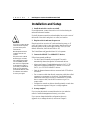
Installation and Setup
1 Install the switch in a rack or on a shelf.
For rack placement, connect the switch to a 19-inch rack using the
enclosed rack mount brackets.
For shelf placement, attach the enclosed rubber feet to each corner of
the bottom of the switch and place it on a flat, level surface.
2 Plug the switch in and turn the power on.
Plug the switch into an active AC outlet and turn the power on. If
you’re in Europe or Asia, or any other country that has a 220-volt
electrical system, set the power supply switch to 230 (115 is the
default). Otherwise, leave the switch set to 115.
The United States and Japan both have 110 volt systems.
3 Connect the 10BASE-T or 100BASE-TX devices.
Follow these general guidelines:
• You don’t need to manually set the speed. The switch
automatically detects the speed of the connected devices.
• Always use Category 5 unshielded twisted-pair (CAT 5 UTP)
cable when connecting 100BASE-TX devices. You can use
CAT 3, 4, or 5 UTP for 10BASE-T devices.
• Limit the distance between devices connected with UTP cable to
100 meters.
• Use a crossover cable when directly connecting a hub (also called
a repeater or concentrator) to the switch. Use straight-through
cables when connecting to servers or workstations. If you don’t
have a crossover cable, use the MDI connector on port 1 to
connect a hub.
• Configure the network so devices that talk primarily to each other
are on the same segment. Each port is a single segment.
4 Is setup complete?
If you’re using the switch as a stand-alone device (not under the
control of network management software), you’re done.
If you want to change the default configuration (shown in
Appendix A) or manage the switch, continue to Chapter 2.
WARNING
If you’re in a country that has
a 220-volt electrical system,
you must set the power
switch to 230.
Most European and Asian
countries have 220-volt
systems.
The power cord is a North
American type, UL-listed/
CSA-certified power supply
cord. Immediately discard
this cord if it is inappropriate
for the electrical system of
your country, and obtain the
proper cord as required by
your national electrical codes
or ordinances and certified
for use in your region.

5
Hardware Installation and Network Topology
CHAPTER 1
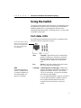
Using the Switch
The switch requires minimal user intervention. It automatically learns
the addresses of new devices as you connect them, and will relearn
addresses dynamically if you reconfigure the network. It also
automatically detects the speed of connected devices. You don’t need
to manually set the speed.
Port status LEDs
Port LEDs provide information about each port’s configuration and
the status of devices connected to the ports.
Xmt Transmit. Lights when the switch is transmitting
packets from this port to another port. Normally
blinks at regular intervals, even if no devices are
connected, while it updates the internal SNMP
agent.
Rcv Receive. Lights when packets are received on this
port, even if they are not forwarded.
Coll/Fdpx Collision (default) or Full Duplex. Blinks when
collisions are detected. Collisions are normal in an
Ethernet environment. However, if the collision
LED is on continuously, you may have a problem
with a device on the segment.
If you’ve enabled full duplex on the port, the LED is
on solid. When full duplex is enabled, collisions
aren’t possible because packets are sent and
received on their own wire pair, so they can’t
collide.
Ports on the switch are wired
MDI-X for connection to MDI
ports using a straight-through
UTP cable. See page 8 for
more information.
NOTE
The default configuration of
all ports is half-duplex mode.
To change to full duplex, use
the Console Manager. See
page 22 for instructions.

6
CHAPTER 1
Intel Express 10/100 Fast Ethernet Switch
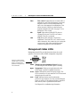
Flow Flow control. Lights whenever too much traffic is
entering on a port. When this happens, the switch’s
buffers fill and it’s forced to back pressure the
traffic out to the segment for retransmission. This
allows the switch’s buffers to clear before the
segment retransmits the traffic. See page 73 for a
description of flow control.
100 Speed. Lights when a 100BASE-TX device is
connected to the port. The LED is off when a
10BASE-T device is connected.
Link Link. When solid, indicates a connection is
established. If the Link LED is off, check for loose
cable connections. Also, make sure you’re using the
correct type of cable, either straight-through or
crossover. See page 8 for more information.
Management status LEDs
Management status LEDs provide information about the overall
operation of the switch and its SNMP management components.
SNMP Simple Network Management Protocol. Always
on, indicating the built-in SNMP agent is working.
Mgmt Management. Blinks on at regular intervals as the
SNMP agent is polled for updated information.
Power Power. Indicates the status of the power supply. The
LED is normally on. It may remain off for a few seconds
during the power-on self-test.
Fault Fault. Indicates that the switch has detected a
problem. It may remain on for a few seconds during the
power-on self-test. If this indicator blinks or remains lit
after self-test, there’s a problem with the switch.
See Chapter 4 for troubleshooting information.
Use these communications
settings when accessing the
built-in Console Manager
application. See page 16 for
more information.

7
Hardware Installation and Network Topology
CHAPTER 1
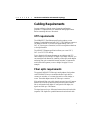
Cabling Requirements
Incorrect cabling is often the cause of network configuration
problems. It’s important that you understand cabling requirements
before connecting devices to the switch.
UTP requirements
The 100BASE-TX Fast Ethernet specification requires you use
Category 5 unshielded twisted-pair (CAT 5 UTP) cabling to operate at
100 Mbps per second. If you use lower grade cabling (CAT 3 or
CAT 4), you may get a connection, but will soon experience data loss
or slow performance.
The 10BASE-T Ethernet specification allows you to use CAT 3,
CAT 4, or CAT 5 UTP cabling.
You’re limited to 100 meters between any two devices with UTP
cable whether you’re running at 10 Mbps or 100 Mbps. However, you
can extend the total diameter by installing a fiber optic media adapter
and using fiber optic connections between switches, or between the
switch and a hub (repeater), router or bridge. See page 12 for an
example.
Fiber optic requirements
The optional 100BASE-FX fiber optic media adapter (Intel product
code ES101MAFX) lets you use multimode fiber optic cable to
connect two switches, or to connect the switch to a hub, bridge, or
router. The media adapter uses an SC fiber optic connector.
With multimode fiber optic cable, signals can travel up to 412 meters
between two switches or between the switch and a router when the
link is configured at half duplex. If configured at full duplex, the
signal can travel up to 2 kilometers.
The signal can travel up to 160 meters between the switch and a hub
(repeater). Full duplex isn’t possible between the switch and a hub.

8
CHAPTER 1
Intel Express 10/100 Fast Ethernet Switch
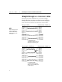
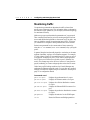
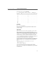
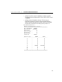
Straight-through vs. crossover cables
Ports on the switch are wired MDI-X so you can use a straight-
through cable when connecting to a workstation or server (adapter
cards are wired MDI). For direct connection to another MDI-X port
(most hubs and some switches), you must use a crossover cable.
NIC RJ-45 (MDI) Switch/Hub RJ-45 (MDI-X)
Switch/Hub RJ-45 (MDI-X) Switch/Hub RJ-45 (MDI-X)
A straight-through
(standard) cable connects
MDI ports to MDI-X ports.
A crossover cable
connects MDI-X ports to
MDI-X ports (or MDI ports
to MDI ports).
NOTE
When making your own
cables, wires 1 and 2
must be a twisted pair
and 3 and 6 must be a
twisted pair.

9
Hardware Installation and Network Topology
CHAPTER 1
Determining which cable to use
Different switch and repeater manufacturers implement their port
configurations differently. The following guidelines are based on the
Express 10/100 Switch, the Intel Express 100BASE-TX Stackable
Hub (repeater) and the EtherExpress™ family of adapters (server or
workstation). These apply to the majority of switches and hubs and all
servers or workstations:
For this connection Use this cable
Switch to repeater Crossover
Switch to server or workstation Straight-through
Switch to switch Crossover
Repeater to server or workstation Straight-through
Port 1 on the switch has both an MDI and MDI-X connector. If you’re
not seeing a link on a port, try plugging into each of the port 1
connectors.

10
CHAPTER 1
Intel Express 10/100 Fast Ethernet Switch
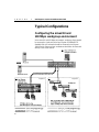
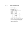
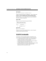
Typical Configurations
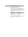
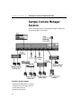
Configuring the mixed 10 and
100 Mbps workgroup environment
In the mixed 10 and 100 Mbps environment, workgroup clients should
be connected to a hubs such as the Intel Express 10/100BASE-TX
Stackable Hub. All hub stacks should be connected to the Express
10/100 Switch. Servers or busy workstations should also be connected
directly to the 10/100 Switch.
Segment 2
Segment 1

11
Hardware Installation and Network Topology
CHAPTER 1
Configuration guidelines:
Servers or workstations: Configure servers or workstations
directly connected to the switch for full duplex. Since the traffic is
two-way traffic, you’ll see a performance increase with a full
duplex configuration. See page 22 for instructions on configuring
full duplex.
Security considerations: If you have concerns about server
access or other security issues, configure security virtual LANs
(SVLANs) to prevent segments (ports) from accessing other ports.
In the example on the previous page, you may want to prevent
workstations on the 10 Mbps hub on port 4 from accessing the file
server on port 2. See page 23 for more information on configuring
SVLANs.
100 Mbps or 10 Mbps hubs: Leave hubs (repeaters) at half
duplex with flow control enabled. Since hubs broadcast traffic
among all ports and full duplex requires a point-to-point
connection, you can’t configure a 10 or 100 Mbps hub for full
duplex.

12
CHAPTER 1
Intel Express 10/100 Fast Ethernet Switch
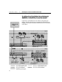
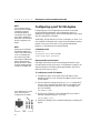
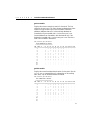
Configuring the Wide Area Network
(WAN) or multi-floor environment
Connections to the backbone are most effective using fiber optic
cabling, especially when devices are separated by multiple floors or
buildings. This extends the distance between devices to 2 kilometers
at full duplex.

13
Hardware Installation and Network Topology
CHAPTER 1
Configuration guidelines:
Fiber optic connections to switches or routers: Use multi-mode
fiber to connect to a router or another switch. You must purchase
a 100BASE-FX expansion module separately (Intel order code
ES101MAFX). Each module comes with two ports.
If the switch or router is capable of full duplex, the maximum
cable length between the two devices is 2 kilometers. At half
duplex the maximum is 412 meters.
Two-port 100BASE-TX expansion are also available (Intel order
code ES101MATX).
Full duplex and flow control between Express 10/100 switches:
The only time you can configure full duplex and flow control
simultaneously is between two Express 10/100 switches. Special
information is added to packets between switches to accomplish
this. This works with both fiber optic and CAT 5 cabling.
Fiber optic connections to repeaters: Since repeaters aren’t
capable of full duplex mode operation, you’re restricted to 160
meters of fiber optic cable between the Express Switch and a
repeater.
Multi-workgroup server configuration: Always put servers
accessed by multiple workgroups off of the switch. Because the
server has a point-to-point connection, you can configure it for
full duplex and increase the bandwidth of the connection. Note
that the adapter in the server must be capable of full duplex.
Network administrator’s workstation: Connect the
administrator’s workstation directly to the switch. This reduces
the risk of the administrator getting dropped off the network and
allows the administrator to get network information faster.
Local workgroup server configuration: Always connect servers
accessed by local workgroups to a hub, not to the switch. This
reduces the amount of traffic passing through the switch and
improves the performance for all workgroups connected to it.
However, if more than one workgroup accesses a server, connect
the server directly to the switch.

14
CHAPTER 1
Intel Express 10/100 Fast Ethernet Switch
One repeater hop for
100BASE-TX
Only one repeater hop is
allowed for 100BASE-TX.
Also, the distance between
the node and switch can’t
exceed 200 meters.
You can’t daisy-chain 100
Mbps hubs with UTP
cable.
For Express 100BASE-TX
hubs, use cascade cables.
For other 100 Mbps hubs,
see the documentation
that came with the hub.
Repeater count limitations
The switch doesn’t count as a repeater. Each port on the switch can
support a full Fast Ethernet or Ethernet network.
10BASE-T
There can be four 10BASE-T repeaters/hubs between the switch and
any workstation or server. However, only three of the repeaters can
have devices attached.
100BASE-TX
There can be one class 1 repeater/hub between the switch and any
workstation or server (a stack of Intel Express 100BASE-TX Hubs
counts as a single hub). Also, the total diameter of a segment can’t
exceed 200 meters when using UTP cable. That is, the distance
between any two nodes on a segment (or the switch and a node on the
other side of a hub) can’t exceed 200 meters.
5-4-3-2-1 general rule for
10BASE-T
Five segments are allowed
Four repeater hops
Three repeaters can have
nodes attached
Two segments can’t be
populated and are links only
All of this makes One colli-
sion domain with a maximum
of 1024 stations.

15
2
Configuring and
Managing the Switch
You don’t need to read this chapter or Chapter 3 unless you want to
change the Express 10/100 Fast Ethernet Switch’s default
configuration (see Appendix A for a list of defaults) or intend to
manage the switch. The switch is ready to go simply by plugging it in
and turning the power on.
However, if you need to change the default configuration or manage
the switch, there are two ways:
• Use SNMP-compliant management software such as Intel
LANDesk Network Manager (not included).
• Use the Express 10/100 Switch’s internal Console Manager either
by directly connecting a serial cable or through Telnet.
To use SNMP management software or Telnet to the switch, you must
first connect to the switch using a serial cable and use the Console
Manager to assign an IP address.

16
CHAPTER 2
Intel Express 10/100 Fast Ethernet Switch
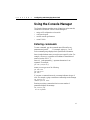
Accessing the Console
Manager
The Console Manager software is contained in the switch’s
nonvolatile RAM (NVRAM). You don’t need to install any software.
To access the Console Manager:
1 Use the null-modem cable (included with the switch) to connect a
workstation’s COM port to the Console port on the switch.
2 Open a terminal emulation program (such as HyperTerminal in
Windows 95).
3 Select the COM port and these communication parameters:
9600 baud, 8 data bits, no parity, 1 stop bit, Xon/Xoff flow control
(To set these parameters in HyperTerminal, choose Properties
from the File menu. Then click the Configure button.)
4 Press E. The login prompt appears:
Please Login
username:
password:
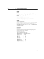
By default, no username or password is assigned. If you enter a
password, it becomes active only after you reset the switch or turn
off the power. If you want the password to take effect
immediately, use the
set-passwd command.
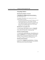
Accessing the Console Manager remotely
To access remotely through Telnet, first set the IP configuration of the
switch using the
set-ip-conf command through the Console port (see
page 21 for instructions). Then use Telnet to reach the switch.
All commands work as if a terminal were directly connected to the
Console port. Only one console session can be active at a time (either
local or remote). After the first Telnet session is established, other
Telnet connections are refused until the current session is closed.
NOTE
In HyperTerminal, you must
set flow control (unrelated to
the switch’s flow control
feature) to Xon/Xoff.
NOTE
For more information about
any of the commands used in
this chapter, see Chapter 3,
Console Command Refer-
ence.
Page is loading ...
Page is loading ...
Page is loading ...
Page is loading ...
Page is loading ...
Page is loading ...
Page is loading ...
Page is loading ...
Page is loading ...
Page is loading ...
Page is loading ...
Page is loading ...
Page is loading ...
Page is loading ...
Page is loading ...
Page is loading ...
Page is loading ...
Page is loading ...
Page is loading ...
Page is loading ...
Page is loading ...
Page is loading ...
Page is loading ...
Page is loading ...
Page is loading ...
Page is loading ...
Page is loading ...
Page is loading ...
Page is loading ...
Page is loading ...
Page is loading ...
Page is loading ...
Page is loading ...
Page is loading ...
Page is loading ...
Page is loading ...
Page is loading ...
Page is loading ...
Page is loading ...
Page is loading ...
Page is loading ...
Page is loading ...
Page is loading ...
Page is loading ...
Page is loading ...
Page is loading ...
Page is loading ...
Page is loading ...
Page is loading ...
Page is loading ...
Page is loading ...
Page is loading ...
Page is loading ...
Page is loading ...
Page is loading ...
Page is loading ...
Page is loading ...
Page is loading ...
Page is loading ...
Page is loading ...
Page is loading ...
Page is loading ...
Page is loading ...
Page is loading ...
Page is loading ...
Page is loading ...
Page is loading ...
Page is loading ...
Page is loading ...
Page is loading ...
Page is loading ...
Page is loading ...
Page is loading ...
-
 1
1
-
 2
2
-
 3
3
-
 4
4
-
 5
5
-
 6
6
-
 7
7
-
 8
8
-
 9
9
-
 10
10
-
 11
11
-
 12
12
-
 13
13
-
 14
14
-
 15
15
-
 16
16
-
 17
17
-
 18
18
-
 19
19
-
 20
20
-
 21
21
-
 22
22
-
 23
23
-
 24
24
-
 25
25
-
 26
26
-
 27
27
-
 28
28
-
 29
29
-
 30
30
-
 31
31
-
 32
32
-
 33
33
-
 34
34
-
 35
35
-
 36
36
-
 37
37
-
 38
38
-
 39
39
-
 40
40
-
 41
41
-
 42
42
-
 43
43
-
 44
44
-
 45
45
-
 46
46
-
 47
47
-
 48
48
-
 49
49
-
 50
50
-
 51
51
-
 52
52
-
 53
53
-
 54
54
-
 55
55
-
 56
56
-
 57
57
-
 58
58
-
 59
59
-
 60
60
-
 61
61
-
 62
62
-
 63
63
-
 64
64
-
 65
65
-
 66
66
-
 67
67
-
 68
68
-
 69
69
-
 70
70
-
 71
71
-
 72
72
-
 73
73
-
 74
74
-
 75
75
-
 76
76
-
 77
77
-
 78
78
-
 79
79
-
 80
80
-
 81
81
-
 82
82
-
 83
83
-
 84
84
-
 85
85
-
 86
86
-
 87
87
-
 88
88
-
 89
89
-
 90
90
-
 91
91
-
 92
92
-
 93
93


Intel NetportExpress 10/100 User manual
- Category
- Network switches
- Type
- User manual
- This manual is also suitable for
Ask a question and I''ll find the answer in the document
Finding information in a document is now easier with AI
Related papers
Other documents
-
MiLAN MIL-S3570 Installation guide
-
 Asante Technologies FriendlyNET FM2017 User manual
-
 Cabletron Systems SmartSTACK ELS100-24TXM User manual
-
KTI Networks KS-2240 User manual
-
MiLAN MIL-SM801 User manual
-
-
 Cabletron Systems SmartSTACK 100 ELS100-24TXG User manual
-
Enterasys Networks VH-8TX1MF User manual
-
SMC Networks SMC8950EM User manual
-
Edge-Core ES4625 Installation guide


