Page is loading ...

Service Manual
R-410A Models
Room Air Conditioners
2 0 1 1
Cool Only
Cool with Electric Heat
X-Star-ServMan (1-11)
115-Volt: XQ05M10
*
, XQ06M10
*
, XQ08M10
*
, XQ10M10
*
115-Volt: EQ08M11
*
*
Last character may vary.
M oney
Fa
n
Set H
r
.
Sto
p
St
a
rt
Tem pera
ture
Fa
n
Cool
On/
Cooler
W arm e
r
On
l
y S
p
eed Saver
®
P
o
wer
Tim
e
r O
p
e
r
ation

1
Table Of Contents
Important Safety Information .......................................................................................................................................... 2-4
Unit Identifi cation ............................................................................................................................................................... 5
Performance Data ............................................................................................................................................................. 6
Chassis Specifi cations ...................................................................................................................................................... 6
Installation Information/Sleeve Dimensions ...................................................................................................................... 6
Electrical Data ................................................................................................................................................................... 7
Before Operating the Unit ................................................................................................................................................. 8
For Best Cooling Performance and Energy Effi ciency ...................................................................................................... 8
How to Operate the XQ ..................................................................................................................................................... 9
How to Use the XQ Remote Control ............................................................................................................................... 10
How to Operate the EQ ................................................................................................................................................... 10
Electronic Control Sequence of Operation ...................................................................................................................... 11
Functional Component Defi nition .................................................................................................................................... 12
Components Testing .................................................................................................................................................. 13-16
Refrigeration Sequence of Operation ............................................................................................................................. 17
R-410A Sealed System Repair Considerations .............................................................................................................. 18
Sealed Refrigeration System Repairs ........................................................................................................................ 19-22
Compressor Checks ................................................................................................................................................... 23-24
Compressor Replacement .......................................................................................................................................... 25-26
Routine Maintenance ................................................................................................................................................. 27-28
Performance Test Data Sheet ......................................................................................................................................... 29
Troubleshooting ......................................................................................................................................................... 30-36
Wiring Diagrams ........................................................................................................................................................ 37-38
Instructions for using Cooling Load Estimate Form ........................................................................................................ 39
Cooling Load Estimate Form ........................................................................................................................................... 40
Heat Load Form ......................................................................................................................................................... 41-42
Warranty .......................................................................................................................................................................... 43
Technical Assistance ....................................................................................................................................................... 44

IMPORTANT SAFETY INFORMATION
The information contained in this manual is intended for use by a qualifi ed service technician who is familiar
with the safety procedures required for installation and repair, and who is equipped with the proper tools and
test instruments required to service this product.
Installation or repairs made by unqualifi ed persons can result in subjecting the unqualifi ed person making
such repairs as well as the persons being served by the equipment to hazards resulting in injury or electrical
shock which can be serious or even fatal.
Safety warnings have been placed throughout this manual to alert you to potential hazards that may be
encountered. If you install or perform service on equipment, it is your responsibility to read and obey these
warnings to guard against any bodily injury or property damage which may result to you or others.
PERSONAL INJURY OR DEATH HAZARDS
ELECTRICAL HAZARDS:
• Unplug and/or disconnect all electrical power to the unit before performing inspections,
maintenance, or service.
• Make sure to follow proper lockout/tag out procedures.
• Always work in the company of a qualifi ed assistant if possible.
• Capacitors, even when disconnected from the electrical power source, retain an electrical charge
potential capable of causing electric shock or electrocution.
• Handle, discharge, and test capacitors according to safe, established, standards, and approved
procedures.
• Extreme care, proper judgment, and safety procedures must be exercised if it becomes necessary
to test or troubleshoot equipment with the power on to the unit.
Your safety and the safety of others are very important.
We have provided many important safety messages in this manual and on your appliance. Always read
and obey all safety messages.
All safety messages will tell you what the potential hazard is, tell you how to reduce the chance of injury,
and tell you what will happen if the instructions are not followed.
This is a Safety Alert symbol.
This symbol alerts you to potential hazards that can kill or hurt you and others.
All safety messages will follow the safety alert symbol with the word “WARNING”
or “CAUTION”. These words mean:
You can be killed or seriously injured if you do not follow instructions.
You can receive minor or moderate injury if you do not follow instructions.
A message to alert you of potential property damage will have the
word “NOTICE”. Potential property damage can occur if instructions
are not followed.
WARNING
CAUTION
NOTICE
2

• Do not spray or pour water on the return air grille, discharge air grille, evaporator coil, control panel,
and sleeve on the room side of the air conditioning unit while cleaning.
• Electrical component malfunction caused by water could result in electric shock or other electrically
unsafe conditions when the power is restored and the unit is turned on, even after the exterior is dry.
• Never operate the A/C unit with wet hands.
• Use air conditioner on a single dedicated circuit within the specifi ed amperage rating.
• Use on a properly grounded outlet only.
• Do not remove ground prong of plug.
• Do not cut or modify the power supply cord.
• Do not use extension cords with the unit.
• Follow all safety precautions and use proper and adequate protective safety aids such as: gloves,
goggles, clothing, adequately insulated tools, and testing equipment etc.
• Failure to follow proper safety procedures and/or these warnings can result in serious injury or death.
REFRIGERATION SYSTEM HAZARDS:
• Use approved standard refrigerant recovering procedures and equipment to relieve pressure before
opening system for repair.
• Do not allow liquid refrigerant to contact skin. Direct contact with liquid refrigerant can result in minor
to moderate injury.
• Be extremely careful when using an oxy-acetylene torch. Direct contact with the torch’s fl ame or hot
surfaces can cause serious burns.
• Make sure to protect personal and surrounding property with fi re proof materials.
• Have a fi re extinguisher at hand while using a torch.
• Provide adequate ventilation to vent off toxic fumes, and work with a qualifi ed assistant whenever
possible.
• Always use a pressure regulator when using dry nitrogen to test the sealed refrigeration system for
leaks, fl ushing etc.
• Make sure to follow all safety precautions and to use proper protective safety aids such as: gloves,
safety glasses, clothing etc.
• Failure to follow proper safety procedures and/or these warnings can result in serious injury or death.
MECHANICAL HAZARDS:
• Extreme care, proper judgment and all safety procedures must be followed when testing,
troubleshooting, handling, or working around unit with moving and/or rotating parts.
• Be careful when, handling and working around exposed edges and corners of sleeve, chassis, and
other unit components especially the sharp fi ns of the indoor and outdoor coils.
• Use proper and adequate protective aids such as: gloves, clothing, safety glasses etc.
• Failure to follow proper safety procedures and/or these warnings can result in serious injury or death.
3

PROPERTY DAMAGE HAZARDS
FIRE DAMAGE HAZARDS:
• Read the Installation/Operation Manual for this air conditioning unit prior to operating.
• Use air conditioner on a single dedicated circuit within the specifi ed amperage rating.
• Connect to a properly grounded outlet only.
• Do not remove ground prong of plug.
• Do not cut or modify the power supply cord.
• Do not use extension cords with the unit.
• Failure to follow these instructions can result in fi re and minor to serious property damage.
WATER DAMAGE HAZARDS:
• Improper installation maintenance, or servicing of the air conditioner unit, or not following the above
Safety Warnings can result in water damage to personal items or property.
• Insure that the unit has a suffi cient pitch to the outside to allow water to drain from the unit.
• Do not drill holes in the bottom of the drain pan or the underside of the unit.
• Failure to follow these instructions can result in result in damage to the unit and/or minor to serious
property damage.
4
INTRODUCTION
This service manual is designed to be used in conjunction with the operation and installation manual provided
with each unit.
This service manual was written to assist the professional HVAC service technician to quickly and accurately
diagnose and repair any malfunctions of this product.
This manual, therefore, will deal with all subjects in a general nature. (i.e. All text will pertain to all models).
IMPORTANT:
It will be necessary for you to accurately identify the unit you are
servicing, so you can be certain of a proper diagnosis and repair.
(See Unit Identifi cation.)
System Controls
Return Air Grille/Filter
Condenser Fan Blade
Compressor
Condenser Coil
Discharge Air
Outdoor Grille
Sleeve
Basepan
Blower Motor
Blower Wheel
Evaporator Coil
Front Cover

Serial Number
Decade Manufactured
L=0 C=3 F=6 J=9
A=1 D=4 G=7
B=2 E=5 H=8
A A A Y 00001
Production Run Number
Year Manufactured
A=1 D=4 G=7 K=0
B=2 E=5 H=8
C=3 F=6 J=9
Product Line
X-Start
Month Manufactured
A=Jan D=Apr G=Jul K=Oct
B=Feb E=May H=Aug L=Nov
C=Mar F=Jun J=Sept M=Dec
1st Digit – Function
E = Electric Heat
X = Straight Cool
2nd Digit
Q = Chassis Size
3rd and 4th Digit - Approximate
BTU/HR in 1000s (Cooling)
Heating BTU/Hr capacity listed in the
Specifi cation/Performance Data Section
7th Digit – Options
0 = Straight Cool
1 = 1 KW Heat Strip, Nominal
6th Digit – Voltage
1 = 115 Volts
Model Number Code
X Q 08 M 1 0 A - A
RAC Serial Number Identifi cation Guide
UNIT IDENTIFICATION
5
8th Digit – Marketing Suffi x
Indicates Modifi cation
(Subject to change)
9th Digit – Engineering Suffi x
Indicates Modifi cation
(Subject to change)
5th Digit - Model Series / Year Introduced
M=2010

PERFORMANCE DATA
*
Installation Information / Sleeve Dimensions
* Minimum extensions when mounted in a window.
** Minimum widths achieved using one side curtain assembly as opposed to both in a standard installation.
Circuit Rating/ Breaker
(B)
(C)
Front
SIDE VIEW
Model
Circuit Rating
Breaker or
T-D Fuse
Plug
Face
(NEMA#)
Power Cord
Length (ft.)
Wall Outlet
Appearance
XQ05M10
*
, XQ06M10
*
,
XQ08M10
*
, XQ10M10
*
EQ08M11
*
7
125V - 15A 5 - 15P 6
Sleeve Height Width
Depth
with Front
Shell Depth to
Louvers
Minimum
Extension
Into Room*
Minimum
Extension
Outside*
Window Width
Thru-the-wall Installation
Finished Hole
Minimum** Maximum Height Width Max. Depth
Q 14"
19
¾
"
21
3
/8
"
8
½"
5
½"
10
¾"
22" 42" 14 ¼" 20" 8 ½”
All models use
environmentally
friendly R-410A
refrigerant.
R-410A
As an ENERGY STAR
®
partner, Friedrich Air Conditioning Co. has determined that the selected ENERGY STAR
®
(H) models
meet the ENERGY STAR
®
Estimated yearly operating cost based on a 2007 national average electricity cost of 10.65 cents per kWh.
† The estimated yearly operating cost of this model was not available at the time the range was published.
Model
Cooling
Capacity Btu
Heating
Capacity Btu
Volts
Rated
Cooling
Amps
Cooling
Watts
Heating
Amps
Heating
Watts COP
Energy
Ratio
EER
Estimated
Yearly
Operating
Cost
Moisture
Removal
Pints/HR
Room Side
Air
Circulation
CFM Sleeve
Net
Weight
Lbs
XStar ®
XQ05M10
*
5500 — 115 4.5 491 — — 11.2 $39 1.0 170 Q 72
XQ06M10
*
6000 — 115 4.9 500 — — 12.0 † 1.0 175 Q 72
XQ08M10
*
7500 — 115 6.9 701 — — 10.7 $56 1.7 175 Q 71
XQ10M10
*
9500 — 115 9.0 970 — —
9.8 $56 2.5 180 Q 71
XStar ®
Electric Heat
EQ08M11
*
7500 4000 115 6.3 701 11.2 1290 2.8 10.7 $56 1.9 175 Q 72
Window Mounting Kits
Heat/Cool Models Kit No.
EQ08M11
*
WIKQ
Friedrich heat/cool models include accessories for
thru-the-wall installation only. Window mounting requires
use of optional accessory kit as listed above.
6
COOLING
PERFORMANCE DATA**
EVAP. AIR TEMP. DEG. F
CONDENSER
TEMPERATURE DEG. F
Discharge Temp Suction Temp Super Heat Sub-Cooling
OPERATING PRESSURES ELECTRICAL RATINGS
R-410A
REF.
Voltage
BREAKER FUSE
Discharge Air
Temp.
Drop F.
Suction Discharge Amps Cool Amps Heat
Locked Rotor
Amps
Charge in
OZ.
60 Hertz Amps
Q-Chassis
XQ05M10
*
57 23 117 133 60 5 19 157 410 4.5 24.0 27.0 115 15
XQ06M10
*
54 26 120 152 63 12 18 150 410 4.9 25.0 21.0 115 15
XQ08M10
*
51 29 119 160 63 13 25 138 420 6.3 32.0 25.5 115 15
XQ10M10
*
47 33 131 176 59 12 32 132 490 9.8 57.0 24.0 115 15
EQ08M11
*
49 31 120 162 60 14 27 133 420 7.0 7.6 32.0 25.5 115 15
** Rating Conditions: 80 degrees F, room air temp. & 50% relative humidity, with 95 degree F, outside air temp & 40% relative humidity, all systems use R410A.
*
Due to continuing research in new energy-saving technology, performance data and 8th and 9th character are subject to change without notice.

ELECTRICAL DATA
ELECTRIC SHOCK HAZARD
WARNING
Turn off electric power before service or
installation.
All electrical connections and wiring MUST be
installed by a qualifi ed electrician and conform to
the National Electrical Code and all local codes
which have jurisdiction.
Failure to do so can result in personal injury or
death.
Not following the above WARNING could result in fi re or
electically unsafe conditions which could cause moderate
or serious property damage.
Read, understand and follow the above warning.
NOTICE
FIRE HAZARD
Wire Size Use ONLY wiring size recommended for single outlet branch circuit.
Fuse/Circuit Breaker Use ONLY the correct HACR type and size fuse/circuit breaker. Read electrical ratings on unit’s
rating plate. Proper circuit protection is the responsibiity of the homeowner.
Grounding Unit MUST be grounded from branch circuit through service cord to unit, or through separate
ground wire provided on permanently connected units. Be sure that branch circuit or general
purpose outlet is grounded.
Receptacle The fi eld supplied outlet must match plug on service cord and be within reach of service cord.
Do NOT alter the service cord or plug. Do NOT use an extension cord. Refer to the table above
for proper receptacle and fuse type.
The consumer - through the AHAM Room Air Conditioner Certifi cation Program - can
be certain that the AHAM Certifi cation Seal accurately states the unit’s cooling and
heating capacity rating, the amperes and the energy effi ciency ratio.
*HACR: Heating Air Conditioning and Refrigeration
7

ELECTRICAL SHOCK HAZARD
WARNING
Make sure your electrical receptacle has the same
configuration as your air conditioner’s plug. If
different, consult a Licensed Electrician.
Do not use plug adapters.
Do not use an extension cord.
Do not remove ground prong.
Always plug into a grounded 3 prong outlet.
Failure to follow these instructions can result in
electrical shock, serious injury or death.
8

To start unit
siti,elc at pec erreporpaotnideggulpdnadellatsnisirenoitidnocriaruoyfI
readyto go. The firsttimethe unit is started, the compressorwill delay forthree
minutes. See Automatic Component Protection on the following page.
1
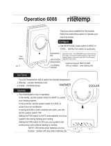
Touch the Power button once. The unit will automatically be in Cool
mode with the temperature set at 75°F (24°C) and the fan speed at
F1, the sleep setting.
To set mode of operation
When you
rst turn the unit on, it will be in the Cool mode (light on), with
constant fan.
2
Touch the Mode button once to activate the MoneySaver
®
(light on).
MoneySaver
®
ros serp mocehthtiwnafehtselcyctahterutaefasi
so that the fan does not run all the time. This saves energy and
eromrofnaftnats nocreferpyamuoyrO.noit ac i dim uh edsevorpmi
ehthcuot,naftnatsnocotnruterot(tnem evomria Mode button two
more times).
In order to run the fan by itself, do the following:
3
ContinuingfromMoneySaver
®
mode (light on), touchtheMode button
once to activate the FAN ONLY feature (light on).
The FAN ONLY setting will circulate air in the room without the com-
pressor coming on.
To adjust temperature
4
Use the Mode button to select either the COOL or MoneySaver
®
function
5
COOLER – Touch the button to lower the room air temperature.
6
WARMER – Touch the button to raise the room air temperature.
7
Press both the and ehthctiwsotemitemasehttasnottub
temperature readout from Fahrenheit (°F) to Celsius (°C).
Repeat step 7 to switch from °C back to °F.
To adjust fan speed
8
Touch the Fan Speed button to see the current setting. Touch it again
to change speed. F1 is the lowest setting (SLEEP SETTING / LOW),
F2 is MEDIUM, and F3 is HIGH.
To activate Smart Fan
9
There is a fourth option, SF, when selecting the fan speed. This is
the SMART FAN function. SMART FAN DOES NOT OPERATE IN
CONJUCTION WITH THE FAN ONLY MODE.
Smart Fan will adjust the fan speed automatically to maintain the
desired comfort level. For example, if the outside doors in your home
are opened for an extended period of time, or more people enter a
room, Smart Fan may adjust to a higher fan speed to compensate
for the increased heat load. This keeps you from having to adjust the
fan speed on your own.
How to operate the Friedrich room air conditioner (XQ models)
PM
Temp/Hour
Cool
MoneySaver
®
Fan Only
Clock
StartTime
Stop Time
Power
Fan
Speed
Mode
Timer
Set
Hour
10 11 12
13
7
3 4
5
6
18 9 2
Figure 5
To set the hour clock
10
Touch the Set Hour button to see the current setting (clock light
comes on). The number that is displayed is the approximate time
(hour only). Use the and buttons to change the settings. BE
SURE TO SET A.M. AND P.M. ACCORDINGLY. (P.M. is indicated
by a red light in the upper left corner of the display).
To set the timer
NOTE: Set the HOUR CLOCK before attempting to set timer functions.
You can set the START and STOP times a minimum of one hour apart, and
a maximum of twenty-three hours apart.
11
After setting the time, press the Set Hour button once (Start light
comes on). Use the and buttons to select the time that the
unit will START.
12
After selecting the START time, press the Set Hour button once more
(Stop light comes on). Use the
and buttons to select the time
that the unit will STOP. After selecting the stopping time, press the
Set Hour button once.
13
Press the Timer On/Off button (light turns on) to activate the timer
function. To deactivate this function, press the Timer On/Off button
once again (light turns off). Once the on and off times have been
selected, they will remain in memory and cycle daily until changed.
NOTE: If the unit is unplugged or the power is interrupted, the HOUR
must be reset or the Timer On/Off will not function when desired.
Automatic component protection
Your unit is equipped with Automatic Component Protection. To protect the
compressor of the unit, there is a three minute start delay if you turn the unit
off or if power is interrupted. The fan operation will not be affected. Also, if you
switch from Cool mode to Fan Only, and switch back to Cool mode, there
is a three minute delay before the compressor comes back on.
9
Figure 3
PM
X Star
Temp/Hour
Cool
Money Saver
®
Fan Only
Clock
Start Time
Stop Time
Power
Fan
Speed
Mode
Timer
On/Off
Set
Hour
10 11 12
13
7
3 4
5
6
18 9 2

To set the timer
NOTE: You can set the START and STOP times a minimum of one hour
apart, and a maximum of 23 hours apart.
9
TIMER START - Press Start .gniloocrofemittratstnerrucehtweivot
Continue pressing the Start button until you arrive at the start time
you desire. The start time for cooling will then be set.
10
TIMER STOP - Press the Stop button. Continue pressing the Stop
button until you arrive at the stop time you desire. The stop time for
cooling will then be set.
11
TIMER ON / OFF - Press the On/Off button to activate (light on) or
deactivate (light off) the timer. Once the on and off times have been
selected, they will remain in memory and cycle daily until changed.
NOTE: If the unit is unplugged or the power is interrupted, the Set Hr.
function must be reset or the On/Off function will not work.
How to use the remote control
To start unit
1
POWER - Press the Power button once. The unit will automatically
start in the mode and fan speed it was last left on.
To set mode of operation
2
COOL - Press the Cool button to automatically switch the operating
mode to COOL.
3
FAN ONLY - Press the Fan Only button if you want to run the fan
only.
4
MoneySaver
®
- Press the MoneySaver
®
button to activate the
MoneySaver
®
feature. This feature cycles the fan with the compres-
sor so that the fan does not run all the time.
To adjust temperature setting
5
WARMER - Press the Warmer button to raise the temperature
setting.
6
COOLER - Press the Cooler button to lower the temperature
setting.
To adjust fan speed
7
FAN SPEED - Press the Fan Speed button to see the current set-
ting. Press again to change the fan speed. F1 is the lowest setting
(SLEEP / LOW), F2 is MEDIUM, F3 is HIGH, and SF is the SMART
FAN setting.
To set the hour clock
8
SET HOUR CLOCK - Press Set Hr. once to see the current clock
setting. Continue pressing the button until you arrive at the current
time (Hour only). Minutes are not shown on the display. Make sure
that the A.M. / P.M. setting is correct.
Additional RC1 wireless remote controls can be purchased from your Friedrich dealer.
(XQ models)
Money
Fan
Set Hr.
Stop
Start
Temperature
Fan
Cool
On/O
Cooler
Warmer
Only Speed Saver
®
Power
Timer Operation
8
10
7
11
9
43
12
56
10
How To Operate The EQ08
Function Control Knob
The left knob is a six position control that allows you to
select heat or cool in either low speed or high speed. Plus
you can select fan only if you wish.
Thermostat Knob
The right hand knob is the thermostat - turn it clockwise for
cooler, counter-clockwise for warmer.

MODE CONTROL
The mode control pad(s) allow the selection of the operating
modes of the unit.
There is a two second delay before the mode activates its
appropriate relay.
OPERATING SEQUENCE / CHARACTERISTICS
AND FEATURES
Compressor Operation
The run state of the compressor is determined by the
difference between the indoor ambient temperature and
the set temperature. See specifi c mode of operation for
details.
Compressor Time Delay: 180 seconds
This feature is initiated every time the compressor is de-
energized, either due to:
(1) satisfying the temperature set point
(2) changing mode to fan only
(3) a power interruption or
(4) turning the unit off
The compressor is also time delayed for 3 minutes when the
control is fi rst plugged in or power is restored after failure.
When the compressor cycles off as a result of satisfying the
“load”, the time delay is typically timed out during the off
cycle. Compressor time delay is bypassed by “Test Mode”.
Return Air Temperature Sensor
The control range is 60°F to 90°F +/- 2.0°F.
Frost Protection Sensor
Temperature settings:
Disable the compressor when sensing 30° +/- 3°F for 2
minutes continuously.
Enable compressor @ 55° +/- 5°F.
The fan should not be affected by the Frost Protection. It
should continue to function normally if freeze protection is
called for.
COOL MODE FOR XQ MODELS
When in the COOL mode, the control will turn on the
compressor when the indoor temperature is 1.5°F above the
set point and turn off the compressor when the ambient gets
below the set point by 1.5°F. The fan will run continuously.
MONEY SAVER MODE
When in MONEY SAVER mode, the system will be turned
on when the indoor temperature gets above the set point by
0.75°F and turns off when the indoor temperature gets below
the set point by 0.75°F. The fan will turn on 5 seconds before
the compressor and turn off 5 seconds after the compressor
stops. If the compressor is delayed the fan will continue to
run while the compressor restarts. If the thermostat remains
satisfi ed for more than approximately 9 minutes, the fan will
turn on for a period of 90 seconds for air sampling. Operation
in MONEY SAVER mode will light both the MONEY SAVER
and COOL indicators.
ELECTRONIC CONTROL SEQUENCE OF OPERATION
11
FAN ONLY MODE
When in the FAN ONLY mode, the compressor will not
operate. The fan will run continuously at the user-selected
speed (see “Fan Speed Set” below). Smart Fan is not
available in FAN ONLY Mode.
FAN SPEED SET
XQ fan speed is changed by pressing FAN SPEED button
and scrolling through F1, F2, F3 and SF (Smart Fan) in the
digital display.
There will be a 2 second delay before the fan speed changes
to prevent unnecessary switching of the relays during fan
speed selection.
SMART FAN
On the XQ model, smart fan is activated by pressing the
FAN SPEED button and scrolling through speeds until
“SF” appears in the digital display. Using the remote
control, Smart Fan is selected by the fourth push of Fan
Speed button.
Smart fan changes fan speeds based on the temperature
differential between the ambient and set temperatures.
CHECKING ROOM TEMPERATURE
Check the room temperature at the electronic control
pad by pressing the “FAN SPEED” button and the
“TEMP ” button at the same time on XQ models.
The indoor temperature will display for 10 seconds. Indoor
temperature can be viewed in all modes, including the
TEST mode. The display can be changed back to SET
temperature by pressing any key, except the ON/OFF
button, or after 10 seconds has elapsed.
KEEP ALIVE
The electronic control has a memory to retain all functions
and status as set up by the user in the event of a power
failure. Once power is restored to the unit there is a two
second delay before the fan comes on and approximately
three minutes delay before the compressor is activated,
providing that the mode was set for cooling and the set
point temperature has not been met in the room.
REBOOT/RESET THE CONTROL BOARD
With unit on, press “MODE” and “TEMP/HOUR ” buttons
simultaneously for 10 seconds. If the panel will reboot, you
will hear the fan come on and the temperature window
will read 60°F. If this happens, turn the unit off for about
10 seconds and then turn it back on to fi nish the reboot
cycle. If the panel does not reboot, you possibly need to
replace it.

MECHANICAL COMPONENTS
Plenum assembly Diffuser with directional louvers used
to direct the conditioned airfl ow.
Blower wheel Attaches to the indoor side of the fan motor
shaft and is used for distributing unconditioned, room side
air though the heat exchanger and delivering conditioned
air into the room.
Slinger fan blade Attaches to the outdoor side of the fan
motor shaft and is used to move outside air through the
condenser coil, while slinging condensate water out of the
base pan and onto the condenser coil, thus lowering the
temperature and pressu
res within the coil.
ELECTRICAL COMPONENTS
Thermostat Used to maintain the specifi ed room side
comfort level
System switch Used to regulate the operation of the fan
motor, the compressor or to turn the unit off. For troubleshoot-
ing, refer to the wiring diagrams and schematics in the back
of this service manual.
Capacitor Reduces line current and steadies the voltage
supply, while greatly improving the torque characteristics of
the fan motor and compressor motor.
MoneySaver
®
switch When engaged, it sends the power
supply to the fan motor through the thermostat, which allows
Smart Fan
Automatically adjusts the fan speed to main-
tain the desired room temp.
for a cycle-fan operation.
Fan Motor Dual-shafted fan motor operates the indoor
blower wheel and the condenser fan blade simultaneously.
Heating element Electric resistance heater, available in
EQ08 model.
Heat anticipator Used to provide better thermostat and
room air temperature control.
HERMETIC COMPONENTS
Compressor Motorized device used to compress refrigerant
through the sealed system.
Capillary tube A cylindrical meter device used to evenly dis-
tribute the fl ow of refrigerant to the heat exchangers (coils.)
FUNCTIONAL COMPONENT DEFINITIONS
12

13
TESTING THE ELECTRONIC CONTROL
BOARDS FOR XQ MODELS
Activating Test Mode:
Activate test mode by pressing at the same time the
“MODE” button and the “TEMP ” button on XQ
models. LEDs for Hour, Start, and Stop will blink 1 bps
while Test Mode is active.
Test Mode has duration of 90 minutes. Test Mode can
be activated under any conditions, including Off. Test
Mode is cancelled by pressing the On/Off button,
unplugging the unit, or when the 90 minutes is timed
out. All settings revert to the factory default settings of
Cool, 75 degrees F, Timer and Set Hour features are
nonfunctional.
Test Mode overrides the three-minute lockout, all
delays for compressor and fan motor start / speed
change, and no delay when switching modes.
During Test Mode, the default settings are; Unit ON,
Money Saver ON, 60°F, and High fan speed.
IMPORTANT: Error Codes are cleared from the
log by exiting from Error Code Mode. To exit on XQ
models, press Timer On/Off button. Or unplug unit to
exit Error Code Mode. Plug unit in after 5 seconds to
resume normal operation of unit.
Activating Error Code Mode: (Submode of Test Mode)
Unit must be in Test Mode to enter Error Code Mode
1. Activate Error Code Mode by pressing the “TIMER ON/
OFF” button on XQ models. LED for the “TIMER ON/OFF”
will fl ash 1 bps while Error Code Mode is active. Pressing
the “TEMP/HR ” button will display 00. Consecutive
presses will scroll through all error codes logged. Press
the “TEMP/HR ” button to see the reverse order of all
error codes logged. When the end of logged error codes is
reached the temperature set point will appear.
COMPONENTS TESTING
ERROR CODE LISTINGS
E1 SHORT CYCLE SITUATION: Defi ned as (compressor
powered on before the three minute time delay ten times in
one hour. Investigate and correct short cycling problem.
E2 KEYBOARD STUCK ERROR: If key button(s) are
pressed continuously for twenty seconds or more. If MODE
key is stuck, unit will default to cool. Exit Error Code
Mode to see if error “E2” is no longer displayed and unit is
functioning. Replace board if “E2” still displays after exiting
Error Code Mode.
E3 FROST PROBE OPEN: Normal operation is allowed.
Ohm frost probe. Replace probe if ohm value not read. If
ohm value is present replace board.
E4 FROST PROBE SHORT: Normal operation allowed.
Replace probe.
E5 INDOOR PROBE OPEN: Control assumes indoor
ambient temperature is 90 degree F and unit will operate.
Ohm indoor probe. Replace probe if ohm value not read.
E6 INDOOR PROBE SHORT: Control assumes ambient
temperature is 90 degree F and unit will operate. Replace
probe.
NOTE: All Error Code displays for Frost & Indoor Probe
will allow unit to operate. Unit may or will ice up if faulty
components not replaced.
FROST PROBE SENSOR: disables compressor at 35
degrees F.
INDOOR PROBE SENSOR: Control range is 60°F to 90°F
+/- 2°F.
Indoor temperature will be displayed by pressing:
(XQ units) The Fan Speed button and the “TEMP ”
button.
The indoor temperature will be displayed for 10 seconds.
The display will change back to the Set Point temperature
by pressing any key button except for the On/Off button.
The indoor temperature can be viewed in all modes,
including test mode.
PM
X Star
Temp/Hour
Cool
Money Saver
®
Fan Only
Clock
Start Time
Stop Time
Power
Fan
Speed
Mode
Timer
On/Off
Set
Hour

TEST:
1. Remove leads from thermostat.
2. Turn thermostat knob clockwise to its coldest
position.
3. Test for continuity between the two terminals. Contacts
should be closed.
4. Turn thermostat knob counterclockwise to its warmest
position.
5. Test for continuity - contacts should be open.
NOTE: The thermostat must be within the temperature
range listed to open and close.
To maintain the comfort level desired, a cross ambient type
thermostat is used. The thermostat has a range from 60°
±2°F to 92° ±3°F. The thermos
tat bulb is positioned in front
of the evaporator coil to sense the return air temperature.
Thermostat malfunction or erratic operation is covered in
the troubleshooting section of this manual.
THERMOSTAT (“EQ08” Models)
(See Figure 17)
This thermostat is single pole-double throw, cross ambient
with a range of 60° to 92°F and a differential of ±2°F. Terminal
“2” is common.
Figure 17
Thermostat
(EQ Model)
Figure 18
Thermostat
TEST:
Cooling/Heating Models: Remove wires from thermostat
and check continuity between terminal “2” (common) and
“3” for cooling. Check between terminals “2” (common)
and “1” for heating. Also check that contacts in thermostat
open after placing in either position. NOTE: Temperature
must be within range listed to check thermostat. Refer to
the troubleshooting section in this manual for additional
information on thermostat testing.
THERMOSTAT ADJUSTMENT
No attempt should be made to adjust thermostat. Due
to the sensitivity of the internal mechanism and the
sophisticated equipment required to check the calibration,
it is suggested that the thermostat be replaced rather than
calibrated. Thermostat bulb must be straight to insure
proper performance.
THERMOSTAT BULB LOCATION
The position of the bulb is important in order for the
thermostat to function properly. The bulb of the thermostat
should be located approximately 45° to a maximum of 60°
from horizontal. Also, do not allow the thermostat bulb to
touch the evaporator coil. (See Figures 17 and 18)
Thermostat sensor holder 020
to be positioned between the
4th and 5th and 6th and 7th
rows of tubes from the bottom
of the coil at dimension shown
Figure 19
Thermostat Bulb Location
(EQ Model)
COMPONENTS TESTING (Continued)
ELECTRIC SHOCK HAZARD
WARNING
Disconnect power to the unit before
servicing. Failure to follow this warning
could result in serious injury or death.
EQ08 SYSTEM CONTROL SWITCH - TEST
“EQ08” SYSTEM CONTROL SWITCH – TEST
Turn knob to phase of switch to be tested. There must be
continuity as follows:
1. “Fan Only” Position – between terminals “MS” and “H”
2. “Hi Cool” Position – between terminals “L1” and “C” and
“MS” and “H”
3. “Low Cool” Position – between terminals “L1” and “C”
and “MS” and “LO”
4. “Low Heat” Position – between terminals “L2” and “2”
and “MS” and “LO”
5. “Hi Heat” Position – between terminals “L2” and “2” and
“MS” and “H”
L1
MS
2
H
LO
C
L2
B1
System Control Switch
(EQ Models)
14

CAPACITORS
ELECTRIC SHOCK HAZARD
WARNING
Turn off electric power before servicing.
Discharge capacitor with a 20,000 Ohm 2 Watt
resistor before handling.
Failure to do so may result in personal injury,
or death.
Many motor capacitors are internally fused. Shorting the
terminals will blow the fuse, ruining the capacitor. A 20,000
ohm 2 watt resistor can be used to discharge capacitors
safely. Remove wires from capacitor and place resistor
across terminals. When checking a dual capacitor with
a capacitor analyzer or ohmmeter, both sides must be
tested.
Capacitor Check with Capacitor Analyzer
The capacitor analyzer will show whether the capacitor is
“open” or “shorted.” It will tell whether the capacitor is within
its micro farads rating and it will show whether the capacitor
is operating at the proper power-factor percentage. The
instrument will automatically discharge the capacitor when
the test switch is released.
Capacitor Connections
The starting winding of a motor can be damaged by a
shorted and grounded running capacitor. This damage
usually can be avoided by proper connection of the running
capacitor terminals.
From the supply line on a typical 230 volt circuit, a 115 volt
potential exists from the “R” terminal to ground through a
possible short in the capacitor. However, from the “S” or
start terminal, a much higher potential, possibly as high as
400 volts, exists because of the counter EMF generated
in the start winding. Therefore, the possibility of capacitor
failure is much greater when the identifi ed terminal is
connected to the “S” or start terminal. The identifi ed
terminal should always be connected to the supply line, or
“R” terminal, never to the “S” terminal.
When connected properly, a shorted or grounded running
capacitor will result in a direct short to ground from the “R”
terminal and will blow the line fuse. The motor protector
will protect the main winding from excessive temperature.
Dual Rated Run Capacitor Hook-up
FIGURE 24
BLOWER/FAN MOTOR - TEST
1. Determine that capacitor is serviceable.
2. Disconnect fan motor wires from fan speed switch or
system switch.
3. Apply “live” test cord probes on black wire and common
terminal of capacitor. Motor should run at high speed.
4. Apply “live” test cord probes on red wire and common
terminal of capacitor. Motor should run at low speed.
5. Apply “live” test cord probes on each of the remaining
wires from the speed switch or system switch to test
intermediate speeds. If the control is in the “MoneySaver”
mode and the thermostat calls for cooling, the fan will
start - then stop after approximately 2 minutes; then the
fan and compressor will start together approximately 2
minutes later.
Figure 23
Blower/Fan Motor
FAN MOTOR
A single phase permanent split capacitor motor is used to drive
the evaporator blower and condenser fan. A self-resetting
overload is located inside the motor to protect against high
temperature and high amperage conditions. (See Figure 23)
ELECTRIC SHOCK HAZARD
WARNING
Disconnect power to the unit before
servicing. Failure to follow this warning
could result in serious injury or death.
COMPONENTS TESTING (Continued)
15

HEATING ELEMENT (See Figure)
All electric heat models are equipped with a heating element.
The EQ08 has a 1.15 KW element.
The heating element contains a fuse link and a heater limit
switch. The fuse link is in series with the power supply and
will open and interrupt the power when the temperature
reaches 199°F or a short circuit occurs in the heating
element. Once the fuse link separates, a new fuse link
must be installed.
NOTE: Always replace with the exact replacement.
The heater element has a high limit control. This control
is a bimetal thermostat mounted in the top of the heating
element.
Should the fan motor fail or fi lter become clogged, the high
limit control will open and interrupt power to the heater
before reaching an unsafe temperature condition.
The control is designed to open at 110°F ±6°F. Test
continuity below 110°F and for open above 110°F.
TESTING THE HEATING ELEMENT
Testing of the elements can be made with an ohmmeter
across the terminals after the connecting wires have been
removed. A cold resistance reading of approximately 10.11
ohms for the 1.15 KW heater should be registered.
Figure
Heating Element
DRAIN PAN VALVE
During the cooling mode of operation, condensate which
collects in the drain pan is picked up by the condenser fan
blade and sprayed onto the condenser coil. This assists
in cooling the refrigerant plus evaporating the water.
During the heating mode of operation, it is necessary that
water be removed to prevent it from freezing during cold
outside temperatures. This could cause the condenser
fan blade to freeze in the accumulated water and prevent
it from turning.
To provide a means of draining this water, a bellows type
drain valve is installed over a drain opening in the base
pan.
This valve is temperature sensitive and will open when
the outside temperature reaches 40°F. The valve will
close gradually as the temperature rises above 40°F to
fully close at 60°F.
Figure 26
Bellows Assembly
Drain Pan Valve
COMPONENTS TESTING (Continued)
ELECTRIC SHOCK HAZARD
WARNING
Disconnect power to the unit before
servicing. Failure to follow this warning
could result in serious injury or death.
16

Suction
Line
Evaporator
Coil
Metering
Device
Refrigerant
Strainer
Discharge
Line
Condenser
Coil
Compressor
Refrigerant Drier
Liquid
Line
A good understanding of the basic operation of the
refrigeration system is essential for the service technician.
Without this understanding, accurate troubleshooting of
refrigeration system problems will be more diffi cult and time
consuming, if not (in some cases) entirely impossible. The
refrigeration system uses four basic principles (laws) in its
operation they are as follows:
1. “Heat always fl ows from a warmer body to a cooler
body.”
2. “Heat must be added to or removed from a substance
before a change in state can occur”
3. “Flow is always from a higher pressure area to a lower
pressure area.”
4. “The temperature at which a liquid or gas changes state
is dependent upon the pressure.”
The refrigeration cycle begins at the compressor. Starting
the compressor creates a low pressure in the suction line
which draws refrigerant gas (vapor) into the compressor.
The compressor then “compresses” this refrigerant, raising
its pressure and its (heat intensity) temperature.
The refrigerant leaves the compressor through the discharge
Line as a hot High pressure gas (vapor). The refrigerant
enters the condenser coil where it gives up some of its
heat. The condenser fan moving air across the coil’s fi nned
surface facilitates the transfer of heat from the refrigerant to
the relatively cooler outdoor air.
When a suffi cient quantity of heat has been removed from
the refrigerant gas (vapor), the refrigerant will “condense”
(i.e. change to a liquid). Once the refrigerant has been
condensed (changed) to a liquid it is cooled even further by
the air that continues to fl ow across the condenser coil.
The RAC design determines at exactly what point (in the
condenser) the change of state (i.e. gas to a liquid) takes
place. In all cases, however, the refrigerant must be
totally condensed (changed) to a Liquid before leaving the
condenser coil.
The refrigerant leaves the condenser Coil through the liquid
line as a warm high pressure liquid. It next will pass through
the refrigerant drier (if so equipped). It is the function of the
drier to trap any moisture present in the system, contaminants,
and large particulate matter.
The liquid refrigerant next enters the metering device. The
metering device is a capillary tube. The purpose of the
metering device is to “meter” (i.e. control or measure) the
quantity of refrigerant entering the evaporator coil.
In the case of the capillary tube this is accomplished (by
design) through size (and length) of device, and the pressure
difference present across the device.
Since the evaporator coil is under a lower pressure (due to
the suction created by the compressor) than the liquid line,
the liquid refrigerant leaves the metering device entering the
evaporator coil. As it enters the evaporator coil, the larger
area and lower pressure allows the refrigerant to expand
and lower its temperature (heat intensity). This expansion is
often referred to as “boiling”. Since the unit’s blower is moving
indoor air across the fi nned surface of the evaporator coil,
the expanding refrigerant absorbs some of that heat. This
results in a lowering of the indoor air temperature, hence the
“cooling” effect.
The expansion and absorbing of heat cause the liquid
refrigerant to evaporate (i.e. change to a gas). Once the
refrigerant has been evaporated (changed to a gas), it is
heated even further by the air that continues to fl ow across
the evaporator coil.
The particular system design determines at exactly what
point (in the evaporator) the change of state (i.e. liquid to a
gas) takes place. In all cases, however, the refrigerant must
be totally evaporated (changed) to a gas before leaving the
evaporator coil.
The low pressure (suction) created by the compressor
causes the refrigerant to leave the evaporator through the
suction line as a cool low pressure vapor. The refrigerant then
returns to the compressor, where the cycle is repeated.
REFRIGERATION SEQUENCE OF OPERATION
17

• R-410A pressure is approximately 60% higher than R-22 pressure.
• R-410A cylinders must not be allowed to exceed 125 F, they may leak or rupture.
• R-410A must never be pressurized with a mixture of air, it may become
fl ammable.
• Servicing equipment and components must be specifi cally designed for use with R-410A and
dedicated to prevent contamination.
• Manifold sets must be equipped with gauges capable of reading 750 psig (high side) and 200
psig (low side), with a 500-psig low-side retard.
• Gauge hoses must have a minimum 750-psig service pressure rating
• Recovery cylinders must have a minimum service pressure rating of 400 psig, (DOT 4BA400
and DOT BW400 approved cylinders).
• POE (Polyol-Ester) lubricants must be used with R-410A equipment.
• To prevent moisture absorption and lubricant contamination, do not leave the refrigeration
system open to the atmosphere longer than 1 hour.
• Weigh-in the refrigerant charge into the high side of the system.
• Introduce liquid refrigerant charge into the high side of the system.
• For low side pressure charging of R-410A, use a charging adaptor.
• Use Friedrich approved R-410A fi lter dryers only.
The following is a list of important considerations when working with R-410A equipment
R-410A SEALED SYSTEM REPAIR CONSIDERATIONS
Do not puncture, heat, expose to fl ame or incinerate.
Only certifi ed refrigeration technicians should
service this equipment.
R410A systems operate at higher pressures than
R22 equipment. Appropriate safe service and
handling practicces must be used.
Only use gauge sets designed for use with R410A.
Do not use standard R22 gauge sets.
WARNING
Refrigeration system under high pressure
18

Proper refrigerant charge is essential to proper unit operation.
Operating a unit with an improper refrigerant charge will
result in reduced performance (capacity) and/or effi ciency.
Accordingly, the use of proper charging methods during
servicing will insure that the unit is functioning as designed
and that its compressor will not be damaged.
Too much refrigerant (overcharge) in the system is just as bad
(if not worse) than not enough refrigerant (undercharge). They
both can be the source of certain compressor failures if they
remain uncorrected for any period of time. Quite often, other
problems (such as low air fl ow across evaporator, etc.) are
misdiagnosed as refrigerant charge problems. The refrigerant
circuit diagnosis chart will assist you in properly diagnosing
these systems.
An overcharged unit will at times return liquid refrigerant
(slugging) back to the suction side of the compressor eventually
causing a mechanical failure within the compressor. This
mechanical failure can manifest itself as valve failure, bearing
failure, and/or other mechanical failure. The specifi c type of
failure will be infl uenced by the amount of liquid being returned,
and the length of time the slugging continues.
Not enough refrigerant (undercharge) on the other hand, will
cause the temperature of the suction gas to increase to the point
where it does not provide suffi cient cooling for the compressor
motor. When this occurs, the motor winding temperature will
increase causing the motor to overheat and possibly cycle open
the compressor overload protector. Continued overheating of
the motor windings and/or cycling of the overload will eventually
lead to compressor motor or overload failure.
Sealed Refrigeration System contains refrigerant
and oil under high pressure.
Proper safety procedures must be followed,
and proper protective clothing must be worn
when working with refrigerants.
Failure to follow these procedures could
result in serious injury or death.
WARNING
HIGH PRESSURE HAZARD
Unplug and/or disconnect all electrical power
to the unit before performing inspections,
maintenances or service.
Failure to do so could result in electric shock,
serious injury or death.
WARNING
RISK OF ELECTRIC SHOCK
R-410A SEALED REFRIGERATION SYSTEM REPAIRS
SEALED SYSTEM REPAIRS TO COOL-ONLY MODELS REQUIRE THE INSTALLATION OF A LIQUID LINE DRIER.
IMPORTANT
EQUIPMENT REQUIRED:
1. Voltmeter
2. Ammeter
3. Ohmmeter
4. E.P.A. Approved Refrigerant Recovery System
5. Vacuum Pump (capable of 200 microns or less
vacuum.)
6. Acetylene Welder
7. Electronic Halogen Leak Detector capable of
detecting HFC (Hydrofl uorocarbon) refrigerants.
8. Accurate refrigerant charge measuring device such
as:
a. Balance Scales - 1/2 oz. accuracy
b. Charging Board - 1/2 oz. accuracy
9. High Pressure Gauge - (0 to 750 lbs.)
10. Low Pressure Gauge - (-30 to 200 lbs.)
11. Vacuum Gauge - (0 - 1000 microns)
12. Facilities for fl owing nitrogen through refrigeration tubing
during all brazing processes.
EQUIPMENT MUST BE CAPABLE OF:
1. Recovering refrigerant to EPA required levels.
2. Evacuation from both the high side and low side of the
system simultaneously.
3. Introducing refrigerant charge into high side of the
system.
4. Accurately weighing the refrigerant charge introduced
into the system.
Refrigerant Charging
NOTE: Because the XStar system is a sealed system,
service process tubes will have to be installed. First install a
line tap and remove refrigerant from system. Make necessary
sealed system repairs and vacuum system. Crimp process
tube line and solder end shut. Do not leave a service valve in
the sealed system.
19
/