Lowrance GlobalMap 100 User manual
- Category
- Navigators
- Type
- User manual

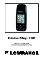
INSTALLATION AND
OPERATION INSTRUCTIONS
GlobalMap 100
®

Copyright © 1996, 1997, 1998, 2000 Lowrance Electronics, Inc.
All rights reserved.
GlobalMap
®
100 and Lowrance
®
are registered trademarks of Lowrance
Electronics, Inc.
WARNING!
USE THIS UNIT ONLY AS AN AID TO NAVIGATION. A CAREFUL NAVI-
GATOR NEVER RELIES ON ONLY ONE METHOD TO OBTAIN POSI-
TION INFORMATION.
Never use this product while operating a vehicle.
CAUTION
When showing navigation data to a position (waypoint), this unit will show
the shortest, most direct path to the waypoint. It provides navigation data
to the waypoint regardless of obstructions. Therefore, the prudent naviga-
tor will not only take advantage of all available navigation tools when trav-
elling to a waypoint, but will also visually check to make certain a clear,
safe path to the waypoint is always available.
The operating and storage temperature for your unit is from -4 degrees to
+167 degrees Fahrenheit (-20 to +75 degrees Celsius). Extended storage
temperatures higher or lower than specified will cause the liquid crystal
display to fail. Neither this type of failure nor its consequences are cov-
ered by the warranty. For more information, consult the factory customer
service department.
All features and specifications subject to change without notice.
Lowrance Electronics may find it necessary to change or end our poli-
cies, regulations, and special offers at any time. We reserve the right to do
so without notice.
All screens in this manual are simulated.

This device complies with Part 15 of the FCC Rules. Operation is subject
to the following two conditions: (1) this device may not cause harmful
interference, and (2) this device must accept any interference received,
including interference that may cause undesired operation.
Note:
This equipment has been tested and found to comply with the limits for a
Class B digital device, pursuant to Part 15 of the FCC Rules. These limits
are designed to provide reasonable protection against harmful interfer-
ence in a residential installation. This equipment generates, uses and can
radiate radio frequency energy and, if not installed and used in accor-
dance with the instructions, may cause harmful interference to radio com-
munications. However, there is no guarantee that interference will not oc-
cur in a particular installation. If this equipment does cause harmful inter-
ference to radio or television reception, which can be determined by turn-
ing the equipment off and on, the user is encouraged to try to correct the
interference by one or more of the following measures:
• Reorient or relocate the receiving antenna.
• Increase the separation between the equipment and receiver.
• Connect the equipment into an outlet on a circuit different from that to
which the receiver is connected.
• Consult the factory customer service department for help.
Specifications
Dimensions.................................................6.75” L x 2.25” W x 1.625” D
Display.................................................................. 160 H x 104 W pixels
Power ....................................................................................... 5-35 vdc
Waypoints.........................................................................................750
Routes ................................................................................................99
Waypoints per Route (maximum)........................................................99
Total Waypoints used in Routes......................................................1500
Icons...............................................................................................1000
Savable Plot Trails.................................................................................3
Maximum Plot Trail Points.................................................. 3000 per trail

INTRODUCTION ............................................................................................................1
DGPS - What is it?...................................................................................................2
Don’t Get Lost ..........................................................................................................2
GETTING STARTED ......................................................................................................2
Power .................................................................................................................2
BATTERIES..............................................................................................................2
Battery Installation.............................................................................................3
OPERATION .................................................................................................................3
Keyboard .................................................................................................................3
Menus .................................................................................................................4
Turning Power On ....................................................................................................4
Satellite Status Screen ............................................................................................4
Finding Your Position................................................................................................5
Auto Search .......................................................................................................5
Manual Initialization...........................................................................................6
Position Acquisition ...........................................................................................6
POSITION/NAVIGATION SCREENS ......................................................................7
Navigation Screens ...........................................................................................7
Course Deviation Indicator (CDI)................................................................9
Map .................................................................................................................10
Cursor .........................................................................................................11
Map Setup...................................................................................................11
Change Maps..............................................................................................11
Map Options ......................................................................................................11
Map Orientation ..........................................................................................11
Autozoom ....................................................................................................13
Range Rings/Grid Lines..............................................................................14
Earth Map Options ............................................................................................14
Earth Map On/Off .......................................................................................14
Text Labels ..................................................................................................15
Locations.....................................................................................................15
Map Detail ...................................................................................................15
Gray Fill .......................................................................................................16
Plot Trail Options ...............................................................................................16
Clear Trail ....................................................................................................16
Flash Trail ....................................................................................................16
Update Options ...........................................................................................17
Save Trail .................................................................................................17
Show Trail.................................................................................................17
ICONS ...............................................................................................................17
Place Icon - Present Position ..................................................................18
Place Icon - Cursor Position....................................................................18
Icon Options ............................................................................................19
MAP DOWNLOADING ......................................................................................20
WINDOWS.........................................................................................................22
Reprogram Window Groups .......................................................................27
Reprogram Boxes .......................................................................................28
RESET GROUPS ..............................................................................................29
WAYPOINTS......................................................................................................29
Waypoint Menu ...........................................................................................29
Saving Your Present Position as a Waypoint (Quick Save Method)...........29
Saving The Cursor Position as a Waypoint ................................................30
Saving Your Present Position as a Waypoint (Select Number Method) .....30
Saving a New Position ................................................................................31
Waypoint Averaging ....................................................................................31

Project a Waypoint ......................................................................................32
Selecting a Waypoint ..................................................................................33
Waypoint Number .......................................................................................33
Waypoint List...............................................................................................33
Editing a Waypoint ......................................................................................33
Edit Position .............................................................................................33
Edit Name ................................................................................................34
Edit Icon...................................................................................................34
WAYPOINT NAVIGATION........................................................................................34
Navigating to a cursor location..........................................................................34
Navigating to a Waypoint using the Map...........................................................35
OTHER WAYPOINT OPTIONS .........................................................................35
Move a Waypoint.........................................................................................35
Delete a Waypoint .......................................................................................36
Delete All Waypoints ...................................................................................36
ROUTES .................................................................................................................37
Create a Route ..................................................................................................37
Add From Waypoint List..............................................................................37
Add From Map ............................................................................................38
Delete a Waypoint .............................................................................................38
Waypoint Statistics ............................................................................................39
Following a Route ..............................................................................................39
Waypoint Information ..................................................................................40
Delete a Route...................................................................................................41
CANCEL NAVIGATION............................................................................................41
Navigation Notes......................................................................................................41
SYSTEM SETUP .....................................................................................................42
Sound ................................................................................................................42
Contrast .............................................................................................................42
Set Local Time...................................................................................................42
Units of Measure ...............................................................................................43
NMEA / DGPS ...................................................................................................43
NMEA Output ....................................................................................................44
Configure NMEA Output ...................................................................................44
DGPS.................................................................................................................44
Serial Communication Setup.............................................................................46
Reset Options....................................................................................................46
Reset Groups ....................................................................................................47
System Info........................................................................................................47
GPS SETUP ............................................................................................................47
Power Save........................................................................................................47
Position Format .................................................................................................48
DATUM...............................................................................................................48
PCF (Position Correction Factor) ......................................................................49
POSITION PINNING .........................................................................................50
Map Fix ..............................................................................................................51
ALARMS .................................................................................................................52
MESSAGES .............................................................................................................52
SUNRISE/SET MOONRISE/SET CALCULATOR ...................................................53
SIMULATOR.............................................................................................................54
DEFINITION OF TERMS/ABBREVIATIONS ...........................................................55
DATUM LIST ............................................................................................................56

Notes:

1
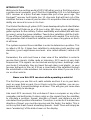
INTRODUCTION
Welcome to the exciting world of GPS! Whether you’re a first-time user or
a professional navigator, you’ll find the GlobalMap 100 is a full-featured
GPS receiver at a price that was impossible just a few years ago. The
Rockwell
®
receiver built inside has 12 channels that will track all of the
satellites that are in view of your location. It’s acquisition time and tracking
ability are second to none in its class.
The Global Positioning System (GPS) was developed by the United States
Department of Defense as a 24-hour a day, 365 days a year global navi-
gation system for the military. Civilian availability was added (but with less
accuracy) using the same satellites. Twenty-four satellites orbit the Earth.
Three of these satellites are spares, unused until needed. The rest virtu-
ally guarantee that at least four satellites are in view of anyplace on Earth
at all times.
The system requires three satellites in order to determine a position. This
is called a 2D fix. It takes four satellites to determine both position and
elevation, (your height above sea level - also called altitude.) called a 3D
fix.
Remember, the unit must have a clear view of the satellites in order to
receive their signals. Unlike radio or television, GPS works at very high
frequencies. The signals can be blocked easily by trees, buildings, even
your body. Fortunately, they do travel through glass and plastic, so your
receiver will work in the car, if it has a clear view of the satellites through
the windshield or side windows. Let someone else drive if you use it in a
car or other vehicle.
Never use this GPS receiver while operating a vehicle!
The first time you use this unit, walk outside and turn it on in your back-
yard, an open field or park. Once it locks onto the satellites, you can ex-
periment with it around buildings and trees. This will give you some idea
of its sensitivity to blockage.
Like most GPS receivers, this unit doesn’t have a compass or any other
navigation aid built inside. It relies solely on the signals from the satellites
to calculate a position. Speed, direction of travel, and distance are all
calculated from position information. Therefore, in order for it to determine
direction of travel, you must be moving and the faster, the better. This is
not to say that it won’t work at walking speeds - it will. There will simply be
more “wandering” of the data shown on the display.

2
DGPS - What is it?
If you want better performance, (and who doesn’t?) many manufacturers
(including Lowrance) sell a DGPS receiver that attaches to your GPS
receiver. The DGPS system transmits correction signals that increase the
accuracy of your unit. The DGPS receiver takes signals from these land-
based transmitters and gives them to the GPS receiver which then uses
them to show a more accurate position. (You can use the signals from all
of the Coast Guard DGPS stations for free, by the way.) The downside to
this is it requires another piece of electronic gear (the DGPS receiver)
which usually isn’t small enough to carry with you, but will work nicely on
a vehicle. And you have to be close enough to a station to receive the
DGPS signals.
Don’t Get Lost
Generally, you find that using your GPS receiver without DGPS is both
easy and amazingly accurate. It’s easily the most accurate method of
electronic navigation available to the general public today. Remember,
however, that this receiver is only a tool. Always have another method of
navigation available, such as a chart or map and a compass. It’s a good
idea to carry spare batteries with you, especially if you’re venturing into
unknown territory.
Also remember that this unit will always show navigation information in
the shortest line from your present position to a waypoint, regardless of
terrain! It only calculates position, it can’t know what’s between you and
your camp, for example. It’s up to you to safely navigate around obstacles,
no matter how you’re using this product.
GETTING STARTED
Power
The GlobalMap 100 operates from AA batteries or from 5 to 35 volts DC
using an optional external power cable. If the power cable is used, the
GlobalMap 100 automatically switches to it if the external power is greater
than the battery voltage. If the external power fails, the unit automatically
switches to the batteries.
BATTERIES
The unit requires four AA batteries. We recommend you use alkaline bat-
teries for the best trade-off between battery life and cost. However, you
can use nickel-cadmium (ni-cad), or lithium batteries. You can also use
rechargeable alkaline batteries such as RayOVac
®
Renewals
®
. With the
exception of lithium, none of the above batteries will last as long as stan-
dard alkaline batteries. We recommend DURACELL
®
brand, but others
will work. Do not use “heavy-duty” batteries or any type other than the

3
ones listed above. Do not mix different
types of batteries. (For example, don’t
use both alkaline and ni-cad batteries at
the same time.)
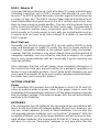
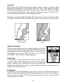
Battery Installation
First turn the unit so that its back is fac-
ing you. Push the two tabs to the left and
remove the battery cover as shown at
right. Install the batteries according to this
diagram. (There’s a decal in the battery
compartment showing the correct polar-
ity, also.) Replace the battery compartment
cover and the unit is ready for use.
External Antenna
Although this GPS receiver is extremely sensitive, it can be used in loca-
tions where the built-in antenna simply cannot receive signals from enough
satellites. A second connector on the back of the unit is for an external
antenna. The Lowrance model EA-3 antenna plugs directly into this con-
nector. Other antennas may work. If you use an antenna other than
Lowrance, it will need to be a passive antenna. This unit does not supply
power to the antenna.
Note: There are two plastic caps that cover the power and external an-
tenna connectors. Simply pry these caps off to gain access to the con-
nectors.
OPERATION
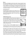
Keyboard
There are 12 keys on the keyboard. You navigate through the menus,
adjust the chart’s cursor, and enter data using the arrow keys. The five
major modes of operation are accessed using the PAGES key. Press the
MENU key to select or adjust a feature from a list. The Z-IN and Z-OUT
keys zoom-in or zoom-out the view on the
plotter screen. The ENT and EXIT keys are
used to enter or clear data or screens. Save
and edit waypoints using the WPT key. The
PWR key turns the unit on and off. Pressing
it once while the unit is on turns on the
screen’s backlight. To prevent an accidental
shutdown, you must hold the PWR key down
for a few seconds to turn the unit off.
PAGES WPT
MENU EXIT
ZOUT
ZIN ENT
PWR

4
Menus
Most of the unit’s features are found on “menus’. You can view the menus
by pressing the MENU key. This product has “Intelligent Menus”. There
are many menus that pertain to only the map, for example. When you
press the MENU key and the plotter is showing, menu items for the plotter
show in addition to the normal menus. For example, if the navigation screen
is showing, and you press the MENU key, plotter menu items won’t show
on the list. This helps you find the needed item without scrolling through
unnecessary menus.
Turning Power On
To turn the unit on, simply press the PWR key. A GPS
logo screen appears, then the screen similar to the one
at right appears. Read the message on the screen,
then press the EXIT key to erase it or wait a few sec-
onds and it automatically clears. The screen shown
below appears next.
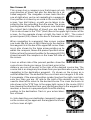
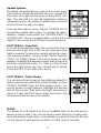
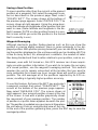
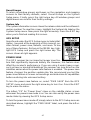
Satellite Status Screen
This screen appears each time you turn the unit on. It shows a graphical
view of the satellites that are in view. Each satellite is shown on the circu-
lar chart relative to your position. The point in the cen-
ter of the chart is directly overhead. The small inner
ring represents 45° above the horizon and the large
ring represents the horizon. North is at the top of the
screen. You can use this to see which satellites are
obstructed by obstacles in your immediate area if you
hold the unit facing north.
The GPS receiver is tracking satellites that are sur-
rounded by a black box. If the satellite number is not
surrounded by a box, then the receiver hasn’t locked
onto that satellite and it isn’t being used to solve the position.
Beneath the circular graph are the bar graphs, one for each satellite in
view. Although the unit has twelve channels, it dedicates one channel per
visible satellite. Therefore, if only six satellites are visible, only six bar
charts show at the bottom of the screen. The higher the bar on the graph,
the better the unit is receiving the signals from the satellite.
The number in the upper left corner is the “expected horizontal position
error” or expected error from a benchmark location. In other words, if the
expected error shows 50 feet, then the position shown by the unit is esti-
mated to be within 50 feet of the actual location. Although the expected

5
error is only an estimate, it does give you an indicator of the fix quality the
unit currently has. The smaller the expected error number, the better (and
more accurate) the fix is.
If the expected error is flashing, then the unit has not locked onto the
satellites, and the number shown is not valid.
The fix indicator on the left center shows either 2D or 3D. A 2D fix means
the unit has locked onto three satellites and has calculated its position. A
3D fix means the unit has locked onto at least four satellites and has
calculated both the position and altitude. (Remember, it takes three satel-
lites to determine the position - four to determine position and altitude.) If
neither 2D nor 3D are showing, then the unit doesn’t have the position or
altitude.
A battery level indicator on the lower right side of the screen shows ap-
proximately how much life is in the batteries. This runs from “F” (fully
charged) to “E” (expired).
A light bulb indicator at the top right corner of the screen appears when
the backlights are on.
Finding Your Position
Auto Search
To lock onto the satellites, the GPS receiver needs to know it’s current
position, local time, and date. (Elevation (altitude) is also used in the equa-
tion, but it’s rarely required to determine a position.) It needs this data so
that it can calculate which satellites should be in view. It then searches for
only those satellites. When your GPS receiver is turned on for the first
time, it doesn’t know what your position or elevation (altitude) is. It does
know the current UTC time and date since these were programmed into it
at the factory and an internal clock keeps the time while the unit is turned
off. It begins searching for the satellites using the above data that it ac-
quired the last time it was turned on. This probably was at the Lowrance
factory. Since it’s almost certain that you’re not at the Lowrance factory,
it’s probably looking for the wrong satellites. If it doesn’t find the satellites
it’s looking for after five minutes, it switches to Auto Search. The receiver
looks for any satellite in the sky. Due to advanced technology, the auto
search time has shrunk to about five minutes, so the longest time you
should ever have to wait is ten minutes from the time you turn the unit on
until it locks onto the satellites and shows a position. Once the unit locks
onto the satellites, it should take less than a minute to find your position
the next time it’s turned on, provided you haven’t moved more than ap-
proximately 100 miles from the last location it was used.

6
Manual Initialization
If you don’t want to wait for the Auto Search, then you may be able to
speed up the initialization process by using the manual initialization fea-
ture. Using this feature tells the unit it’s approximate position. Once it knows
it’s location, it determines exactly which satellites should be in view and
starts looking only for those satellites.
To manually initialize the unit, press the MENU key. Now press the down
arrow key until the “GPS SETUP” label is highlighted.
Press the right arrow key. The “INIT GPS” (Initialize
GPS) label is highlighted. Press the right arrow key
again. The screen at right appears. Use the arrow keys
to move the crosshairs to your approximate location
on the map. You may use the ZOUT key to zoom the
map out. This will make it easier and faster to find your
location on the map. Once you have the crosshairs on
your location, press the ENT key. The unit returns to
the satellite status screen.
Using the manual initialization method loads a position
that’s close to yours into the GPS receiver. It should now have position,
time, and date, thereby giving it the data it needs to determine which
satellites are in view. Once the satellites are known, the receiver searches
for only those satellites, making a lock faster than an auto search method.
Position Acquisition
When the receiver locks onto the satellites and calculates a position, it
shows the message “Position Acquired” on the screen. All position and
navigation data flashes until the unit acquires a position.
Do not rely on
any data that is flashing!
When the numbers are flashing, they represent
the last known values when the unit lost it’s lock on the satellites.
(Note: The altitude data may still flash even if the unit shows a “Position
Acquired” message and all other data is not flashing. The unit must be
locked onto at least four satellites to determine altitude. It only takes three
satellites to determine position. You can navigate with this unit if the alti-
tude is flashing, simply ignore the altitude display until it quits flashing.)
REMEMBER, DO NOT NAVIGATE WITH THIS UNIT UNTIL THE
NUMBERS STOP FLASHING!
Once the unit has acquired the satellites and is showing a fix on the sta-
tus screen, or the position acquired message appears, it’s ready for use.

7
POSITION/NAVIGATION SCREENS
This unit has four modes: status, map, navigation, and window groups.
Use the PAGES and arrow keys to switch between the different screens.
The four screens that show by default are shown below.
To change modes, simply press the PAGES key. A
screen similar to the one at right appears. Use the up
or down arrow keys to change modes. (The windows
mode is shown as “groups”. Group “A” is the first win-
dows group.)
Press the right arrow key while the above menu is show-
ing to switch between different versions of each mode.
When the desired screen appears, press the EXIT key
to erase the menu.
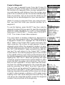
Navigation Screens
There are two different navigation
screens. Nav screen number one
shows a graphical view of your trip,
Nav screen number 2 shows all
navigation details in large digital
numbers. You can also customize
both navigation screens to show
data other than the default. See the
“Programming Boxes” section for
more information.
STATUS NAVIGATION MAP WINDOWS
NAV-1 NAV-2

8
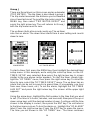
Nav Screen #1
This screen has a compass rose that shows not only
your direction of travel, but also the direction to a re-
called waypoint. The navigation screen looks like the
one at right when you’re
not
navigating to a waypoint.
Your position is shown by an arrow in the center of the
screen. Your trail history, or path you’ve taken is de-
picted by the line extending from the arrow. The arrow
pointing down at the top of the compass rose indicates
the current track (direction of travel) you are taking.
This is also shown in the “TRK” (track) box in the upper right corner of the
screen. On the example shown at right, the track is 355°. The current
ground speed (GS) shows in the box in the lower center of this screen.
When navigating to a waypoint, Nav screen number
one looks like the one at right. Bearing to the destina-
tion waypoint is in the box in the upper left corner. Bear-
ing is also shown by the large arrow pointing up to-
wards the compass, above the present position arrow.
Distance from the present position to the waypoint (DIS)
shows beneath the compass on the lower left side of
the screen.
Lines on either side of the present position show the
current cross track error range. Cross track error is the
distance you are off-course to the side of the desired course line. The
course line is an imaginary line drawn from your position when you started
navigating to the destination waypoint. It’s shown on the screen as a
vertical dotted line. The default for the cross track error range is 0.25 mile.
For example, if the present position symbol touches the right cross track
error line, then you are .25 mile to the right of the desired course. You
need to steer left to return to the desired course. The cross track error is
also shown in the “XTK” box. In the upper right corner is the course (CRS)
box showing the direction from your starting position to the waypoint. Re-
member, a course is a proposed path from the starting
position to the destination. Track is your actual direc-
tion of travel.
A circle depicting your destination (waypoint) appears
on the screen as you approach the waypoint as shown
on the screen at right.

9
Nav Screen #2
This navigation screen shows all navigation informa-
tion in large digital numbers. To view this screen, press
the PAGES key, then select the “NAV1” label. While it’s
selected, press the right arrow key. The screen shown
at right appears. Press the EXIT key to erase the menu.
This screen is composed of eight digital boxes. Track
(TRK) and ground speed (GS) data are all that show if
you’re not navigating to a waypoint. If you are navigat-
ing to a waypoint, then bearing (BRG), distance to waypoint (DIS), esti-
mated time en route (ETE), cross track error (XTK), destination arrow,
and the CDI also show.
The destination arrow shows the direction to the destination when the top
of the screen is pointing in your direction of travel.
Course Deviation Indicator (CDI)
Once navigation to a waypoint is established, the CDI
shows your distance to the left or right of the desired
course. The vertical line in the box shows both the di-
rection you must steer to get back on course and the
distance to the course line. For example, if you’re trav-
elling straight towards the destination, from the start, then the line stays in
the center. If you drift off course to the right, the line moves to the
left
. This
signifies that you need to steer to the left to get back on course. This is
called “chasing the needle”. If you steer towards the line (needle), you’ll
always be heading in the correct direction to get back on course.
The CDI’s range shows beneath the CDI label. On the above screen, the
CDI range is .20 mile, which is the default. You can adjust the range by
selecting the “ALARMS/CDI” label on the main menu. This is also shown
by the dotted lines at the far left and right side of the CDI. If the solid line
is on either of the dotted lines, then you are 0.20 mile off course. Remem-
ber, if the line moves to the left, then you are too far to
the right of the desired course line and vice-versa.
Using the CDI with a mapping screen helps you visu-
alize your position in relation to the course. This screen
shows that we are off course to the right. The vertical
bar has moved to the left side of the CDI, showing the
direction to the desired course line. The CDI gives you
a quick, visual indicator of your relationship between
your direction of travel and the destination.

10
Map
The GlobalMap 100 has a ground map of the world built inside. This map
has the majority of its detail in far southern Canada,
the continental United States and Hawaiian islands,
northern Mexico, the Bahamas, and Bermuda. The map
screens show your course and track from a “birds-eye”
view. If you’re navigating to a waypoint, the map shows
your starting location, present position, course line, and
destination. You don’t have to navigate to a waypoint,
however, to use the map.
Using the map is as simple as pressing the PAGES
key, then highlighting “MAP 1”. A screen similar to the
one at right appears. The arrow flashing in the center
of the screen is your present position. It points in the direction you’re trav-
elling. The solid line extending from the arrow is your plot trail, or path
you’ve taken. The plotter’s range shows in the lower left corner of the
screen. In this example, the plotter’s range is two miles from the left edge
of the screen to the right.
There are three different mapping screens. To view the other map screens,
press the PAGES key, highlight the MAP label, and press the right arrow
key until the desired map screen appears. Press the EXIT key to erase
the menu. Map-2 (shown below) has navigation data added at the bottom
of the screen, beneath the map. The data includes bearing to waypoint
(BRG), track (TRK), and distance to waypoint (DIS).
MAP-1
MAP-2 MAP-3
Map-3 is similar to Map-2. It shows ground speed (GS), track (TRK), and
the CDI at the bottom of the screen.
The Z-IN and Z-OUT keys zoom-in and out all maps to enlarge or reduce
their coverage area. The available ranges are: 0.1, 0.15, 0.2, 0.3, 0.4, 0.6,
0.8, 1, 1.5, 2, 3, 4, 5, 6, 8, 10, 15, 20, 30, 40, 60, 80, 100, 150, 200, 300,
400, 600, 800, 1000, 1500, and 2000 miles.

11
Cursor
Pressing an arrow key turns on two dotted lines that
intersect at the present position symbol. These lines
are called a “cursor” and have a variety of uses.
To turn the cursor on, simply press the arrow key in the
direction you want the cursor to move. This lets you
view areas on the plotter that are away from your
present position. The zoom-in and zoom-out keys work
from the cursor’s position when it’s active - not the
present position. You can zoom in on any detail, any-
where. The cursor can also place icons and waypoints.
Press the EXIT key to erase the cursor. The unit centers your present
position on the screen after erasing the cursor.
Map Setup
The map has many customization options. To change
them, first press the MENU key while a map is showing
on the screen. The map setup screen is highlighted.
Press the right arrow key. A screen similar to the one
at right appears.
Change Maps
Changes made to the map using the options in the
Map Setup is normally made to all map screens. The
change can be limited to the map screen currently in use, however, by
switching the “All Maps” to “This Map” in the “Change” menu. To do this,
simply highlight the “Change” label, then press the right arrow key. To
switch back, repeat the above.
Map Options
The following map options are listed under the “Map
Options” menu: Map Orientation, Auto Zoom, View
Destination, Range Rings, and Grids.
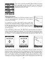
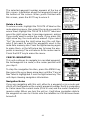
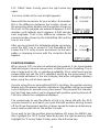
Map Orientation
By default, this receiver shows the map with north al-
ways at the top of the screen. This is the way most
maps and charts are printed on paper. This is fine if
you’re always travelling due north. What you see to your
left corresponds to the left side of the map, to your right is shown on the
right side of the map, and so on. However, if you travel any other direction,
the map doesn’t line up with your view of the world.

12
To correct this problem, a track-up mode rotates the map as you turn.
Thus, what you see on the left side of the screen should always be to your
left, and so on. A course-up mode keeps the map at the same orientation
as the initial bearing to the waypoint.
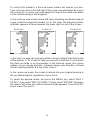
In the north-up view shown below left, we're travelling southeast towards
camp, saved as waypoint number 14. In this view, the present position
indicator appears to move towards the lower right corner of the screen.
In the track-up view, the present position moves straight towards the top
of the display. A "N" shows to help you see which direction is north when
the track-up mode is on. Remember, in the track-up mode, the screen
rotates as you change direction. It always keeps your direction of travel
(track) heading towards the top of the screen.
In the course-up mode, the screen is locked into your original bearing to
the recalled waypoint, regardless of your track.
To select the desired mode, first press the MENU key, select “MAP 1
SETUP”, then select “MAP OPTIONS”. Finally, select “ROTATE” and press
the right or left arrow key until the desired mode appears. Press the EXIT
key to erase this menu.
NORTH-UP TRACK-UP
COURSE-UP

13
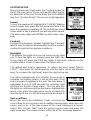
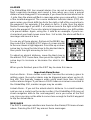
AUTOZOOM
This receiver has an autozoom feature that eliminates much of the button
pushing that competitive units force you to make. It works in conjunction
with the navigation features. First, recall a waypoint. (See the waypoint
section for more information on navigating to a waypoint.) Then, with the
autozoom mode on, the unit zooms out until the entire course shows,
from the present position to the destination waypoint (recalled waypoint).
As you travel towards the destination, the unit automatically begins zoom-
ing in, one zoom range at a time, keeping the destination on the screen.
The screens below show a slice of the progression of a trip near a lake.
Screen number one is the start and is on the 6 mile range. Intermediate
stages progressively zoom in as it gets closer to the destination.
123
456
To use the autozoom feature, first press the MENU key, select “Map 1
Setup”, then “Map Options”. Highlight “Auto Zoom”, then press the right
arrow key to turn it on. Press the EXIT key repeatedly to erase the menus.

14
EARTH MAP OPTIONS
The earth map consists of the built-in background map
of the world. To change the Earth map options, first
press the MENU key, then select the Earth Map label.
Press the right arrow key. The screen shown at right
appears.
Earth Map On/Off
The background map can be turned on or off using the
“Earth Map” menu. The earth map is the background
map that shows on the map screens. Simply highlight
the menu, then press the left arrow key to turn it off.
EARTH MAP ON
EARTH MAP OFF
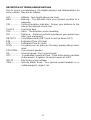
Range Rings/Grid Lines
The map screen can be customized with rings that are 1/4 of the range
and/or grids that divide the plotter into equal segments of latitude and
longitude. To do this, press the MENU key, select “Map 1 Setup”, then
“Map Options”. Highlight the desired option, then press the right arrow
key to turn it on. Press the EXIT key repeatedly to erase the menus. A
sample screen of each type shows below.
RANGE RINGS GRID BOTH RINGS & GRID
Page is loading ...
Page is loading ...
Page is loading ...
Page is loading ...
Page is loading ...
Page is loading ...
Page is loading ...
Page is loading ...
Page is loading ...
Page is loading ...
Page is loading ...
Page is loading ...
Page is loading ...
Page is loading ...
Page is loading ...
Page is loading ...
Page is loading ...
Page is loading ...
Page is loading ...
Page is loading ...
Page is loading ...
Page is loading ...
Page is loading ...
Page is loading ...
Page is loading ...
Page is loading ...
Page is loading ...
Page is loading ...
Page is loading ...
Page is loading ...
Page is loading ...
Page is loading ...
Page is loading ...
Page is loading ...
Page is loading ...
Page is loading ...
Page is loading ...
Page is loading ...
Page is loading ...
Page is loading ...
Page is loading ...
Page is loading ...
Page is loading ...
Page is loading ...
Page is loading ...
Page is loading ...
Page is loading ...
Page is loading ...
Page is loading ...
Page is loading ...
Page is loading ...
Page is loading ...
-
 1
1
-
 2
2
-
 3
3
-
 4
4
-
 5
5
-
 6
6
-
 7
7
-
 8
8
-
 9
9
-
 10
10
-
 11
11
-
 12
12
-
 13
13
-
 14
14
-
 15
15
-
 16
16
-
 17
17
-
 18
18
-
 19
19
-
 20
20
-
 21
21
-
 22
22
-
 23
23
-
 24
24
-
 25
25
-
 26
26
-
 27
27
-
 28
28
-
 29
29
-
 30
30
-
 31
31
-
 32
32
-
 33
33
-
 34
34
-
 35
35
-
 36
36
-
 37
37
-
 38
38
-
 39
39
-
 40
40
-
 41
41
-
 42
42
-
 43
43
-
 44
44
-
 45
45
-
 46
46
-
 47
47
-
 48
48
-
 49
49
-
 50
50
-
 51
51
-
 52
52
-
 53
53
-
 54
54
-
 55
55
-
 56
56
-
 57
57
-
 58
58
-
 59
59
-
 60
60
-
 61
61
-
 62
62
-
 63
63
-
 64
64
-
 65
65
-
 66
66
-
 67
67
-
 68
68
-
 69
69
-
 70
70
-
 71
71
-
 72
72


Lowrance GlobalMap 100 User manual
- Category
- Navigators
- Type
- User manual
Ask a question and I''ll find the answer in the document
Finding information in a document is now easier with AI
Related papers
-
Lowrance LMS-160 User manual
-
-
-
-
-
-
-
-
-
Other documents
-
Eagle MAPGUIDE - ADDENDUM Installation And Operation Instructions Manual
-
-
Lowrance electronic GlobalMap 12 User manual
-
-
-
-
-
-
-
Garmin GPS 12CX™ User manual