Land Pride AFM4214 User manual
- Category
- Garden tools
- Type
- User manual
This manual is also suitable for

Cover photo may show optional equipment
not supplied with standard unit.
© Copyright 2008 Printed
Read the Operator’s manual entirely. When
you see this symbol, the subsequent
instructions andwarnings are serious - follow
without exception. Your life and the lives of
others depend on it!
!
Table of Contents
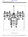
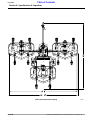
AFM4214 and AFM4216
All-Flex Grooming Mowers
315-587M
Operator’s Manual
11/14/08
25929

Table of Contents
AFM4214 and AFM4216 All-Flex Grooming Mowers 315-587M
11/14/08
Land Pride
Table of Contents
© Copyright 2008 All rights Reserved
Land Pride provides this publication “as is” without warrantyof any kind, eitherexpressedor implied.While every precautionhas beentaken in the preparation ofthis manual, Land
Pride assumesnoresponsibilityfor errorsoromissions.Neitheris anyliabilityassumed fordamagesresultingfromthe use oftheinformation containedherein. Land Pride reserves
the rightto reviseandimprove itsproductsas it seesfit.This publicationdescribes thestateof this productatthe time ofitspublication,andmay notreflect the productinthefuture.
Land Pride is aregistered trademark.
All other brands and product names are trademarks or registered trademarks oftheir respective holders.
Printed in the United States of America.
Important Safety Information . . . . . . . . . . .1
Safety at All Times . . . . . . . . . . . . . . . . . . . . . . . . . 1
Look For The Safety Alert Symbol . . . . . . . . . . . . .1
Safety Labels . . . . . . . . . . . . . . . . . . . . . . . . . . . . . 4
Introduction . . . . . . . . . . . . . . . . . . . . . . .11
Application . . . . . . . . . . . . . . . . . . . . . . . . . . . . . . 11
Using This Manual . . . . . . . . . . . . . . . . . . . . . . . . 11
Terminology . . . . . . . . . . . . . . . . . . . . . . . . . . 11
Definitions . . . . . . . . . . . . . . . . . . . . . . . . . . . . 11
Owner Assistance . . . . . . . . . . . . . . . . . . . . . . . . 11
Serial Number Plate . . . . . . . . . . . . . . . . . . . . 11
Section 1: Assembly and Set-up . . . . . .13
Tractor Requirements . . . . . . . . . . . . . . . . . . . . . 13
Hardware Torque Information . . . . . . . . . . . . . . . 13
PTO To Drawbar Set-Up . . . . . . . . . . . . . . . . . . . 13
Tractor Hook-up . . . . . . . . . . . . . . . . . . . . . . . . . . 13
Main Driveline Installation . . . . . . . . . . . . . . . . . . 14
Check Constant Velocity Driveline Length . . .14
Hydraulic Hook-up . . . . . . . . . . . . . . . . . . . . . . . . 15
Pull Rope Hook-up . . . . . . . . . . . . . . . . . . . . . . . . 15
Gauge Wheel Assembly . . . . . . . . . . . . . . . . . . . 15
Bleeding The Fold Hydraulics . . . . . . . . . . . . .16
Section 2: Operating Instructions . . . . .17
Introduction . . . . . . . . . . . . . . . . . . . . . . . . . . . . . 17
U-Joint Timing . . . . . . . . . . . . . . . . . . . . . . . . . . . 17
Transporting . . . . . . . . . . . . . . . . . . . . . . . . . . . . 17
Constant Velocity Driveline Angle . . . . . . . . . . . . 18
Pre-Operation Instructions . . . . . . . . . . . . . . . . . . 18
Operating Instructions . . . . . . . . . . . . . . . . . . . . . 19
General Operating Instructions . . . . . . . . . . . . . .20
Section 3: Adjustments . . . . . . . . . . . . . .21
Deck Height Adjustments . . . . . . . . . . . . . . . . . . .21
Belt Tension . . . . . . . . . . . . . . . . . . . . . . . . . . . . . 22
Section 4: Accessories . . . . . . . . . . . . . .23
Ball Swivel Hitch . . . . . . . . . . . . . . . . . . . . . . . . . 23
Cutting Blades . . . . . . . . . . . . . . . . . . . . . . . . . . . 23
Low Lift Blades (Standard) . . . . . . . . . . . . . . . 23
Medium Lift Blades . . . . . . . . . . . . . . . . . . . . . 23
High Lift Blades . . . . . . . . . . . . . . . . . . . . . . . . 23
Mulching Blades . . . . . . . . . . . . . . . . . . . . . . . 23
Section 5: Maintenance and Lubrication 24
Maintenance . . . . . . . . . . . . . . . . . . . . . . . . . . . .24
Servicing Mower Blades . . . . . . . . . . . . . . . . . . . .24
Blade Inspection . . . . . . . . . . . . . . . . . . . . . . .24
Blade Removal And Installation . . . . . . . . . . . .25
Blade Sharpening . . . . . . . . . . . . . . . . . . . . . .26
Blade Options: . . . . . . . . . . . . . . . . . . . . . . . . .26
V-Belt Installation . . . . . . . . . . . . . . . . . . . . . .26
Driveline Protection . . . . . . . . . . . . . . . . . . . . . . .27
Type A Clutches . . . . . . . . . . . . . . . . . . . . . . .27
Type B Clutch . . . . . . . . . . . . . . . . . . . . . . . . .29
Storage . . . . . . . . . . . . . . . . . . . . . . . . . . . . . . . .30
Tires With Air Pressure . . . . . . . . . . . . . . . . . . . .30
Lubrication Points . . . . . . . . . . . . . . . . . . . . . . . .31
Driveline Constant Velocity Shaft . . . . . . . . . .31
Driveline Shafts . . . . . . . . . . . . . . . . . . . . . . . .31
Inner Tube of Driveline . . . . . . . . . . . . . . . . . .31
Wheel Support Bushings . . . . . . . . . . . . . . . . .32
Wheel Bushings (Gauge Wheels) . . . . . . . . . .32
Wheel Bushings (Transport Hubs) . . . . . . . . . .32
Blade Spindle Bearings . . . . . . . . . . . . . . . . . .33
4-Way Gearbox . . . . . . . . . . . . . . . . . . . . . . . .33
Mower Deck Gearbox . . . . . . . . . . . . . . . . . . .33
Tool Bar to Deck Pivot Pin . . . . . . . . . . . . . . . .34
Transport Locks . . . . . . . . . . . . . . . . . . . . . . . .34
Wing Deck Pivot Bushings . . . . . . . . . . . . . . .34
Rear Deck Pivot Half Clamps . . . . . . . . . . . . .35
Wing Flex Pivot Lugs . . . . . . . . . . . . . . . . . . . .35
Section 6: Specifications & Capacities .36
Section 7: Features & Benefits . . . . . . . .40
Section 8: Troubleshooting . . . . . . . . . .41
Section 9: Appendix . . . . . . . . . . . . . . . .43
Torque Values Chart . . . . . . . . . . . . . . . . . . . . . .43
Tire Inflation Chart . . . . . . . . . . . . . . . . . . . . . . . .43
Notes . . . . . . . . . . . . . . . . . . . . . . . . . . . . . . . . . .44
Warranty . . . . . . . . . . . . . . . . . . . . . . . . . . . . . . .45

1
Important Safety Information
11/14/08
AFM4214 and AFM4216 All-Flex Grooming Mowers 315-587M
Land Pride
Table of Contents
Important Safety Information
These are common practices that may or may not be applicable to the products described in
this manual.
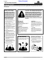
Safety at All Times
Thoroughly read and understand
the instructions given in this
manual before operation. Refer to
the “Safety Label” section, read
all instructions noted on them.
Do not allow anyone to operate
this equipment who has not fully
read and comprehended this
manual and who has not been
properly trained in the safe
operation of the equipment.
▲ Operator should be familiar with
all functions of the unit.
▲ Operate implement from the
driver’s seat only.
▲ Make sure all guards and shields
are in place and secured before
operating implement.
▲ Do not leave tractor or implement
unattended with engine running.
▲ Dismounting from a moving
tractor could cause serious injury
or death.
▲ Do not allow anyone to stand
between the tractor and
implement while backing up tothe
implement.
▲ Keep hands, feet, and clothing
away from power-driven parts.
▲ Wear snug fitting clothing to avoid
entanglement with moving parts.
▲ Watch out for wires, trees, etc.,
when raising implement. Make
sure all persons are clear of
working area.
▲ Turning tractor too tight may
cause implement to ride up on
wheels. This could result in injury
or equipment damage.
▲ Do not carry passengers on
implement at any time.
!
Look For The Safety Alert Symbol
The SAFETY ALERT SYMBOL indicates there is a
potential hazard to personal safety involved and extra
safety precaution must be taken. When you see this
symbol, be alert and carefully read the message that
follows it. In addition to design and configuration of
equipment, hazard control and accident prevention
are dependent upon the awareness, concern,
prudence and proper training of personnel involved in
the operation, transport, maintenance and storage of
equipment.
Be Aware of
Signal Words
A Signal word designates a degree or
level of hazard seriousness. The
signal words are:
Indicates an imminently hazardous
situation which, if not avoided, will
result in death or serious injury. This
signal word is limited to the most
extreme situations, typically for
machine components that, for
functional purposes, cannot be
guarded.
!
DANGER
Indicates a potentially hazardous
situation which, if not avoided, could
result in death or serious injury, and
includes hazards that are exposed
when guards areremoved. It may also
be used to alert against unsafe
practices.
Indicates a potentially hazardous
situation which, if not avoided, may
result in minor or moderate injury. It
may also be used to alert against
unsafe practices.
!
WARNING
!
CAUTION
For Your Protection
▲ Thoroughly read and understand
the “SafetyLabel”section, read all
instructions noted on them.
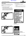
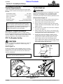
Shutdown and Storage
▲ Lower machine to ground, put
tractor in park, turn off engine, and
remove the key.
▲ Detach and store implements in a
area where children normally do
not play. Secure implement by
using blocks and supports.
OFF
REMO
VE

2
Important Safety Information
AFM4214 and AFM4216 All-Flex Grooming Mowers 315-587M
11/14/08
Land Pride
Table of Contents
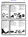
Transport
Machinery Safely
▲ Comply with state and local laws.
▲ Maximum transport speed for
implement is 20 mph. DO NOT
EXCEED. Never travel at a speed
which does not allow adequate
control of steering and stopping.
Some rough terrain require a
slower speed.
▲ Sudden braking can cause a
towed load to swerve and upset.
Reduce speed if towed load is not
equipped with brakes.
▲ Use the following maximum
speed - tow load weight ratios as
a guideline:
20 mph when weight is less
than or equal to the weight of
tractor.
10 mph when weight is double
the weight of tractor.
▲ IMPORTANT: Do not tow a load
that is more than double the
weight of tractor.
Use Safety
Lights and Devices
▲ Slow moving tractors, self-
propelled equipment, and towed
implements can create a hazard
whendrivenonpublicroads. They
are difficult to see, especially at
night.
▲ Flashing warning lights and turn
signals are recommended
whenever driving on public roads.
Practice Safe
Maintenance
▲ Understand procedure before
doing work. Use proper tools and
equipment, refer to Operator’s
Manual for additional information.
▲ Work in a clean dry area.
▲ Lower the implement to the
ground, put tractor in park, turn off
engine, and remove key before
performing maintenance.
▲ Allow implement to cool
completely.
▲ Do not grease or oil implement
while it is in operation.
▲ Inspect all parts. Make sure parts
are in good condition & installed
properly.
▲ Remove buildup of grease, oil or
debris.
▲ Remove all tools and unused
parts from implement before
operation.
Use A Safety Chain
▲ A safety chain will help control
drawn machinery should it
separate from the tractor
drawbar.
▲ Use a chain with the strength
rating equal to or greater than
the gross weight of the towed
machinery.
▲ Attach the chain to the tractor
drawbar support or other
specified anchor location. Allow
only enough slack in the chain
to permit turning.
▲ Do not use safety chain for
towing.
These are common practices that may or may not be applicable to the products described in
this manual.

3
Important Safety Information
11/14/08
AFM4214 and AFM4216 All-Flex Grooming Mowers 315-587M
Land Pride
Table of Contents
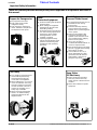
Prepare for Emergencies
▲ Be prepared if a fire starts.
▲ Keep a first aid kit and fire
extinguisher handy.
▲ Keep emergency numbers for
doctor, ambulance, hospital and
fire department near phone.
911
Wear
Protective Equipment
▲ Protectiveclothing and equipment
should be worn.
▲ Wear clothing and equipment
appropriate for the job. Avoid
loose fitting clothing.
▲ Prolonged exposure to loud noise
can cause hearing impairment or
hearing loss. Wear suitable
hearing protection such as
earmuffs or earplugs.
▲ Operating equipment safely
requires the full attention of the
operator. Avoid wearing radio
headphones while operating
machinery.
These are common practices that may or may not be applicable to the products described in
this manual.
Tire Safety
▲ Tire changing can be dangerous
and should be performed by
trained personnel using the
correct tools and equipment.
▲ When inflating tires, use a clip-on
chuck and extension hose long
enough to allow you to stand to
one side and NOT in front of or
over the tire assembly. Use a
safety cage if available.
▲ When removing and installing
wheels, use wheel handling
equipment adequate for the
weight involved.
Keep Riders
Off Machinery
▲ Riders obstruct the operator’s
view, they could be struck by
foreign objects or thrown from the
machine.
▲ Never allow children to operate
equipment.
Avoid High
Pressure Fluids Hazard
▲ Escaping fluid underpressurecan
penetrate the skin causing
serious injury.
▲ Avoid the hazard by relieving
pressure before disconnecting
hydraulic lines or performing work
on the system.
▲ Make sure all hydraulic fluid
connections are tight and all
hydraulic hoses and lines are in
good condition before applying
pressure to the system.
▲ Use a piece of paper or
cardboard, NOT BODY PARTS, to
check for suspected leaks.
▲ Wear protective gloves and safety
glasses or goggles when working
with hydraulic systems.
▲ If an accident occurs, see a
doctor immediately. Any fluid
injected into the skin must be
treated within a few hours or
gangrene may result.

4
Important Safety Information
AFM4214 and AFM4216 All-Flex Grooming Mowers 315-587M
11/14/08
Land Pride
Table of Contents
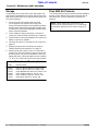
Safety Labels
Your All-Flex Mower comes equipped with all safety
labels in place. They were designed to help you safely
operate your implement. Read and follow their
directions.
1. Keep all safety labels clean and legible.
2. Replace all damaged or missing labels. To order new
labels go to your Land Pride dealer.
3. Some new equipment installed during repair requires
safety labels to be affixed to the replaced component as
specified by Land Pride. When ordering new components
make sure the correct safety labels are included in the
request. To order new labels go to your Land Pride dealer.
4. Refer to this section for proper label placement.
To install new labels:
a. Clean the area the label is to be placed.
b. Spray soapy water on the surface where the label is to
be placed.
c. Peel backing from label. Press firmly onto the surface.
d. Squeeze out air bubbles with the edge of a credit card.
818-339C
Warning: High Pressure
26563
26563
818-558C
Warning: Serious Injury


7
Important Safety Information
11/14/08
AFM4214 and AFM4216 All-Flex Grooming Mowers 315-587M
Land Pride
Table of Contents
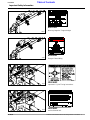
26566
818-556C
Danger: Thrown Object Hazard
Location: (3-Places) On Back of All Three Decks
26565
818-552C
Danger: Entanglement
ROTATING DRIVELINE
KEEP AWAY!
26566
818-555C
Danger: Rotating Blade
Location: (3-Places) On Back of All Three Decks
26566
818-045C
Warning: Pinch point or Crushing Hazard
Location: (3-Places) On Back of All Three Decks

8
Important Safety Information
AFM4214 and AFM4216 All-Flex Grooming Mowers 315-587M
11/14/08
Land Pride
Table of Contents
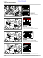
818-003C
Slow Moving Vehicle Label
Location: On Back of Center Deck Only
26566
26566
818-514C
Caution: V-Belt Installation
Location: (1-Place) Beneath Guard on Right Hand Deck
818-543C
Danger: Guard Missing
Location: (6-Places)
Beneath Both Guards on All Three Decks
26566
818-513C
Caution: V-Belt Installation
Location: (2-Places) Beneath Guard on
Center and Left Hand Decks

9
Important Safety Information
11/14/08
AFM4214 and AFM4216 All-Flex Grooming Mowers 315-587M
Land Pride
Table of Contents
26562
818-230C
Red Reflector
Location: 2-Places
(Large Arrows Back of Gearbox Mounts)
26561
818-229C
Amber Reflector
Location: Front of Wing Decks (Left Wing Shown)
26575
818-187C
Danger: Shield Missing
Location: Splitter Gearbox
818-335C
Red Reflector
Location: 4-Places
(Small Arrows Back of Deck)


11
Introduction
11/14/08
AFM4214 and AFM4216 All-Flex Grooming Mowers 315-587M
Land Pride
Table of Contents
Introduction
Definitions
Owner Assistance
The Warranty Registration card should be filled out by
the dealer at the time of purchase. This information is
necessary to provide you with quality customer service.
If customer service or repair parts are required contact a
LandPridedealer. Adealerhas trainedpersonnel,repair
parts and equipment needed to service the implement.
The parts on your All-Flex Mower have been specially
designedandshouldonlybereplacedwithgenuineLand
Pride parts. Therefore, should your All-Flex Mower
require replacement parts go to your Land Pride Dealer.
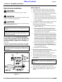
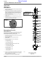
Serial Number Plate
For prompt service always use the serial number and
modelnumber when ordering partsfrom your Land Pride
dealer.Besuretoincludeyourserialandmodel numbers
incorrespondencealso.Referto Figure1 forthe location
of your serial number plate.
Serial Number Plate Location
Figure 1
NOTE: A special point of information that the
operator must be aware of before continuing.
IMPORTANT: Aspecial point of informationrelatedto
its preceding topic. Land Pride’s intention is that this
information should be read and noted before
continuing.
26563
Manual Storage Tube
Land Pride welcomes you to the growing family of new
product owners.
This AFM42 Series All-Flex Mower has been designed
with care and built by skilled workers using quality
materials. Proper assembly, maintenance, and safe
operating practices willhelpyou get years of satisfactory
use from the machine.
Application
The AFM4214 (14 foot) and AFM4216 (16 foot) All-Flex
Mowers are designed and built by Land Pride to provide
excellent cutting quality and performance on lush type
turf grasses that are located on expansive and well
manicured areas such as sports fields, theme parks,
fairways, turf farms, and large estates.
Theywilldeliverexcellentperformance whenattachedto
40-70 hp tractors with 540 rpm PTO speed and pull-type
draw bar. The hydraulic wing cylinders will easily lift up
the wing decks for a 6’-8" overall transport width when
moving from one site to another on public streets or on
right-of-ways.
The contour following capability, highly productive
cutting widths and rear discharge design of the floating
cutting decks will greatly reduce wide-area cutting times
and still deliver finely groomed surfaces at mowing
speeds from 2-6 mph. The AFM4214 and AFM4216
All-Flex Mower can be ordered with slip-clutch or
conventional wing driveline configurations and a choice
of 15 inch or 18 inch deck tires.
See “Section 6: Specifications & Capacities” and
“Section 7: Features & Benefits” for additional
information and performance enhancing options.
Using This Manual
•
This Operator’s Manual is designed to help familiarize
you with safety, assembly, operation, adjustments,
troubleshooting, and maintenance. Read this manual
and follow the recommendations to help ensure safe
and efficient operation.
• The information contained within this manual was
current at the time of printing. Some parts may change
slightly to assure you of the best performance.
• To order a new Operator’s or Parts Manual contact
your authorized dealer. Manuals can also be
downloaded, free-of-charge from our website at
www.landpride.com.
• Refer to Figure 1. Store your Operator’s Manual in the
dry storage tube for future reference.
Terminology
“Right” or “Left” as used in this manual is determined by
facing the direction the machine will operate while in use
unless otherwise stated.

12
Introduction
AFM4214 and AFM4216 All-Flex Grooming Mowers 315-587M
11/14/08
Land Pride
Table of Contents
Your dealer wants you to be satisfied with your new
machine. If for any reason you do not understand any
part of this manual or are not satisfied with the service
received, the following actions are suggested:
1. Discuss the matter with your dealership Service
Manager making sure he is aware of any problems
youmay have and that he has had the opportunity to
assist you.
2. If you are still not satisfied, seek out the Owner or
General Manager of the dealership, explain the
problem and request assistance.
3. For further assistance write to:
Land Pride Service Department
1525 East North Street
P.O. Box 5060
Salina, Ks. 67402-5060
E-mail address
lpser[email protected]

13
Section 1: Assembly and Set-up
11/14/08
AFM4214 and AFM4216 All-Flex Grooming Mowers 315-587M
Land Pride
Table of Contents
Section 1: Assembly and Set-up
Tractor Requirements
Tractor horsepower should be within the range noted
below. Tractors outside the horsepower range must not
be used.
Horsepower Rating. . . . . . . . . . . . . . . . . . . .40-70 HP
Rear PTO Shaft Type . . . . . . . . . . . . . .1 3/8”-6 Spline
Rear PTO Speed . . . . . . . . . . . . . . . . . . . . 540 RPM
Hitch Type . . . . . . . . . . . . . . . . . . . . . . . . . .Draw Bar
Hydraulic Outlets . . . . . . . . . . . . . One Duplex Outlet
Tractor Weight . . . . . . . . . See Important Note Below
Hardware Torque Information
When tightening hardware, refer to “Torque Values
Chart” on page 43 to determine standard torque values.
Refer to "Additional Torque Values" at the bottom of the
chart for exceptions to the standard torque values.
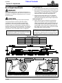
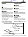
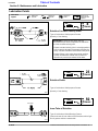
PTO To Drawbar Set-Up
!
CAUTION
Do not over speed PTO or machine damage may result. This
mower is designed to be used with a tractor using a rear
540 rpm PTO drive.
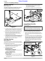
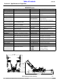
Refer to Figure 1-1:
Distances between center of drawbar hitch pin hole to
end of tractor PTO shaft (“A” dimension) and from top of
drawbar hitch to center of PTO shaft (“B” dimension)
must be maintained.
IMPORTANT: Ballast may need to be added to your
tractor to maintain steering control. Refer to your
tractor’s operator manual to determine if additional
ballastis needed.This mowerhasapositivetransport
tongue weight of approximately 540 lbs. on the
AFM4214 and 580 lbs. on the AFM4216.
IMPORTANT: PTO damage may occur if distances
“A” and “B” are not properly maintained.
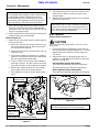
Tractor Hook-up
!
DANGER
Crushing Hazard between tractor and implement. Do not allow
anyone to stand between the tractor and implement while
backing-up to an implement. Never operate the hydraulic
3-point lift controlswhile someone is directly behind the tractor.
Refer to Refer to Figure 1-2:
1. Make certain jack stand is properly attached to the
mower hitch and secured with attachment pin.
2. Back tractor within close proximity of clevis.
3. Raise or lower jack stand to align clevis with tractor
drawbar. Drawbar should fit betweenlower and upper
plates of clevis.
4. Back tractor up to mower hitch until holes in drawbar
and clevis are aligned.
5. Attach mower with a 3/4" hitch pin and secure with
lockpin.Always usea hitch pin thatcontains a safety
locking device to prevent it from falling out.
6. Retract jack stand until weight of mower is fully
removed from the jack. Remove jack and store on
storage tube located on divider gearbox shield.
7. Attach safety chain on the frame tongue to the
tractor.Adjustchainlengthtoremoveallslackexcept
what is necessary to permit turning of mower. Lock
chain hook securely onto the chain.
PTO to Drawbar Distances
Figure 1-1
22273
= 8”
= 14”
Mower to Tractor Hook-up
Figure 1-2
14918

14
Section 1: Assembly and Set-up
AFM4214 and AFM4216 All-Flex Grooming Mowers 315-587M
11/14/08
Land Pride
Table of Contents
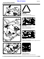
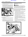
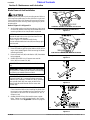
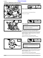
Refer to Figure 1-3
1. Place tractor gear selector in park, shut tractor
engine off, set park brake and remove switch key.
2. Attach driveline to mower and tractor as follows:
a. Slide inner yoke of driveline over mower gearbox
shaft and secure with locking collar.
b. Slide outer yoke with constant velocity joint over
tractor PTO shaft and secure with locking collar.
c. Skip to Step 4 if driveline fits between tractor and
Grooming Mower.
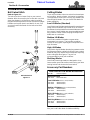
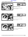
3. The driveline will require shortening if it is too long to
fit between the tractor and Grooming Mower.
Shorten driveline as follows:
a. Pull driveline profiles apart into two sections as
shown in Figure 1-3.
b. Attach outer driveline universal joint to tractor
PTO shaft and inner driveline universal joint to
gearboxshaft.Pull oneach driveline sectionto be
sure universal joints are secured.
c. Hold driveline sections parallel to each other to
determineiftheyaretoolong.Theinnerandouter
shieldsoneachsectionshouldendapproximately
1" short of reaching the universal joint shield on
the adjacent section (see “B” dimension). If they
are too long, measure 1" (“B” dimension) back
fromtheuniversaljointshield and make amark at
this location on the inner and outer shields.
d. Cut off inner shield at mark (“X” dimension). Cut
same amount off inner shaft (“X1” dimension).
Repeat cut off procedure (“Y”&“Y1” dimensions)
to cut outer driveline half.
e. Remove all burrs and cuttings.
4. With driveline profiles pulled apart, apply
multi-purpose greasetotheinsideof theouterprofile
and then reassemble the two profiles.
5. Attach inner driveline yoke to gearbox shaft and
outer driveline yoke to tractor's PTO shaft.
6. Thedrivelineshould nowbe movedbackand forthto
insurethatboth ends are secured. Reattach any end
that is loose.
7. Hook a safety chain in the hole on the outer driveline
yoke shield and its opposite end to the tractor.
8. Hook the other safety chain in the hole on the inner
driveline yoke shield and its opposite end to the
mower.
IMPORTANT: Two small chains supplied with the
driveline must be attached to restrict driveline shield
rotation.
Main Driveline Installation
!
WARNING
Damaged drivelines can cause serious injury or death.
!
CAUTION
Tractor PTO shield and all Grooming Mower guards must be
in place at all times during operation!
!
CAUTION
Always engage parking brake, shut off tractor and remove key
before dismounting from tractor.
Always engage PTO at low engine rpm to minimize
start-up torque on driveline. Drivelines with friction
clutches must go through a “run-in” operation prior
to initial use and after long periods of inactivity. See
“Driveline Protection” on page 27” for a detailed run-in
description.
Check Constant Velocity Driveline Length
Driveline Shortening
Figure 1-3
IMPORTANT: The drivelinemustbelubricatedbefore
putting it into service. Refer to “Lubrication Points” on
page 31.
IMPORTANT: Some tractors are equipped with
multispeed PTO ranges. Be certain your tractor ‘s
PTO is set for 540 rpm.
IMPORTANT: Always check driveline length during
initialsetupand whenconnectingto adifferenttractor.
Too long a driveline can damage tractor, gearbox and
the driveline.
23557

15
Section 1: Assembly and Set-up
11/14/08
AFM4214 and AFM4216 All-Flex Grooming Mowers 315-587M
Land Pride
Table of Contents
d. Hold locks in this position until all 3 mower decks
have unfolded enough to allow lock lugs to
become fully disengaged.
e. Extend all 3 cylinders to their maximum stroke.
Pull Ropes
Figure 1-5
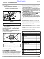
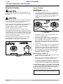
Gauge Wheel Assembly
Refer to Figure 1-6:
Center deck gauge wheels (#4) are mounted in the
carrier frames spindle support tubes upside down.
1. Remove nuts (#7) and bolts (#6) from the center
deck carrier frames and remove gauge wheels from
the frames.
2. Check spacer location on the other gauge wheels.
Note how manyand what sizes are above and below
thegaugewheelspindlesupporttubeandthenplace
an equal number of spacers (#1, 2 & 3) and sizes
above and below the spindle support tube while
inserting the gauge wheel spindle into the spindle
support tubes.
Center Deck Rear Gauge Wheels
Figure 1-6
13660
Spring Loaded
Transport Locks
1
IMPORTANT: Do not bend spring steel mounting
bracket supporting the slow movingvehicle sign. This
sign is purposely angled so that when the deck is
folded up for transporting, the sign will face traffic.
26620
Leave Slow Moving Vehicle Sign angled.
This sign should face traffic when deck
is folded up for transporting.
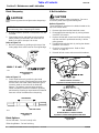
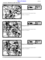
Hydraulic Hook-up
Refer to Figure 1-4:
This mower is equipped and plumbed from the factory
with double acting cylinders, hydraulic hoses and
couplings for folding the wings and center deck.
Hydraulic Hook-up
Figure 1-4
1. Cutplastic tiessecuringhydraulichoses(#1)to hose
support loop (#2). Be careful not to cut plastic tie
securing the ten linch pins (#5) to the support loop.
2. Route hoses (#1) through hose support loop (#2)
and connect to tractor remote outlets. Quick
disconnect hydraulic fittings for your tractor are
supplied attached to the hoses.
3. Locatecarbonsteelwire(#3)attachedbetweenwing
cylinders (#4). This wire secures the wing decks in
the folded position during shipment. Remove wire
and dispose of it in a trash container.
Pull Rope Hook-up
Refer to Figure 1-5:
The operator on the tractor seat will need to be able to
access the pull rope from the tractor seat when lowering
the folded decks to ground level.
1. Attach pull rope (#1) to an area within the operator’s
reach. Make sure the pull rope can not become
tangled with the operator and driveline.
2. Unfold mower decks as follows:
AFM4216 Model Only
Refer to Figure 2-3 on page 18:
a. If attached, remove wing deck floating pins and
store in storage tube (#2).
AFM4214 & AFM4216 Models
Refer to Figure 1-5:
b. Retracthydraulic cylinders to remove weight from
transport locks.
c. Pull transport lock rope (#1) toward the tractor to
disengage locks.
26622

16
Section 1: Assembly and Set-up
AFM4214 and AFM4216 All-Flex Grooming Mowers 315-587M
11/14/08
Land Pride
Table of Contents
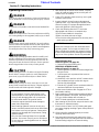
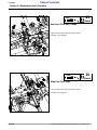
Transport Fold Hydraulic Plumbing
Figure 1-8
13658
3. Raise center deck up just enough to insert gauge
wheel spindles into the carrier framespindle support
tubes as shown in Figure 1-6.
4. Secure gauge wheels with linch pins (#8) supplied
attached to the support loop with plastic ties. Insert
linch pins from the front and flip clasp shut over the
spindles towards the back. Attaching linch pin in this
manner will prevent vegetation from catching on the
clasp and flipping it open while traveling forward.
Center Deck Rear Gauge Wheels
Figure 1-7
Refer to Figure 1-7:
5. Lower all mower decks fully down. Decks should be
supported by the gauge wheels with gauge wheels
on the ground.
6. Remove bolts (#6) from the remaining gauge wheel
spindles and replace with remaining linch pins (#8).
Insertlinchpinsfromthefrontandflipclaspshutover
the spindles towards the back.
26620
Bleeding The Fold Hydraulics
Refer to Figure 1-8:
!
DANGER
Hydraulic fluid under pressure can penetrate skin. Wear
protective gloves and safety glasses or goggles when working
with hydraulic systems. Use a piece of cardboard or wood
rather than hands when searching for hydraulic leaks. If
hydraulic fluid is injected into the skin, it must be treated by a
doctor within a few hours or gangrene may result.
Hydraulic hoses and cylinders are supplied fully charged
with oil from the factory and should not require bleeding.
If any ofthedecks raise or lower in ajerking motion, then
bleed the hydraulics as follows:
1. With mower decks lowered onto the ground, remove
connecting pins (#1) from rod end of the 2 wing
cylinders (#2) and center deck cylinder (#3).
2. Support cylinders vertically with rod end up.
3. Cyclehydraulicsystem toextendbothwingcylinders
and center deck cylinder. Retract cylinders and
repeat this process 2 times.
4. On each cylinder, crack rod end cylinder fitting (#4)
and apply hydraulic pressure until air free oil leaks
from fitting and then retighten fitting.
5. Support cylindersin averticalposition withbaseendof
cylinder up and repeat bleeding process on the base
end fitting (#5).
6. Re-pin all clevises. Secure pins with cotter pins (#6)
by bending one or more legs of the cotter pin.
7. Slowly cycle all decks to transport position checking
to make sure the hydraulic hoses are not pinched in
the process.

17
Section 2: Operating Instructions
11/14/08
AFM4214 and AFM4216 All-Flex Grooming Mowers 315-587M
Land Pride
Table of Contents
Transporting
!
WARNING
Do not transport mower faster than 20 mph. When traveling
on roadways, transport in such a manner that vehicles moving
at a faster rate of speed may pass you safely.
!
CAUTION
Care should be taken when encountering oncoming traffic and
roadside obstructions if the mower is wider than your tractor.
!
CAUTION
Always disengage tractor PTO before raising the Grooming
Mower to transport position to avoid damaging the mower,
injury from thrown objects or blade contact.
!
CAUTION
Whentravelingon public roads, whether at night orduringthe
day, use accessory lights and devices for adequate warning to
operatorsof other vehicles. Comply with all federal,state, and
local laws.
• Be sure to reduce tractor ground speed when turning;
and, leave enough clearance so the mower does not
contact obstacles such as buildings, trees or fences.
• Select a safe ground travel speed when transporting
from one area to another. When traveling on
roadways, transport in such a way that faster moving
vehicles may pass you safely.
• When traveling over rough or hilly terrain, shift tractor
to a lower gear.
Refer to Figure 2-2:
1. Raise the 3 mower decks to the transport position by
retracting all 3 cylinders completely.
2. As the mower decks are raising, the transport locks
(3 each) will automatically lock in place when
operating properly.
Pull Ropes
Figure 2-2
13660
Spring Loaded
Transport Locks
Pull Rope
Section 2: Operating Instructions
Introduction
Hazard control and accident prevention are dependent
upon the awareness, concern, prudence and proper
training involved in the operation, transport,
maintenance and storage of the Grooming Mower.
Therefore, it is absolutely essential that no one operates
themower without first having read,fully understood and
becometotallyfamiliarwiththeOperator’sManual.Make
sure the operator has paid particular attention to:
• Important Safety Information, pages 1 to 10
• Section 1: Assembly and Set-up, page 13
• Section 2: Operating Instructions, page 17
• Section 3: Adjustments, page 21
• Section 5: Maintenance and Lubrication, page 24
Hazard control and accident prevention are dependent
upon the awareness, concern, prudence and proper
training involved in the operation, transport,
maintenance and storage of the mower.
!
DANGER
Before making adjustments or performing maintenance on
your mower, disengage PTO, shut off tractor and wait for all
moving parts to stop before dismounting tractor. Disconnect
PTO driveline.
U-Joint Timing
Refer to Refer to Figure 2-1:
!
CAUTION
On mowers equipped without slip clutches the deck drivelines
(3 each) must be in time to avoid driveline damage when
folding - unfolding
.
U-Joint Timing
Figure 2-1
IMPORTANT: Do not alter the Grooming Mower in a
way which will adversely affect its performance or
reliability or use the mower for a purpose for which it
was not designed.

18
Section 2: Operating Instructions
AFM4214 and AFM4216 All-Flex Grooming Mowers 315-587M
11/14/08
Land Pride
Table of Contents
Refer to Figure 2-3:
3. AFM4216 models only. If narrow transport width is
required or if transporting long distances:
a. Insert 5/8” deck float pin (#1) in lock hole located
to the outside of both mower wing decks.
b. Make sure deck float pin is fully inserted.
Model AFM4216 Deck Float Pin
Figure 2-3
4. Referto “Operating Instructions” on page19 when
lowering the decks.
Constant Velocity Driveline Angle
Refer to Figure 2-4:
The main driveline is equipped with a constant velocity
(CV) joint that allows the unit to run at angles up to
80 degrees with no vibration.
Constant Velocity Driveline Angle
Figure 2-4
The constant velocity joint must be greased every 8
hours of operation. Refer to Page 31 “Driveline
Constant Velocity Shaft”.
Pre-Operation Instructions
Proper servicing and adjustments are key to the long life
of any machine. With careful and systematic inspection
of the mower, you can avoid costly maintenance, time
and repair. Before beginning to operate your All-Flex
Mower the following inspection should be performed.
26567
NOTE: Be sure to remove deck floating pins before
unfolding mower decks.
19626
IMPORTANT: Do not make turns that will subject the
CV joint to angles greater than 80
o
. Angles greater
than 80
o
will damage the driveline.
• Grease driveline shaft and all other grease fittings.
• Check oil level in gearboxes. Refer to the Lubrication
portion of the “Maintenance and Lubrication”
section starting on page 24.
• Check all plugs and caps in gearboxes to make certain
that they have been replaced and tightened properly.
• Check mower blades for sharpness and damage. See
“Blade Inspection” on page 24.
• Besurebladesareinstalledproperlyoneachdeckwith
the cutting edge leading in rotation. See “Blade
Removal And Installation” on page 25.
• Be sure all mower blade bolts are tight. Know which
centerbladeboltsarelefthandthreadedandwhichare
right hand threaded when checking for tightness. See
“Blade Removal And Installation” on page 25.
• Be sure all bolts and nuts are tight.
• Be certain all guards and shields are in place and
secure.
• Clear the area to be mowed of objects and debris that
might be picked up and thrown by the mower blades
• Operate with 540 rpm PTO tractor.
• Refer to your tractor’s operator manual for engaging
and disengaging the PTO.
• In case of emergency learn to stop tractor and mower
quickly.
• Complete Operating Check List below.
Operating Check List
✔
Check
Refer
Read and understand all Safety Rules. Page 1
Make sure all gearboxes are properly
lubricated.
Page 24
Read and follow proper tractor hook-up
procedure.
Page 13
Make sure all tires are properly inflated.
Page 43
Lubricate mower components as needed. Page 24
Check mower initially and periodically for
loose bolts & pins.
Make sure hitch safety chain is securely
attached to the mower hitch and tractor.
Page 13
Inspect cutting blades. Make note of blade
wear and sharpness.
Page 24
Make a thorough examination of the
drivelines. Also check connections to the
gearboxes and tractor PTO shaft.
Make sure all guards and shields are in
place.
Page is loading ...
Page is loading ...
Page is loading ...
Page is loading ...
Page is loading ...
Page is loading ...
Page is loading ...
Page is loading ...
Page is loading ...
Page is loading ...
Page is loading ...
Page is loading ...
Page is loading ...
Page is loading ...
Page is loading ...
Page is loading ...
Page is loading ...
Page is loading ...
Page is loading ...
Page is loading ...
Page is loading ...
Page is loading ...
Page is loading ...
Page is loading ...
Page is loading ...
Page is loading ...
Page is loading ...
Page is loading ...
-
 1
1
-
 2
2
-
 3
3
-
 4
4
-
 5
5
-
 6
6
-
 7
7
-
 8
8
-
 9
9
-
 10
10
-
 11
11
-
 12
12
-
 13
13
-
 14
14
-
 15
15
-
 16
16
-
 17
17
-
 18
18
-
 19
19
-
 20
20
-
 21
21
-
 22
22
-
 23
23
-
 24
24
-
 25
25
-
 26
26
-
 27
27
-
 28
28
-
 29
29
-
 30
30
-
 31
31
-
 32
32
-
 33
33
-
 34
34
-
 35
35
-
 36
36
-
 37
37
-
 38
38
-
 39
39
-
 40
40
-
 41
41
-
 42
42
-
 43
43
-
 44
44
-
 45
45
-
 46
46
-
 47
47
-
 48
48


Land Pride AFM4214 User manual
- Category
- Garden tools
- Type
- User manual
- This manual is also suitable for
Ask a question and I''ll find the answer in the document
Finding information in a document is now easier with AI
Related papers
-
 Land Pride AFM4214 All-Flex User manual
-
 Land Pride Brush Cutter RC 55 User manual
-
 Land Pride RC 55 User manual
-
 Land Pride AFM4522 User manual
-
 Land Pride AFM4214 Series User manual
-
 Land Pride FD2548 User manual
-
 Land Pride AFM4014 User manual
-
 Land Pride FD1560 User manual
-
 Land Pride FDR16 User manual
-
 Land Pride FD2560 User manual


Other documents
-
Braber Equipment BE-FM84RDHDG User manual
-
 Progressive Turf Equipment Pro-Max 36 16371000 to Current User manual
-
 Progressive Turf Equipment Pro-Flex 120 17272407 To Current User manual
-
Toro Deck Reinforcement Kit, for ProLine 42" Cutting Unit Installation guide
-
Ransomes 78136 Owner's manual
-
Grizzly T28930 Owner's manual
-
Progressive Turf Equipment SDR-65 15365073 To Current User manual
-
 Kunz C60K User manual
-
 Kunz MR44K User manual
-
 MacDon R113 & R116 Unloading & Assembly Instruction


