Page is loading ...

STOP! TO PREVENT DAMAGING YOUR GRILL,
READ THIS MANUAL FIRST FOR IMPORTANT UNPACKING AND
ASSEMBLY INSTRUCTIONS!
Type OG02 Gas Grill
Assembly and Operation Manual
Consumer Affairs: 1-800-851-8900
FOR OUTDOOR USE ONLY
Hamilton Beach Brands, Inc.
Glen Allen, Virginia 23060
840232800

TABLE OF CONTENTS
BEFORE YOU BEGIN
Message to Our Users ................................................................................................................... 3
Safety Symbols .............................................................................................................................. 3
Installation/Safety Precautions ...................................................................................................... 4
Propane and Gas Warning ............................................................................................................ 4
ASSEMBLY
Before the Assembly ... ............................................................................................................... 5
Assembly Steps ........................................................................................................................ 9
POST-ASSEMBLY
Gas Connection ........................................................................................................................... 23
Leak Testing ................................................................................................................................. 26
Final Installation Checklist ........................................................................................................... 27
Grill Lighting Instructions .............................................................................................................. 27
Operating Instruction..................................................................................................................... 29
Safety Tips ... ................................................................................................................................ 31
Care and Maintenance ................................................................................................................ 31
Troubleshooting ........................................................................................................................... 33
Food Safety .................................................................................................................................. 34
Grill Storage ... .............................................................................................................................. 34
• If you smell gas:
1. Shut off gas to the grill.
2. Extinguish any open flames immediately.
3. Open the grill lid.
4. If the odor persists, keep away from the grill and call your gas supplier or
your fire department immediately.
• Do not store or use gasoline or other flammable items in the vicinity of this grill
or
any other appliance.
• Any LP tank that is not connected for use should not be stored in the vicinity of
this grill or any other appliance.
2

BEFORE YOU BEGIN
MESSAGE TO OUR USERS
Thank you for your purchase of our Gas Grill. We sincerely wish you will enjoy using our fine
products.
• Please read this manual in its entirety before using the grill.
• Please contact Consumer Affairs if you have any questions.
• Please read this manual carefully. Failure to follow the provided instructions can result in
serious bodily injury and/or property damage.
• Some parts of this grill may have sharp edges. Please wear suitable protective gloves.
IMPORTANT: This grill is intended for outdoor use only and is not intended to be installed in or on
recreational vehicles or boats.
NOTE TO INSTALLER: Leave this manual with the customer after delivery and/or
installation.
NOTE TO CONSUMER: Leave this manual in a convenient place for future reference.
SAFETY SYMBOLS
The symbols listed here are being used throughout this manual. Please pay
special attention to them. The meaning of each of the symbols is listed here:
DANGER
WARNING
CAUTION
This symbol indicates an imminently hazardous
situation which will result in death or serious bodily injury
if instructions are not followed.
This symbol indicates serious bodily injury may
result if the instructions are not followed.
This symbol indicates a hazardous situation which
may result in minor or moderate bodily injury if the
instructions are not properly followed.
3

BEFORE YOU
CALIFORNIA PROPOSITION 65
1. Combustion by-products produced when using this product contain chemicals
known to the State of California to cause cancer, birth defects, and other
reproductive harm.
2. This product contains chemicals, including lead and lead compounds,
known to the State of California to cause cancer, birth defects or other
reproductive harm.
Wash your hands after handling this product.
INSTALLATION/SAFETY PRECAUTIONS
READ THIS SECTION FIRST BEFORE INSTALLING THE GRILL
• This grill is designed to use LP gas only. The regulator supplied by Hamilton Beach must be
used.
• The installation of this appliance must conform with local codes or, in the absence of local
codes, with either the
National Fuel Gas Code, ANSI Z223.1/NFPA 54,
or
CAN/CSA
B149.1, Natural Gas and Propane Installation Code,
or
CAN/CSA B149.2, Propane
Storage and Handling Code.
• The LP gas supply tank is to be constructed and marked in accordance with the
specifications for LP gas
tank
s of the
U.S. Department of Transportation (DOT)
or
the
National Standard of Canada, CAN/CSA-B339, Tanks, Spheres and Tubes for the
Transportation of Dangerous Goods.
• If an external electrical source is utilized, the outdoor cooking gas appliance, when
installed, must be electrically grounded in accordance with local codes or, in the absence
of local codes, with the
National Electrical Code, ANSI/NFPA 70,
or the
Canadian
Electrical Code, CSA C22.1.
Keep the power cord of the motor away from the hot
surfaces of the grill while in use. Remove and store the motor in a dry place when not
in use.
• This grill is safety-certified for use in the United States and Canada only. Never modify
to use in other places. Modification may cause serious bodily injury or property damage.
Hamilton Beach is not responsible for any modifications, and all warranties will be void.
TOTAL GAS CONSUMPTION:
Total gas consumption (per hour) of OG02 grill with all burners on HI:
Main burners 40,000 Btu/hr
Side burner 13,000 Btu/hr
Total 53,000 Btu/hr
4

ASSEMBLY
BEFORE THE ASSEMBLY
READ AND FOLLOW THE INSTRUCTIONS BELOW TO CORRECTLY UNPACK GRILL PARTS
FROM SHIPPING BOX.
Step 1: Open shipping box by slicing down its edges with a box cutter. Take out the four legs and bottom
shelf. Next remove the door bracket, grease cup and grease cup clip. Take two doors and two side
panels out of protective styrofoam as shown in Fig.A, but leave grill head in styrofoam until Step 2.
Remove all parts from plastic bags.
Bottom Shelf
Cardboard
Styrofoam
Styrofoam
Cardboard
Cardboard
Back Panel Doors
Door Bracket
Styrofoam
Styrofoam Panels
Grill Head Grease Cup&Grease Cup Clip
Fig.A
5
Legs
Manual

ASSEMBLY
BEFORE THE ASSEMBLY
Step 2: With the aid of assistant, turn grill head over on its side as shown in Fig. B below,
and remove the top styrofoam piece. Lay the styrofoam piece flat on the floor. With the aid of an
assistant, lift the grill head out of the bottom styrofoam piece. Place the grill upright on the other
styrofoam piece as shown in Fig. C.
NOTICE: DO NOT place the grill head directly on the floor or the grease tray could become bent.
Grill Head
Styrofoam
Fig. B
Fig. C
6

ASSEMBLY
BEFORE THE ASSEMBLY
Step 3: Open grill lid as shown in Fig. D. and take out the small boxes packed within the grill head.
Remove all packing materials and remove all remove all parts from boxes as shown in Fig. E.
NOTICE: If there is any resistance during the process of opening the lid, it is mostly likely due to the
styrofoam shown in Figure D. While using one hand to open the lid, use the other hand to hold the styrofoam
in place (i.e., to keep it from wanting to move with the lid). This should make the lid easier to open.
Grill Head
Fig. D
Side Burner Assembly
Side burner Grid
Hardware Pack
Cooking Grates
Tank Baffle Bar
Tank Holder
Casters
Left&Right-side
Shelf Support
Tool Box Bracket
Towel Handle
Heat Diffuser
Left-side Shelf
Left-side Shelf Wall
Right-side Shelf Wall Warming Rack Tool box 7
Fig. E

SSEMBL Y
BEFORE THE ASSEMBLY
PLEASE READ AND FOLLOW THESE INSTRUCTIONS CAREFULLY
STEP BY STEP
Tools Required:
• #2 Phillips screwdriver & needlenose pliers (not provided)
• The following hardware is provided in the blister pack:
M6 x 13 Screw (S.S. 2 pcs) M6 x 13 Screw (28 pcs) M6 Compression Washer (4 pcs)
M5 x 10 Screw (44 pcs) M5 x 15 Screw (4 pcs) ¢ 1.3x26 Cotter Pin(2 pcs)
M4 x 12 Screw (3 pcs) M4 x 10 Screw (6 pcs)
8

ASSEMBLY
ASSEMBLY STEPS
STEP 1: Bottom Shelf
1. Attach the tank holder to the bottom shelf with two (2) cotter pins as shown in Fig.1a.
2. Attach the casters to the bottom shelf with sixteen (16) M6 x 13 screws as shown in Fig.1b.
3. NOTE: Use care when installing each caster into the correct position.
Fig.1a
Fig.1b
9

ASSEMBLY
ASSEMBLY STEPS
STEP 2: Left Panel
1. To attach left panel, align left leg holes with holes on left panel (marked “L”) as shown in Fig.2.
2. Attach left-front leg (marked “Left Front”) and left-back leg (marked “Left Back”) to left panel
with eight (8) M5 x 10 screws as shown in Fig.2.
Fig.2
STEP 3: Right Panel
1. To attach right panel, align right leg holes with holes on right panel (marked “R”) as shown in Fig.3.
2. Attach right-front leg (marked “Right Front”) and right-back leg (marked “Right Back”) to
right panel with eight (8) M5 x 10 screws as shown in Fig.3.
Fig.3
10

ASSEMBLY
ASSEMBLY STEPS
STEP 4: Side Panel
1. Align side panel leg holes with holes on each side of the bottom shelf as shown in Fig.4.
2. Attach left and right panels to the sides of the bottom shelf with six (6) M6 x 13 screws
as shown in Fig.4.
Fig.4
11

ASSEMBLY
ASSEMBLY STEPS
STEP 5: Back Panel
1. Attach back panel to the bottom shelf with two (2) M6 x 13 screws as shown in Fig.5a.
2. Attach back panel to the left- and right-side panels with four (4) M5 x 10 screws as
shown in Fig.5a.
3. Attach tank baffle bar to the back panel and bottom shelf with two (2) M4 x 10 screws as
shown in Fig.5a.
Fig.5a
Fig.5b
12

ASSEMBLY
ASSEMBLY STEPS
STEP 6: Door Bracket
1. Align door bracket holes with holes on front legs. Attach bracket to the front legs with four
(4) M5 x 15 screws as shown in Fig.6.
NOTE: Attach the bracket so that the magnets are at the bottom.
Fig.6
13

ASSEMBLY
ASSEMBLY STEPS
STEP 7: Grill Head to Cart
NOTE: This step requires two people to lift and position grill head onto cart.
1. Remove the tie wraps securing regulator hose to underside of grill head. Pull hose and igniter
wire out to side of grill head.
2. Carefully lower the grill head onto the cart. Open lid and attach head to cart with four (4)
M6 x 13 screws and four (4) M6 compression washers as shown in Fig.7a.
Fig.7
14

ASSEBLY
ASSEMBLY STEPS
STEP 8: Doors
1. Attach toolbox bracket to back of right door with four (4) M4 x 10 screws as shown in Fig.8a,
then attach three (3) M4 x 12 screws to back of right door without fully inserting the screws and
hang the toolbox onto the screws as shown in Fig.8b.
2. Insert the lower left door pin into the hole on the bottom shelf. Push down the upper door pin,
aligning it beneath the hole in door pin bracket, and release pin so that it inserts into the hole
as shown in Fig.8c.
3. Repeat step 2 for the right door.
Fig.8a
Fig.8c
Fig.8b
15

ASSEMBLY
ASSEMBLY STEPS
STEP 9: Left-Side Shelf
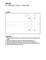
1. Attach left side shelf support and left side shelf wall to the left side shelf with five (5)
M5 x 10 screws from up to down as shown in Fig.9a.
Remove two (2) M6 x 13 Screws pre-assembled to towel bar ends, and use them to
attach towel bar to left side shelf wall. (NOTE: This step is Only used in 84244R.)
2. Hang shelf onto left front and left back legs as shown in Fig.9b.
3. Attach shelf to firebox as follows:
• Open lid, Attach left shelf to the left side panel from inside to outside of the firebox
with one (1) M6 x 13 (Stainless Steel)screw as shown in Fig.9b.
• Attach shelf to the left side panel from outside to inside of firebox with four (4) M5 x 10 screws
as shown in Fig.9c.
• Attach shelf from back to left side panel with two (2) M5 x 10 screws ;Connect left-side shelf
support and left-side shelf wall with one (1) M5 x 10 screw as shown in Fig.9c.
towel bar
Fig.9a
Fig.9b
Fig.9c
16

ASSEMBLY STEPS
STEP 10: Right-Side Shelf
1. Attach right side shelf support and right side shelf wall to the right side shelf with five(5)
M5 x 10 screws from up to down as shown in Fig.10a.
2. Hang shelf onto right front and right back legs as shown in Fig.10b.
3. Attach shelf to firebox as follows:
• Open lid, Attach right shelf to the right side panel from inside to outside of the firebox with
one (1) M6 x 13(S.S.) screw as shown in Fig.10b.
• Attach right shelf to the right side panel from outside to inside of firebox with four (4) M5 x 10
screws as shown in Fig.10c.
• Attach shelf from back to right side panel with two (2) M5 x 10 screws and connect right-side
shelf support and right-side shelf wall with one (1) M5 x 10 screw as shown in Fig.10c.
Fig.10c
Fig.10a
Fig.10b
17

ASSEMBL Y
ASSEMBLY STEPS
STEP 11: Side Burner
1. Unscrew and remove two front screws holding side burner in place as shown in Fig.11a.
2. Loosen side burner in side shelf and take it out from the top of side burner hole as shown in Fig.11b.
3. Pull the side burner valve with knob through the hole in right side panel as shown in Fig.11c,
and remove the packing material as shown in Fig.11d.
4. Remove knob from side burner valve. To remove pull knob straight out from valve stem
as shown in Fig.11d.
5. Unscrew the two screws at side of valve stem as shown in Fig.11e and Fig.11f.Take care
not to remove the other two screws, or the valve will come apart.
6. Insert valve stem through hole in fascia and attach with previously removed 2 screws
in previous step as shown in Fig.11g.
7. Replace side burner through the side burner hole as shown in Fig.11h, and place the side burner
tube over the valve, making sure that valve is inside side burner tube as shown in Fig.11i.
Fig.11a Fig.11b Fig.11c
Fig.11d Fig.11e Fig.11f
Fig.11g Fig.11h Fig.11i
18

ASSEMBLY STEPS
STEP 11: Side Burner
8.
Reattach side burner to side burner shelf with the 2 previously removed screws as shown in Fig.11j.
9. Push control knob onto side burner valve stem as shown in Fig.11k.
10. Insert the small tip of the side burner wire into the socket of side burner shown in Fig.11l
and Fig.11m. Secure by pressing on with white cap as shown in Fig.11n.
Also please note Fig.11l, Fig.11m and Fig.11n, these three views are of the underside of the right
side shelf, looking towards the front of the grill from the rear.
11. Place side burner grate on side burner as shown in Fig.11o.
12. The side burner is now fully assembled. This step (step 12) is only necessary if you find later that
you cannot light the side burner by using the side burner knob. Often, this is caused by poor
alignment of the igniter tip with a hole in the side burner. To adjust this alignment, grab the igniter tip
with a pair of needlenose pliers as shown in Fig. 11p. Using gentle force, move the position of the tip
so it is about 1/8" from the bottom of one of the holes in the burner, as shown in Fig. 11q.
Fig.11j Fig.11k Fig.11l
Fig.11m Fig.11n Fig.11o
Fig.11p Fig.11q
19

ASSEMBLY STEPS
STEP 12: Cooking Grates
1. Place heat diffusers over burners by inserting tabs into slots in front as shown in Fig.12b
and back of the firebox as shown in Fig.12c.
2. Place cooking grates onto grate rests as shown in Fig.12a.
3. Insert warming rack at the top of the firebox as shown as shown in Fig.12a.
Fig.12a
View from rear of the firebox
Fig.12b Fig.12c
Front of heat diffusers Rear of heat diffusers
20
/