Scotsman FM2400RH User manual
- Category
- Ice cube makers
- Type
- User manual
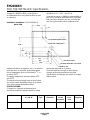
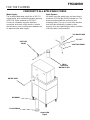
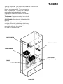
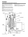
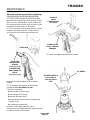
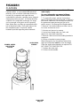
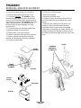
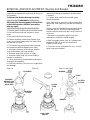
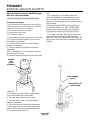
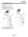
Scotsman FM2400RH is a freezer portion of a commercial ice machine, designed to be connected to the condensing section of a refrigeration system. It can be used with supermarket R-502 systems. The device consists of two evaporators, two gearmotors, two liquid line valves, two control boxes, two thermostatic expansion valves, and an EPR valve. It is suitable for indoor installations with controlled environment and specific temperature and water requirements. With a minimum circuit ampacity of 2.
Scotsman FM2400RH is a freezer portion of a commercial ice machine, designed to be connected to the condensing section of a refrigeration system. It can be used with supermarket R-502 systems. The device consists of two evaporators, two gearmotors, two liquid line valves, two control boxes, two thermostatic expansion valves, and an EPR valve. It is suitable for indoor installations with controlled environment and specific temperature and water requirements. With a minimum circuit ampacity of 2.


-
 1
1
-
 2
2
-
 3
3
-
 4
4
-
 5
5
-
 6
6
-
 7
7
-
 8
8
-
 9
9
-
 10
10
-
 11
11
-
 12
12
-
 13
13
-
 14
14
-
 15
15
-
 16
16
-
 17
17
-
 18
18
-
 19
19
-
 20
20
-
 21
21
-
 22
22
-
 23
23
-
 24
24
-
 25
25
-
 26
26
-
 27
27


Scotsman FM2400RH User manual
- Category
- Ice cube makers
- Type
- User manual
Scotsman FM2400RH is a freezer portion of a commercial ice machine, designed to be connected to the condensing section of a refrigeration system. It can be used with supermarket R-502 systems. The device consists of two evaporators, two gearmotors, two liquid line valves, two control boxes, two thermostatic expansion valves, and an EPR valve. It is suitable for indoor installations with controlled environment and specific temperature and water requirements. With a minimum circuit ampacity of 2.
Ask a question and I''ll find the answer in the document
Finding information in a document is now easier with AI
Related papers
-
Scotsman NM1852RH User manual
-
-
-
-
-
-
-
Scotsman FME800R User manual
-
-
Scotsman FME1200RL User manual