
PC, HDMI, DISPLAY PORT INTERFACE CONTROLLER
FOR TFT PANEL
Model: ALT-1920
Part number : 41764001X-3 or up
INSTRUCTIONS
CONTENTS
Page: 2. Introduction, How to Proceed, Usage Note, Disclaimer
3. System design – Diagram of a suggested system
4. Assembly notes – Important information about system elements
6. Connection & Operation – How to use the controller
10. Connectors, pinouts & jumpers – Essential connection information
20. Controller dimensions
21. Application notes
23. Troubleshooting
24. Specifications
25. Appendix I – Mode Support Table
27. Appendix II – RS-232 control protocols
31. Appendix III – DDC/CI support at ARGB, HDMI & Display port
32. Appendix IV – Mapping definition
34. Appendix V – Auto Color Gain
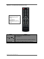
35. Appendix VI – DV remote control unit work for ALT-1920
36. Warranty, Caution & Limitation of Liability, Trademarks
37. Contact details
38. Revision History
It is essential that these instructions are read and understood before connecting or
powering up this controller.

Specifications subject to change without notice
© Digital View Ltd – Doc Ver 1.2: 4 Oct 2019 Page
2 of 38
Introduction
Designed for LCD monitor and other flat panel display applications, the ALT-1920 controller provides easy to use
interface controller for:
TFT (active matrix) LCDs with LVDS interface of 1920x1200, 1920x1080, 1920x480, 1680x1050, 1600x1200,
1400x1050, 1440x900, 1366x768, 1280x1024, 1280x800, 1280x768, 1024x768, 1024x600, 960x960, 800x600,
800x480, 640x480 resolution
Computer video signals of WUXGA, UXGA, SXGA, XGA, SVGA, VGA standard
Support HDMI, VGA, Display port input
Support LVDS interface panel
Support DDC/CI at ARGB, HDMI & Display port.
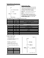
Ordering information :
Controller Part number Ordering part number
ALT-1920 P/N 41764001X-3 P/N 4176400XX-3
HOW TO PROCEED
Ensure you have all parts & that they are correct, refer to:
• Connection diagram (separate document for each panel)
• Connector reference (in following section)
• Assembly notes
Check controller switch & jumper settings (errors may damage the panel)
Prepare the PC
Connect the parts
Understand the operation and functions (in following section)
IMPORTANT USAGE NOTE
This product is for use by system developers and integrators, the manufacturer accepts no liability for damage or
injury caused by the use of this product. It is the responsibility of the developer, integrators or other user of this
product to:
Ensure that all necessary and appropriate safety measures are taken.
Obtain suitable regulatory approvals as may be required.
Check power settings to all component parts before connection.
Understand the operation and connectivity requirements of this controller.
DISCLAIMER
There is no implied or expressed warranty regarding this material.
Controller Solution Generator
Full web resource matching controllers & panels with connection diagrams for download.
See
at
:
http://www.digitalview.com/csg

Specifications subject to change without notice
© Digital View Ltd – Doc Ver 1.2: 4 Oct 2019 Page
3 of 38
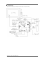
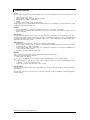
SYSTEM DESIGN
A typical LCD based display system utilising this controller is likely to comprise the following:

Specifications subject to change without notice
© Digital View Ltd – Doc Ver 1.2: 4 Oct 2019 Page
4 of 38
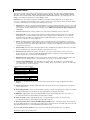
ASSEMBLY NOTES
This controller is designed for monitor and custom display projects using 1920 x 1200, 1920 x 1080, 1920x480, 1680x1050,
1600x1200, 1400x1050, 1440x900, 1366x768, 1280x1024, 1280x800, 1280x768, 1024x768, 1024x600, 800x600, 800x480,
640x480 resolution TFT panels with a VGA, SVGA, XGA, SXGA, UXGA, WUXGA signal input. The following provides some
guidelines for installation and preparation of a finished display solution.
Preparation: Before proceeding it is important to familiarize yourself with the parts making up the system and the various
connectors, mounting holes and general layout of the controller. As much as possible connectors have been labeled. Guides
to connectors and mounting holes are shown in the following relevant sections.
1. LCD Panel: This controller is designed for typical LVDS interface TFT panels with panel voltage 3.3V or 5V or 12V or 18V
LVDS interface. Due to the variation between manufacturers of signal timing and other panel characteristics factory setup
and confirmation should be obtained before connecting to a panel. (NOTE: Check panel power jumper settings before
connection)
2. Controller card: Handle the controller card with care as static charge may damage electronic components.
3. LVDS signal cable : In order to provide a clean signal it is recommended that LVDS signal cables are no longer than
46cm (18 inches). If loose wire cabling is utilized these can be made into a harness with cable ties. Care should be
taken when placing the cables to avoid signal interference. Additionally it may be necessary in some systems to add
ferrite cores to the cables to minimize signal noise.
4. Inverter: This will be required for the backlight of an LCD, some LCD panels have an inverter built in. As panels may
have 1 or more backlight tubes and the power requirements for different panel models backlights may vary it is important
to match the inverter in order to obtain optimum performance. See page 19 for the Application notes Inverter connection
section for more informations.
5. Inverter Cables: Different inverter models require different cables and different pin assignment. Make sure correct cable
pin out to match the inverter. Using wrong cable pin out may damage the inverter.
6. OSD switch mount controls: The following section discusses the controls required and the section on connectors
provides the detail. The controls are minimal: On/Off, Backlight Brightness (depends on inverter), OSD (5 momentary
buttons) analog VR type or (8 momentary buttons) digital type.
7. OSD switch mount controls cable: The cables to the function switches should be of suitable quality and length so that
impedance does not affect performance. Generally lengths up to 1 metre (3 feet) should be acceptable.
8. Controller status LED (Optional) : This LED indicates the controller status. The pin direction of the LED should be
corrected for right colour indication. Red colour stands for standby. Green colours stands for signal on. The status LED
is an optional part only, can be unconnected.
Controller LED status (LED1 & LED1A) :
State LED color
No signal & backlight off RED
With signal & backlight on GREEN
Update EDID in progress ORANGE
Power LED status (LED5A1) :
State LED status
Power input to controller ON
No power input to controller OFF
10. IR sensor: It is an optional part only, can be unconnected if not using IR remote control. See Appendix VI for button
definition.
11. RS-232 control interface : Firmware upgrade and serial control via this interface port. See Appendix II for the RS-232
serial control protocols.
12. Analog VGA Input Cable: As this may affect regulatory emission test results and the quality of the signal to the controller,
a suitably shielded cable should be utilized. This port support DDC/CI (See Appendix III in details).
13. HDMI input : Support HDMI 1.3 input up to 1080p/WUXGA resolution. Plug the HDMI cable to the connector P3 on
the controller board. This port support DDC/CI (See Appendix III in details).
14. Display Port Cable : Support single-link Display Port 1.2a. Plug the Display Port cable to the connector P4 on
the controller board. This port support DDC/CI (See Appendix III in details).
15. Audio Line out Jack (Stereo) output from HDMI / Display Port /CN13 : The J1 & CN14 port supports Stereo audio line
out from the HDMI / Display Port / CN13 audio source inputted. The J1 & CN14 port are the same audio path output. The audio
output will follow the input source selected (HDMI/Display port/VGA via CN13).
16. Line in audio (Stereo) from VGA : This port support Stereo audio line in from the VGA audio source inputted.

Specifications subject to change without notice
© Digital View Ltd – Doc Ver 1.2: 4 Oct 2019 Page
5 of 38
17. SPDIF Audio output : This port support SPDIF audio output from the HDMI / Display Port audio source inputted.
18. Backlight status input : It only functions when connecting with the panel which support backlight status detection pin.
19. Power Input: 12V / 24V DC is required, this should be a regulated supply. Although the controller provides power
regulation for the LCD power this does not relate to the power supplied to the backlight inverter. If an unregulated power supply
is provided to an inverter any fluctuations in power may affect operation, performance and lifetime of the inverter and or
backlight tubes. 24VDC input is required when the panel output voltage is 18VDC. Please refer to page 11-12 for proper
jumper settings.
•
••
• Power Safety: Note that although only 12VDC / 24VDC is supplied as ‘power-in’ a backlight inverter for panel
backlighting produces significantly higher voltages (the inverter does not connect to the ground plane). We strongly
advise appropriate insulation for all circuitry.
•
••
• EMI: Shielding will be required for passing certain regulatory emissions tests. Also the choice of external Controller to PC
signal cable can affect the result.
•
••
• Ground: The various PCB mounting holes are connected to the ground plane.
•
••
• Servicing: The board is not user serviceable or repairable. Warranty does not cover user error in connecting up to the
controller and is invalidated by unauthorized modification or repairs.
•
••
• Controller Mounting: It is recommended that a clearance of at least 10mm is provided above and 5mm below the
controller when mounted. Additionally consideration should be given to:
• Electrical insulation.
• Grounding.
• EMI shielding.
• Cable management. Note: It is important to keep panel signal cables apart from the inverter & backlight cables to
prevent signal interference.
• Heat & Ventilation: Heat generated from other sources, for example the backlight of a very high brightness panel
may generate significant heat which could adversely affect the controller.
• Other issues that may affect safety or performance.
•
••
• PC Graphics Output: A few guidelines:
• Signal quality is very important, if there is noise or instability in the PC graphics output this may result in visible noise
on the display.
• Refer to graphics modes table in specifications section for supported modes.
• Non-interlaced & interlaced video input is acceptable.
IMPORTANT: Please read the Application Notes section for more information.

Specifications subject to change without notice
© Digital View Ltd – Doc Ver 1.2: 4 Oct 2019 Page
6 of 38
CONNECTION & OPERATION
CAUTION: Never connect or disconnect parts of the display system when the system is powered up as this may cause serious
damage.
CONNECTION
Connection and usage is quite straight forward (it is useful to have the relevant connection diagram available at this time):
1. LCD panel & Inverter: Connect the inverter (if it is not built-in the panel) to the CCFT lead connector of the LCD
panel.
2. LVDS type panels: Plug the LVDS signal cable direct to J3 (if necessary). Insert the panel end of the cable to the
LCD panel connector.
3. Inverter & Controller: Plug the inverter cable to CNB1 and CNA1 (if necessary). Plug another end to the connector
on the inverter.
4. Function switch & Controller: Plug the OSD switch mount cable to CNC1 on the controller board and another to
the OSD switch mount.
5. LED 1 : Plug in a 3-way with dual colour LED to connector LED1 on the controller board for indicating the controller
status.
6. LED 2 : Plug in a 3-way with dual color LED to connector LED2 on the controller board for indicating the backlight
status. This function is only available when CNB2 are proper connected and the panel is support the backlight status
function.
7. IR & Controller: Plug in a 3-way with IR sensor to connector IR1 on the controller board.
8. Jumpers : Check all jumpers are set correctly. Details referring the connection diagram at
http://www.digitalview.com/controllers/csg.php
9. Jumpers & Inverter & Panel voltage: Particularly pay attention to the settings of JA3, JA6, JB2, JB3. JB2 & JB3
are used for inverter control (read inverter specification and information on the jumper table to define the correct
settings). JA3 & JA6 are used for panel voltage input (read panel specification and information on the jumper table
to define the correct settings).
10. HDMI cable : Plug the HDMI cable to the connector P3 on the controller board.
11. VGA cable : Plug the VGA cable to the connector P1 on the controller board.
12. Display port cable : Plug the Display port cable to connector P4 on the controller board.
13. Power supply & Controller: Plug the DC 12V / 24V power in to the connector PP2. You can consider to use
DigitalView mating power cable P/N 426013800-3, 160mm. Please read the jumper table in page 11-12 to define the
correct settings. Otherwise it may break down the panel.
14. Power on: Switch on the controller board and panel by using the OSD switch mount.
CAUTION: Never connect or disconnect parts of the display system when the system is powered up as this may cause serious
damage.
Controller LED status (LED1 & LED1A) :
State LED color
No signal & backlight off RED
With signal & backlight on GREEN
Update EDID in progress ORANGE
Power LED status (LED5A1) :
State LED status
Power input to controller ON
No power input to controller OFF
General:
• If you are using supplied cables & accessories, ensure they are correct for the model of panel and controller.
• If you are making your own cables & connectors refer carefully to both the panel & inverter specifications and the section
in this manual, “Connectors, Pinouts & Jumpers” to ensure the correct pin to pin wiring.
PC SETTINGS
The controller has been designed to take a very wide range of input signals however to optimize the PC’s graphics
performance we recommend choosing 60Hz vertical refresh rate – this will not cause screen flicker.
OPERATION
Once the system has been connected and switched on there are a number of functions available to adjust the display
image as summarized in the following sections. The settings chosen will be saved for each mode independently.

Specifications subject to change without notice
© Digital View Ltd – Doc Ver 1.2: 4 Oct 2019 Page
7 of 38
LCD DISPLAY SYSTEM SETTINGS
NOTE: By way of explanation the following refers to a set of sample buttons that may be obtained as an option. In
addition to power on/off and connection for backlight brightness the controller provides an On Screen Display of certain
functions which are controlled by 5 momentary type buttons (analog VR type) or 8 momentary type buttons (digital type):
Controls Analog VR type Digital type
On/Off – turns controller board power on VR toggle switch On/Off button
Brightness – controls backlight brightness Rotary VR Brightness +/- buttons
Menu – turns OSD menu On or Off (it will auto time
off) (Function with signal input only)
Menu button Menu button
Menu- Power on/off* Power ON - Press Menu
button
Power OFF - Hold Menu
button for 3-4 sec
Power ON - Press Menu
button
Power OFF - Hold Menu button
for 3-4 sec
Select – Select function / Confirm
(under OSD menu on state)
SEL DN SEL DN
Move up to select individual RGB color level OSD
page
(under OSD menu on state)
SEL UP SEL UP
+ – increase the setting / moves the selector to the
next function
(under OSD menu on state)
+ +
- - decrease the setting / moves the selector to the
previous function
(under OSD menu on state)
- -
Reset to Factory Defaults Press and hold SEL DN
button, then power on the
controller
Press and hold SEL DN button,
then power on the controller
Input source selection hotkey (under OSD menu off
state)
+ +
Volume adjustment (under OSD menu off
state)
SEL UP / SEL DN SEL UP / SEL DN
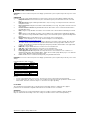
Remark : * The jumper JP6 must be always closed when using the 'Default power' feature.
ON/Off/Brightness
SEL UP
SEL DN
+
-
Menu
Analog VR type
Digital type
12V / 24VDC power input :
Analog 10K VR Type OSD
switch mount uses
P/N 410680550-3 or up
12V / 24VDC power input :
Digital 10K Type OSD switch
mount uses
P/N 416100520-3 or up
12VDC power input :
Digital 10K Type OSD switch
mount uses
P/N 416100510-3

Specifications subject to change without notice
© Digital View Ltd – Doc Ver 1.2: 4 Oct 2019 Page
8 of 38
OSD Functions
Input Source
VGA Select the input video signal to VGA
HDMI Select the input video signal to HDMI
DisplayPort Select the input video signal to DisplayPort
Auto Source
Seek
Off : Disable the Auto source seek function
On : Enable the Auto source seek function [Default]
Default Power Off : When the controller detects power in, it will stay in 'Stand-by' mode.
On : When the controller detects power in, it will turn on the power and display image.
[Default]
Color
Settings
Gamma 1.8 / 2.0 / 2.2 / 2.4 / 2.6 [Default 2.2]
Color Temp. 9300K
7500K [Default]
6500K
5000K
4200K
User Color
Red : Press – or + (- + ) 0~100 [Default : 100]
Green : Press – or + (- + ) 0~100 [Default : 100]
Blue : Press – or + (- + ) 0~100 [Default : 100]
Picture
Quality
Black Level
Increase/decrease brightness level.
Press – or + (- +) 0~100 [Default : 50]
Contrast
Increase/decrease contrast level.
Press – or + (- + ) 0~100 [Default : 50]
Sharpness
Increase/decrease sharpness level.
Press – or + (- + ) 0~100 [Default : 50]
Brightness
Backlight brightness adjustment
Press – or + (- + ) 0~100
Invert Off / On : Invert for the backlight brightness
Control
D/A / PWM : Selection for voltage level dimming control / PWM dimming control
Frequency(Hz) Backlight frequency 100 ~ 440Hz in a step of 20
Display Settings
Aspect Ratio Full : Scaling format to Fill Screen.[Default]
4:3 : Scaling format to 4:3
H.Position Use +/- to adjust image position horizontally.
Press
–
or + (
-
+
)
0~100
V.Position Use +/- to adjust image position vertically.
Press
–
or + (
-
+
)
0~100
Clock Adjust the image horizontal size.
Press
–
or + (
-
+
)
0~
100
Phase Fine tune the data sampling position (adjust image quality)
Press
–
or + (
-
+
)
0~100
Auto Adjust Auto adjust the positions, phase, frequency
Auto Color Auto color calibration [See Appendix IV]
Audio Setting Sound (Function when HDMI and Display Port connected and selected)
Volume Increase/decrease volume level, total: 100 steps
Press – or + (- + ) 0~100 [Default : 50]
Mute Off / On [Default: OFF]
Other
Settings

Specifications subject to change without notice
© Digital View Ltd – Doc Ver 1.2: 4 Oct 2019 Page
9 of 38
Language OSD menu language selection :
English
French
German
Spanish
OSD Orientation OSD menu rotation in degree
0 [Default]
90
180
270
OSD Transparency Transparency : Set OSD transparency
Press – or + (- + ) 0~100 [Default : 0]
OSD H.Position Use +/- to adjust OSD menu position horizontally.
Press – or + (- + ) 0~100 [Default : 50]
OSD V.Position Use +/- to adjust OSD menu position vertically.
Press – or + (- + ) 0~100 [Default : 50]
OSD Timeout Timer : OSD Timeout in seconds
Press – or + (- + ) 0~60 (ON for Always ON).
[Default : 10]
Factory Reset Reset : Load factory default settings.
Press down on OSD keypad to factory reset
Information
Input signal information reported : Resolution / H.Freq / V.Freq
[Firmware version : V1.00.00 or up]
Items marked 4 have sub menus.
Exit the OSD menu to save the setting chosen

Specifications subject to change without notice
© Digital View Ltd – Doc Ver 1.2: 4 Oct 2019 Page
10 of 38
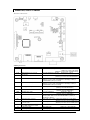
CONNECTORS, PINOUTS & JUMPERS
The various connectors are:
Summary: Connectors
Ref Purpose Description
CN8 Serial control Molex 53261-0671, 6 ways 1.25mm pitch
(Mating type : Molex 51021-0600)
(Matching connection cable P/N 426171800-3)
CN9 Ambient light sensor connector
(Reserved)
JST 3-way, B3B-PH-K compatible (Matching type : PHR-3)
CN11 SPDIF Audio Output JST 2-way, S2B-ZR-SM4A (Mating type : ZHR-2)
(Matching connection cable P/N 426007400-3)
CN13 Audio line in (Stereo) JST B4B-PH-K-S compatible (Matching type : PHR-4)
Matching connection cable P/N 426002500-3 (RCA plug, 610mm) or
P/N 426002600-3 (RCA jack, 150mm)
CN14 Audio line out (Stereo) JST B4B-PH-K-S compatible (Matching type : PHR-4)
Matching connection cable P/N 426002500-3 (RCA plug, 610mm) or
P/N 426002600-3 (RCA jack, 150mm)
CNA1 Auxiliary power output JST 4-way, S4B-XH-A (Mating type : XHP-4)
(Matching cable P/N 426040200-3)
CNB1 Backlight inverter JST 5-way, S5B-XH-A (Mating type : XHP-5)
(Matching cable P/N 426058300-3)
CNB2 Backlight status input JST 2-way, S2B-XH-A (Mating type : XHP-2)
(Matching cable P/N 426020800-3)
CNC1 OSD controls Hirose DF13A-12P-1.25H (Mating type : DF13-12S-1.25C)
(Matching OSD switch mount cable P/N 426122200-3 (150mm) or
426122210-3 (250mm)
IR1 Infra-Red sensor connector Molex 53261-0371, 3 way 1.25mm pitch (Mating type : 51021-0300)
(Matching connection cable P/N 426031500-3)
LED1 Dual color LED connector for
controller status
JST 3-way, S3B-ZR-SM4A (Mating type : ZHR-3)
(Matching connection cable P/N 426031400-3)
J1 Audio line out jack (Stereo) output
from HDMI / Display Port / CN13
3.5mm PHONE JACK
J3 LVDS panel signal JAE FI-RE51S-HF (Mating type : JAE FI-RE51HL)
P1 ARGB signal input DB-15 way high density 3 row

Specifications subject to change without notice
© Digital View Ltd – Doc Ver 1.2: 4 Oct 2019 Page
11 of 38
P3 HDMI signal input HDMI connector (Type A)
P4 Display Port input Display port connector
PP2 Power input Molex 43650-0200 compatible (Mating type : Molex 43645-0200
compatible)
(Matching power cable : P/N 426013800-3, 160mm)
Summary: Jumpers setting
Ref Purpose Note
JA1 On board +5V logic power enable 1-3 & 2-4 closed, factory set, do not remove
JA3 Panel power voltage select See panel voltage setting table 1
CAUTION: Incorrect setting will cause panel damage
JA6 Panel power voltage select See panel voltage setting table 1
CAUTION: Incorrect setting will cause panel damage
JB1 Backlight brightness voltage range 1-2 closed = 3.3V max
2-3 closed = 5V max
JB2 Backlight inverter on/off control – signal level 1-2 = On/Off control signal ‘High’ = +3.3V
2-3 = On/Off control signal ‘High’ = +5V
Open = On/Off control signal ‘High’ = Open collector
CAUTION: Incorrect setting can damage inverter.
JB3 Backlight inverter on/off control – polarity 1-2 = control signal ‘high’ = CCFT ON
2-3 = control signal ‘low’ = CCFT ON
JB5 Backlight control type selection 1-2 = VR/Digital switch mount control
3-4 = Analog backlight brightness control via RS-232
command (0xe0) – voltage range 0~5V
5-6 = PWM (Pulse Width Modulation) brightness
JB6 Backlight status 1-2, 3-4 closed = Backlight status Low – Normal
1-3, 2-4 closed = Backlight status High - Normal
Open = Backlight status not used
JB7 Backlight control voltage on CNB1 pin 4
(Function when JB5 sets 1-2 closed)
Open = For OSD switch mount control (Default)
1-2 = 0V
2-3 = 3.3V / 5V controlled by JB1
JP1 Reserved Reserved for internal programming use
JP2 Custom configuration Enable J3 - pin 16 (OP1) 3.3V enable controlled by JP2
JP3 Custom configuration Enable J3 - pin 17 (OP2) 3.3V enable controlled by JP3
JP4 Custom configuration Enable J3 - pin 18 (OP3) 3.3V enable controlled by JP4
JP5 Custom configuration Enable J3 - pin 19 (OP4) 3.3V enable controlled by JP5
JP6 Input power control Short = External switch control
Open = Switch mount control
SW1 Panel selection See table below
SW2 Panel selection See table below

Specifications subject to change without notice
© Digital View Ltd – Doc Ver 1.2: 4 Oct 2019 Page
12 of 38
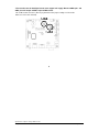
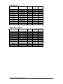
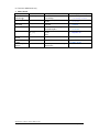
Table 1 : Panel voltage setting table :
Input voltage via
PP2 Panel Voltage JA3 JA6 Jumper on board
12VDC
3.3V 3V3 closed
1-3 & 2-4
5V 5V closed 1-3 & 2-4
12V OPEN 5-7 & 6-8
CAUTION: Incorrect setting can damage panel & controller

Specifications subject to change without notice
© Digital View Ltd – Doc Ver 1.2: 4 Oct 2019 Page
13 of 38
Input voltage via
PP2 Panel Voltage JA3 JA6 Jumper on board
24VDC**
3.3V 3V3 closed
1-3 & 2-4
5V 5V closed 1-3 & 2-4
12V 12V closed
3-5 & 4-6
18V 18V closed
3-5 & 4-6

Specifications subject to change without notice
© Digital View Ltd – Doc Ver 1.2: 4 Oct 2019 Page
14 of 38
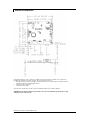
* Please make sure the backlight inverter must support 24V supply. Because CNA1 pin 1 and
CNB1 pin 2 will output 24VDC if input 24VDC via PP2.
!
JA3 & JA6 location on board : (Please pay attention to the jumper settings on JA3 & JA6
which are red in color on board)
JA6
!
! JA3

Specifications subject to change without notice
© Digital View Ltd – Doc Ver 1.2: 4 Oct 2019 Page
15 of 38
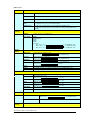
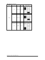
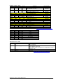
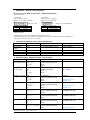
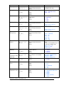
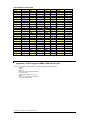
DIP Switch selection – SW1
Pos #1 Pos #2 Pos #3 Pos.#4 Description Panel resolution
For WUXGA panel
OFF OFF OFF OFF Samsung LTM230HT10 (Tested) 1920x1080
AUO T215HVN01.0 (Tested) 1920x1080
ON OFF OFF OFF Samsung LTM220CS01 (Tested) 1920x1200
OFF OFF ON OFF AUO G173HW01 (Tested) 1920x1080
KOE TX18D200VM0EAA (Tested) 1920x1080
For UXGA panel
ON OFF OFF OFF NEC NL160120BC27-32B 1600x1200
For WXGA panel
ON OFF OFF OFF AUO G156XW01.V10 1366x768
OFF ON ON OFF AUO B101EW05 V0 1280x800
For SXGA panels
ON OFF OFF ON HannStar HSD170ME13-A06 1280x1024
For XGA panel
OFF OFF ON ON AUO M150XN07 V2 (Tested) 1024x768
SVGA
OFF OFF ON OFF NEC NL8060BC26-35F 800x600
VGA/WVGA
OFF ON OFF OFF Mitsubishi AA104VJ02 640x480
OFF ON OFF ON NEC NL8048BC19-02 800x480
Others
OFF OFF ON ON HannStar HSD190MGW1-A00 1440x900
For additional and recent added panels, see ALT-1920 panel support table at http://www.digitalview.com/controllers/csg.php
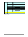
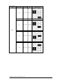
Pos #5 Pos #6 Pos #7 Description
OFF OFF OFF WUXGA
ON OFF OFF UXGA
OFF ON OFF SXGA
ON ON OFF WXGA
OFF OFF ON XGA
ON OFF ON SVGA
OFF ON ON VGA / WVGA
ON ON ON Others
SW1 Pos 8 = Reserved.
DIP switch selection – SW2
Pos. # Function Description
1 Panel pixel format OFF : Double Pixel
ON : Single Pixel
2 LVDS data mapping select
ON : Mapping A (LVDS panel)
OFF : Mapping B (LVDS panel)
Please adjust to get the correct picture. See as Appendix IV for details of
mapping A and B.
3 Reserved Reserved
4 Reserved Reserved
The most current list can be found the controller solution generator at http://www.digitalview.com/controllers/csg.php

Specifications subject to change without notice
© Digital View Ltd – Doc Ver 1.2: 4 Oct 2019 Page
16 of 38
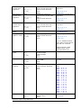
CN8 – RS-232 serial control: Molex 53261-0671, 6 ways 1.25mm pitch (Matching type : Molex 51021-0600)
PIN SYMBOL DESCRIPTION
1 SDATA Reserved
2 SCLK Reserved
3 VCC +5V
4 TXD RS-232 Tx data
5 GND Ground
6 RXD RS-232 Rx data
CN9 – Ambient light sensor connector : JST B3B-PH-K (Matching type : PHR-3)
PIN SYMBOL DESCRIPTION
1 GND Ground
2 VCC_5V VCC 5V
3 ALSF Ambient light sensing feedback
CN11 – SPDIF Audio Output JST 2-way, S2B-ZR-SM4A (Mating type : JST ZHR-2)
PIN SYMBOL DESCRIPTION
1 SPDIF_OUT SPDIF audio out
2 GND Ground
CN13 –Audio line in (Stereo) connector: JST B4B-PH-K compatible (Matching type : PHR-4)
PIN SYMBOL DESCRIPTION
1 GND GND
2 AUDIO LIN AUDIO LINE IN LEFT
3 GND GND
4 AUDIO RIN AUDIO LINE IN RIGHT
CN14 –Audio line out (Stereo) connector: JST B4B-PH-K compatible (Matching type : PHR-4)
PIN SYMBOL DESCRIPTION
1 GND GND
2 AUDIO LOUT AUDIO LINE OUT LEFT
3 GND GND
4 AUDIO ROUT AUDIO LINE OUT LEFT
CNA1 - Auxiliary power output: JST S4B-XH-A (Matching type : XHP-4)
PIN SYMBOL DESCRIPTION
1 AUX POWER +12V DC, 500mA max / +24V DC, 3A max
2 GND Ground
3 GND Ground
4 AUX 5V +5V DC, 500mA max
CNB1 – Backlight inverter connector: JST S5B-XH-A (Matching type : XHP-5)
PIN SYMBOL DESCRIPTION
1 GND Ground
2 VBKL Backlight power supply, +12VDC / +24V DC, 3A max
3 BLCTRL Backlight On/Off control signal (refer to JB2 & JB3)
4 BVR_WIP Backlight brightness VR pin WIP
5 BVR_A Backlight brightness VR pin A
CNB2 – Backlight status connector : JST B2B-XH-A (Matching type : XHP-2)
PIN SYMBOL DESCRIPTION
1 BL_S Backlight status signal
2 GND Ground
CNC1 – OSD switch mount control, Hirose DF13A-12P-1.25H (Mating type : DF13-12S-1.25C)
PIN SYMBOL DESCRIPTION
1 PSWIN Power button A
2 SW_ON Power button B
3 BVR_A Backlight Brightness VR pin A
4 BVR_WIP Backlight Brightness R pin WIP
5 BVR_B Backlight Brightness VR pin B (470 ohm resistor to +5V Vcc)
6 GND Ground
7 MENU OSD menu
8 -/LEFT OSD -/Left
9 +/RIGHT OSD +/Right
10 SEL_DN OSD Select down
11 SEL_UP OSD Select up
12 POWER KEY OSD POWER KEY

Specifications subject to change without notice
© Digital View Ltd – Doc Ver 1.2: 4 Oct 2019 Page
17 of 38
IR1 – Infra-Red sensor connector: Molex 53261-0371, 3 way 1.25mm pitch (Matching type : Molex 51021-0300)
PIN SYMBOL DESCRIPTION
1 GND Ground
2 STDBY_Vcc Stand by voltage
3 IR Data IR data
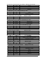
J3 – LVDS output connector: JAE FI-RE51S-HF (Matching type : JAE FI-RE51HL)
PIN SYMBOL DESCRIPTION
1 VDD (+12V/18V) Panel power supply (+12V / 18V) (selected by JA3 & JA6)
2 VDD (+12V/18V) Panel power supply (+12V / 18V) (selected by JA3 & JA6)
3 VDD (+12V/18V) Panel power supply (+12V / 18V) (selected by JA3 & JA6)
4 VDD (+12V/18V) Panel power supply (+12V / 18V) (selected by JA3 & JA6)
5 VDD (+12V/18V) Panel power supply (+12V / 18V) (selected by JA3 & JA6)
6 VDD (3,3V/5V) Panel power supply (3,3V/5V) (selected by JA3 & JA6)
7 VDD (3,3V/5V) Panel power supply (3,3V/5V) (selected by JA3 & JA6)
8 VDD (3,3V/5V) Panel power supply (3,3V/5V) (selected by JA3 & JA6)
9 VDD (3,3V/5V) Panel power supply (3,3V/5V) (selected by JA3 & JA6)
10 VDD (3,3V/5V) Panel power supply (3,3V/5V) (selected by JA3 & JA6)
11 GND Ground
12 GND Ground
13 GND Ground
14 GND Ground
15 GND Ground
16 OP1 3.3V enable controlled by JP2
17 OP2 3.3V enable controlled by JP3
18 OP3 3.3V enable controlled by JP4
19 OP4 3.3V enable controlled by JP5
20 GND Ground
21 GND Ground
22 NC No connection
23 NC No connection
24 TXA3+ Positive differential LVDS data bit A3
25 TXA3- Negative differential LVDS data bit A3
26 GND Ground
27 TXAC+ Positive LVDS clock for A channel
28 TXAC- Negative LVDS clock for A channel
29 GND Ground
30 TXA2+ Positive differential LVDS data bit A2
31 TXA2- Negative differential LVDS data bit A2
32 TXA1+ Positive differential LVDS data bit A1
33 TXA1- Negative differential LVDS data bit A1
34 TXA0+ Positive differential LVDS data bit A0
35 TXA0- Negative differential LVDS data bit A0
36 GND Ground
37 NC No connection
38 NC No connection
39 TXB3+ Positive differential LVDS data bit B3
40 TXB3- Negative differential LVDS data bit B3
41 GND Ground
42 TXBC+ Positive LVDS clock for B channel
43 TXBC- Negative LVDS clock for B channel
44 GND Ground
45 TXB2+ Positive differential LVDS data bit B2
46 TXB2- Negative differential LVDS data bit B2
47 TXB1+ Positive differential LVDS data bit B1
48 TXB1- Negative differential LVDS data bit B1
49 TXB0+ Positive differential LVDS data bit B0
50 TXB0- Negative differential LVDS data bit B0
51 GND Ground

Specifications subject to change without notice
© Digital View Ltd – Doc Ver 1.2: 4 Oct 2019 Page
18 of 38
LED1 – Dual color LED connector for controller status, JST 3-way, S3B-ZR-SM4A (Mating type : JST ZHR-3)
PIN DESCRIPTION
1 Green LED pin (anode)
2 LED pin common (cathode)
3 Red LED pin (anode)
P1 - Analog VGA input – DB-15 way high density 3 row
PIN SYMBOL DESCRIPTION
1 PCR Red, analog
2 PCG Green, analog
3 PCB Blue analog
4 ID2 Reserved for monitor ID bit 2 (grounded)
5 DGND Digital ground
6 AGND Analog ground red
7 AGND Analog ground green
8 AGND Analog ground blue
9 DDC_5V +5V power supply for DDC (optional)
10 DGND Digital ground
11 ID0 Reserved for monitor ID bit 0 (grounded)
12 DDC_SDA DDC serial data
13 HS_IN Horizontal sync or composite sync, input
14 VS_IN Vertical sync, input
15 DDC_SCL DDC serial clock
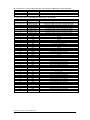
P3 – HDMI connector
PIN SYMBOL DESCRIPTION
1 DATA2+ TMDS Data2+
2 DATA2S TMDS Data2 Shield
3 DATA2- TMDS Data2–
4 DATA1+ TMDS Data1+
5 DATA1S TMDS Data1 Shield
6 DATA1- TMDS Data1–
7 DATA0+ TMDS Data0+
8 DATA0S TMDS Data0 Shield
9 DATA0- TMDS Data0–
10 CLK+ TMDS Clock+
11 CLK@ TMDS Clock Shield
12 CLK- TMDS Clock–
13 CEC CEC
14 NC No connection
15 SCL SCL (I²C Serial Clock for DDC)
16 SDA SDA (I²C Serial Data Line for DDC)
17 CEC/GND Ground
18 +5V +5 V Power (max 50 mA)
19 HPDET Hot Plug Detect
P4 – Display Port input
PIN SYMBOL DESCRIPTION
1 ML_Lane 0 (p) Lane 0 (positive)
2 GND Ground
3 ML_Lane 0 (n) Lane 0 (negative)
4 ML_Lane 1 (p) Lane 1 (positive)
5 GND Ground
6 ML_Lane 1 (n) Lane 1 (negative)
7 ML_Lane 2 (p) Lane 2 (positive)
8 GND Ground
9 ML_Lane 2 (n) Lane 2 (negative)
10 ML_Lane 3 (p) Lane 3 (positive)
11 GND Ground
12 ML_Lane 3 (n) Lane 3 (negative)
13 CONFIG1 connected to Ground
1)
14 CONFIG2 connected to Ground
1)
15 AUX CH (p) Auxiliary Channel (positive)
16 GND Ground
17 AUX CH (n) Auxiliary Channel (negative)
18 Hot Plug Hot Plug Detect
19 GND Ground
20 DP_PWR Power for connector (3.3 V 500 mA)

Specifications subject to change without notice
© Digital View Ltd – Doc Ver 1.2: 4 Oct 2019 Page
19 of 38
PP2 - Power supply (Mating type : Molex 43645-0200 compatible)
PIN DESCRIPTION
1 +12VDC 5A max / +24VDC 5A max
2 Ground

Specifications subject to change without notice
© Digital View Ltd – Doc Ver 1.2: 4 Oct 2019 Page
20 of 38
CONTROLLER DIMENSIONS
The maximum thickness of the controller is 17.45mm (measured from bottom of PCB to top of components,
including any underside components & leads). We recommend clearances of:
• 5mm from bottom of PCB - if mounting on a metal plate we also recommend a layer of suitable insulation
material is added to the mounting plate surface.
• 10mm above the components
• 3~5mm around the edges
Any of the holes shown above can be used for mounting the PCB, they are 3.2mm in diameter.
CAUTION: Ensure adequate insulation is provided for all areas of the PCB with special attention to high
voltage parts such as the inverter.
Page is loading ...
Page is loading ...
Page is loading ...
Page is loading ...
Page is loading ...
Page is loading ...
Page is loading ...
Page is loading ...
Page is loading ...
Page is loading ...
Page is loading ...
Page is loading ...
Page is loading ...
Page is loading ...
Page is loading ...
Page is loading ...
Page is loading ...
Page is loading ...
-
 1
1
-
 2
2
-
 3
3
-
 4
4
-
 5
5
-
 6
6
-
 7
7
-
 8
8
-
 9
9
-
 10
10
-
 11
11
-
 12
12
-
 13
13
-
 14
14
-
 15
15
-
 16
16
-
 17
17
-
 18
18
-
 19
19
-
 20
20
-
 21
21
-
 22
22
-
 23
23
-
 24
24
-
 25
25
-
 26
26
-
 27
27
-
 28
28
-
 29
29
-
 30
30
-
 31
31
-
 32
32
-
 33
33
-
 34
34
-
 35
35
-
 36
36
-
 37
37
-
 38
38


Ask a question and I''ll find the answer in the document
Finding information in a document is now easier with AI
Related papers
-
Digital View HLT-1920 Owner's manual
-
-
-
-
-
-
-
-
DVS -30RF-2 Owner's manual
-
