H&S TS5134 Operating instructions
- Category
- Spreader
- Type
- Operating instructions

Manufactured By
H&S MANUFACTURING CO.,INC.
P.O. BOX 768 (715) 387-3414 FAX (715) 384-5463
MARSHFIELD, WISCONSIN 54449
HSMFG1212 Part #59624
Revision #1
5134 Starting Serial #303082
5134 TOP SHOT
MANURE SPREADER
OPERATOR’S MANUAL
WARNING
READ AND UNDERSTAND THIS MANUAL
BEFORE OPERATING THIS EQUIPMENT.
UNSAFE OPERATION OR MAINTENANCE OF
THIS EQUIPMENT CAN RESULT IN SERIOUS
INJURY OR DEATH.

CONTENTS
Warranty & Warranty Registration Card . . . . . . . . . . . . . . . . . . . . . . . . . . . . . . . . . . . . . . . . . . . . . . . 1-2
Manufacturer’s Statement . . . . . . . . . . . . . . . . . . . . . . . . . . . . . . . . . . . . . . . . . . . . . . . . . . . . . . . . . . . . .2
Dealer Pre-Delivery Checklist . . . . . . . . . . . . . . . . . . . . . . . . . . . . . . . . . . . . . . . . . . . . . . . . . . . . . . . . . 3
Dealer Delivery Checklist . . . . . . . . . . . . . . . . . . . . . . . . . . . . . . . . . . . . . . . . . . . . . . . . . . . . . . . . . . . . . 5
Safety Information - Be Alert Symbol . . . . . . . . . . . . . . . . . . . . . . . . . . . . . . . . . . . . . . . . . . . . . . . . . . . . 7
Safety Information - Explanation of Safety Signs . . . . . . . . . . . . . . . . . . . . . . . . . . . . . . . . . . . . . . . . . . 8
Safety Decals . . . . . . . . . . . . . . . . . . . . . . . . . . . . . . . . . . . . . . . . . . . . . . . . . . . . . . . . . . . . . . . . . . . . 9-10
Safety Information - Warning - Owner Must Read and Understand . . . . . . . . . . . . . . . . . . . . . . . . . . . 11
Cap Screw Torque Values . . . . . . . . . . . . . . . . . . . . . . . . . . . . . . . . . . . . . . . . . . . . . . . . . . . . . . . . . . . . 12
Set-Up & Assembly . . . . . . . . . . . . . . . . . . . . . . . . . . . . . . . . . . . . . . . . . . . . . . . . . . . . . . . . . . . . . . . . 13
Transporting . . . . . . . . . . . . . . . . . . . . . . . . . . . . . . . . . . . . . . . . . . . . . . . . . . . . . . . . . . . . . . . . . . . . . . . . 14
Storage . . . . . . . . . . . . . . . . . . . . . . . . . . . . . . . . . . . . . . . . . . . . . . . . . . . . . . . . . . . . . . . . . . . . . . . . . . 14
Preparing for Operation . . . . . . . . . . . . . . . . . . . . . . . . . . . . . . . . . . . . . . . . . . . . . . . . . . . . . . . . . 15-16
Operation . . . . . . . . . . . . . . . . . . . . . . . . . . . . . . . . . . . . . . . . . . . . . . . . . . . . . . . . . . . . . . . . . . . . . . 17-22
Adjustments . . . . . . . . . . . . . . . . . . . . . . . . . . . . . . . . . . . . . . . . . . . . . . . . . . . . . . . . . . . . . . . . . . . 23-24
Service . . . . . . . . . . . . . . . . . . . . . . . . . . . . . . . . . . . . . . . . . . . . . . . . . . . . . . . . . . . . . . . . . . . . . . . . 25-26
Optional Equipment . . . . . . . . . . . . . . . . . . . . . . . . . . . . . . . . . . . . . . . . . . . . . . . . . . . . . . . . . . . . . . . . . . 27
Lubrication Guide . . . . . . . . . . . . . . . . . . . . . . . . . . . . . . . . . . . . . . . . . . . . . . . . . . . . . . . . . . . . . . . . 28-31
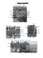
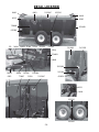
Decal Location . . . . . . . . . . . . . . . . . . . . . . . . . . . . . . . . . . . . . . . . . . . . . . . . . . . . . . . . . . . . . . . . . . 32-34
Troubleshooting Guide . . . . . . . . . . . . . . . . . . . . . . . . . . . . . . . . . . . . . . . . . . . . . . . . . . . . . . . . . . . . . 35
Service Notes . . . . . . . . . . . . . . . . . . . . . . . . . . . . . . . . . . . . . . . . . . . . . . . . . . . . . . . . . . . . . . . . . . . . . . . 36
Specifications . . . . . . . . . . . . . . . . . . . . . . . . . . . . . . . . . . . . . . . . . . . . . . . . . . . . . . . . . . . . Inside Back Cover

WARRANTY
FILL OUT AND MAIL
IMMEDIATEY TO MAKE
WARRANTY EFFECTIVE
10/12
H&S WARRANTY
H&S Manufacturing Co., Inc. (“H&S”) warrants this product to be free from defect in material and workmanship.
Except as noted below, this warranty term is twelve (12) months from the date of delivery of the product to the original
purchaser by an authorized H&S dealer. Under this warranty , H&S will repair or replace, at its option, any covered part
which is found to be defective in material or workmanship during the applicable warranty term. In no case will the
covered repair cost of a part or parts exceed the replacement cost of that part. Warranty service must be performed by
H&S or a dealer authorized by H&S to sell and/or service the product involved, which will use only new or remanufactured
parts or components furnished by H&S. This warranty includes approved parts and labor to fix the product but does not
include, and the purchaser is responsible for, any service call and/or transportation of the product to and from the
dealer’s place of business, for any premium charged for overtime labor requested by the purchaser, and for any
service work not directly related to any defect covered under this warranty. This warranty includes only those compo-
nents of the product manufactured by H&S. Warranty for any component not manufactured by H&S including, but not
limited to, engines, batteries, tires, rims, hydraulic motors, pumps, etc. are covered by the warranty, if any, provided
separately by their respective manufacturers.
This warranty in all its parts, is extended solely to the original purchaser of the product, is terminated upon any
subsequent transfer or sale from or by the original purchaser and extends no third party benefits or rights whatsoever.
The warranty term for any product used in any commercial, custom, for hire or rental application, is limited to six (6)
months from the date of delivery of the product to the original purchaser or the first day of service, whichever comes
first, by an authorized H&S dealer.
Polybonded (polyethylene and plywood) panels utilized in H&S Manure Spreaders are warrantied, to the original
purchaser, to not wear through and the polyethylene overlay to not tear free of the plywood for the functional life of the
spreader. This specific warranty on polybonded panels includes only replacement of any defective panel part without
any allowance for labor beyond the terms of the general warranty (12 or 6 months), and is further limited to manure
spreaders used to spread normal agricultural manure.
This warranty does not include: (1) Any product that has been altered or modified in ways not approved by H&S; (2)
Depreciation or damage caused by normal wear, misuse, improper or insufficient maintenance, improper operation,
accident or failure to follow the product Operator’s Manual recommendations and product decal recommendations;
(3) Normal maintenance parts and service; (4) Repairs made with parts other than those available from H&S or
performed by anyone other than H&S or a dealer authorized by H&S to sell and/or service the product involved.
To secure warranty service the purchaser must report the product defect to a dealer authorized by H&S to sell and/
or service the product involved within the applicable warranty term together with evidence of the warranty start date and
make the product available to that dealer within a reasonable period of time.
THERE ARE NO WARRANTIES WHICH EXTEND BEYOND THE DESCRIPTION ON THE FACE OF THIS WARRANTY. H&S
and the companies affiliated with it makes no warranties, representations, or promises, express or implied, as to the
performance or freedom from defect of its products other than those set forth above and NO IMPLIED WARRANTY OF
MERCHANTABILITY, FITNESS OR FITNESS FOR A PARTICULAR PURPOSE IS MADE. IN NO EVENT WILL THE DEALER,
H&S OR ANY COMPANY AFFILIATED WITH H&S BE LIABLE FOR INCIDENTAL OR CONSEQUENTIAL DAMAGES. The
ONLY REMEDY the purchaser has in connection with the breach of performance of any warranty on H&S products are
those set forth above.
The selling dealer has no authority to make any representation or promise on behalf of H&S, or to modify the terms
or limitations of this warranty in any way.
-1-

IMPORTANT!
Tear on dotted line, provide the information requested on the
card. The H&S Warranty is valid “only” after this card is
received and recorded at H&S Mfg. Co. Mail at
once. No postage is required in the U.S.A.
-2-
Your new H&S Manure Spreader has been manufactured of the finest quality
materials and components. The performance you get from your machine is largely
dependent upon how well you read and understand this manual and apply this
knowledge. There is a right and a wrong way to do everything. Please do not
assume that you know how to operate and maintain your Manure Spreader
before reading this manual carefully. Keep this manual available for ready
reference.
MANUFACTURER’S STATEMENT

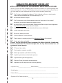
DEALER PRE-DELIVERY CHECK LIST
AFTER COMPLETION, DEALER SHOULD REMOVE AND RETAIN FOR RECORDS
After the Top Shot has been completely set-up, check to be certain it is in correct operating order
before delivering to the customer. The following is a list of points to inspect. Check off each item as
you have made the proper adjustments and found the item operating satisfactorily.
Top Shot was not damaged in shipment. Check for dents and loose or missing parts.
Report damage immediately to H&S Manufacturing Co., Inc.
All bolts and fasteners are tight.
Top Shot has been correctly assembled according to instructions in this manual.
Wheel nuts and all other fasteners are tightly secured.
All grease fittings have been lubricated. Gearboxes are filled to proper levels if applicable.
See Lubrication Chapter of this manual for details.
Hoses and fittings are properly attached and there are no visible leaks.
Guards and shields are secure.
Wheels are properly mounted.
Tires are inflated to correct pressure.
Chains tension is properly adjusted. See Adjustment Chapter of this manual.
Decals are in place and legible.
Connect the Top Shot onto a proper horsepower 540 RPM or 1000 RPM (if applicable)
tractor and attach the PTO. Connect the lights. Run the Top Shot and make sure all
components operate properly.
PTO guard turns freely.
Discharge door operates smoothly.
Main Auger operates up and down smoothly.
Hydraulic system does not leak under pressure.
Lights and wiring functioning properly.
Electronic Scale (if provided) operates properly.
Implement and all components are functioning properly.
-3-
(Remove Dealer File Copy At Perforation)
Inspection Date____________________ Model Number ________________________________
Serial Number______________________________________________
Dealer’s Name ________________________________________________________________
Signature of Pre-Delivery Inspector ________________________________________________

-4-
Intentionally Left Blank

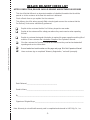
AFTER COMPLETION, DEALER SHOULD REMOVE AND RETAIN FOR RECORDS
This check list that follows is an important reminder of valuable information that should be
passed on to the customer at the time this machine is delivered.
Check off each item as you explain it to the customer.
This delivery check list, when properly filled out and signed assures the customer that the
Pre-Delivery Service was satisfactorily performed.
Explain to the customer that the Pre-Delivery Inspection was made.
Explain to the customer all the safety precautions they must exercise when operating
this unit.
Explain to customer that regular lubrication is required for proper operation and long life of
machine. Show customer the Lubrication Chapter of the Operator’s Manual.
Give the customer the Operator’s Manual and make sure they read and understand all
operating and service instructions.
Record model and serial number on this page and page 38 of this Operators Manual.
Have customer sign a completed “Warranty Registration,” and mail it promptly.
(Remove Dealer File Copy At Perforation)
-5-
DEALER DELIVERY CHECK LIST
Note: Warranty is not valid until warranty card is completed and returned to H&S Mfg. Co., Inc.
Date Delivered __________________________________
Dealer’s Name ________________________________________________________________
By __________________________________________________________________________
Signature of Original Buyer ______________________________________________________

-6-
Intentionally Left Blank

BE
ALERT! YOUR SAFETY
IS INVOLVED.
THIS SYMBOL IS USED THROUGHOUT THIS BOOK WHENEVER YOUR PERSONAL SAFETY
IS INVOLVED. TAKE TIME TO BE CAREFUL. REMEMBER: THE CAREFUL OPERATOR IS
THE BEST OPERATOR. MOST ACCIDENTS ARE CAUSED BY HUMAN ERROR.
CERTAIN PRECAUTIONS MUST BE OBSERVED TO PREVENT THE POSSIBILITY OF INJURY
OR DAMAGE.
-7-
H&S MANUFACTURING CO., INC.
SAFETY INFORMATION

-8-
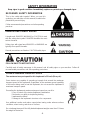
RECOGNIZE SAFETY INFORMATION
This is the safety-alert symbol. When you see this
symbol on your machine or in this manual, be alert to the
potential for personal injury.
Follow recommended precautions and safe operating
practices.
UNDERSTAND SIGNAL WORDS
A single word; DANGER, WARNING, or CAUTION is used
with the safety-alert symbol. DANGER identifies the most
serious hazards.
Safety signs with signal word DANGER or WARNING are
typically near specific hazards.
General precautions are listed on CAUTION safety signs.
FOLLOW SAFETY INSTRUCTIONS
Carefully read all safety messages in this manual, and all safety signs on your machine. Follow all
recommended precautions and safe operating procedures.
SAFETY INFORMATION
OBSERVE MAXIMUM TRANSPORT SPEED
The maximum transport speed for this implement is 32 km/h (20 m.p.h.).
Some tractors are capable of operating at speeds that exceed the maximum
transport speed of this implement. Regardless of the maximum speed capability
of the tractor being used to tow this implement, do not exceed the implement’s
maximum transport speed.
Exceeding the implements maximum transport speed can result in:
* Loss of control of the tractor/implement combination
* Reduced or no ability to stop during braking
* Implement tire failure
* Damage to the implement structure or its components
Use additional caution and reduce speed when towing under adverse surface
conditions, when turning, and when on inclines.
Do not attempt transport if the fully loaded implement weighs more than 1.5 times
the weight of the tractor.
Keep signs in good condition. Immediately replace any missing or damaged signs.

-9-
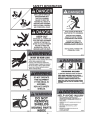
SAFETY INFORMATION

SAFETY INFORMATION
-10-

TRACTORS:
This Operators Manual uses the term “Tractor” when identifying the the power source.
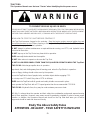
WARNING
TO PREVENT SERIOUS INJURY OR DEATH
Study The Above Safety Rules
ATTENTION - BE ALERT - YOUR SAFETY IS INVOLVED
BEFORE YOU ATTEMPT TO OPERATE THIS EQUIPMENT, READ AND STUDY THE FOLLOWING INFORMATION.
IN ADDITION, MAKE SURE THAT EVERY INDIVIDUAL WHO OPERATES OR WORKS WITH THIS EQUIPMENT,
WHETHER FAMILY MEMBER OR EMPLOYEE, IS FAMILIAR WITH THESE SAFETY PRECAUTIONS.
H&S Mfg. Co. always takes the operator and their safety into consideration and guards exposed moving
parts for their protection. However, some areas cannot be guarded or shielded in order to assure proper
operation. In addition, the Operators Manual and decals on the Top Shot itself warn you of further
danger and should be read and observed closely.
-11-
KNOW HOW TO STOP TOP SHOT BEFORE STARTING IT.
If the Top Shot becomes clogged or for servicing, Stop the tractor engine, remove ignition key and
allow all mechanisms to stop. Before cleaning or working on the Top Shot, detach the PTO shaft, and
completely disengage the tractor hydraulics.
DO NOT attempt to perform maintenance or repair with tractor running, and PTO, and hydraulic hoses
connected to the tractor.
DO NOT step up on the Top Shot at any time while in operation.
NEVER manually feed material into the expeller.
DO NOT allow minors to operate or be near the Top Shot.
DO NOT ALLOW PERSONNEL OTHER THAN THE QUALIFIED OPERATOR NEAR THE Top Shot.
STAY CLEAR of discharge expeller when in operation.
Keep hands, feet, and clothing away from all moving parts when the Top Shot is in operation.
Loose or floppy clothing should not be worn by the operator.
Be sure the Top Shot is clear of people, tools, and other objects before engaging PTO.
Do not step over PTO shaft: Stay clear of PTO at all times.
NEVER start the Top Shot until all guards and safety shields are secured in place.
Never operate the Top Shot with a PTO speed greater than the recommended PTO RPM.
STAY CLEAR of hydraulic lines, they may be under extreme pressure or heat.

-12-

WHEELS & TIRES
The Top Shot may be shipped without the wheels/tires installed.
1. Attach the wheels with tires, using the lug nuts furnished and torque the mounting hardware to
the appropriate torque listed in the Service Chapter. Check wheel bolts periodically thereafter.
2. Inflate the tires to the appropriate pressure listed in the Service Chapter.
3. Check the Top Shot for proper assembly and adjustment and make sure that all bolts are
tightened.
4. Securely retighten after a few hours of operation, as bolts can loosen up on new machinery.
5. Lubricate the Top Shot completely.
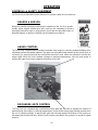
SET-UP & ASSEMBLY
-13-
WARNING: Some photographs used in the following pages show guards or
shields removed for clarification. Never operate machine until these guards
or shields are in proper operating position.
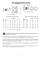
NOTE: Determine right or left side of the Manure Spreader by viewing it from the rear. If instructions
or parts lists call for hardened bolts, refer to the Cap Screw Torque Value page to identify.

TRANSPORTING
SAFETY CHAIN (Optional)
Follow state and local regulations regarding use of a safety chain and transport lighting when towing
farm equipment on public highways. A proper safety chain should be used to retain the safety connection
between the towing and towed machines, in the event of separation of the primary attaching system.
Check with local law enforcement agencies for your own particular regulations. Unless otherwise
prohibited, use a slow-moving vehicle emblem. Never tow the Top Shot on a public highway at a speed
greater than 20 m.p.h. (32 kph).
As required or when desired, the Top Shot can be equipped with a safety chain for travel on public
highways.
1. Chain is sufficiently slack to allow turns and movements of either the tractor or the Top Shot,
without placing tension on the chain.
2. Chain is of sufficient strength to hold the decoupled implement (and its load) and tow it to the
shoulder.
TOWING ON HIGHWAY
To view beyond the back of the larger trailer-mounted Top Shot when transporting the unit on a public
highway, consider obtaining and installing a rear view mirror on your tractor with a wide load mounting
bracket.
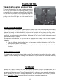
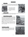
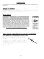
TRANSPORT LIGHTING & REFLECTORS
Transport lighting with a 7 pin plug is standard equipment
on all Top Shot Models. The lighting system is to be
connected to the 7 pin power receptacle (per SAEJ560B)
on your tractor. If your tractor is not equipped with the proper
receptacle, see your tractor dealer for details. Red reflective
safety decals and a SMV sign are on the rear of the tank
for safety.
STORAGE
Because the Top Shot is likely to be used year-round, it should be in ready-to-operate condition at all
times. Several provisions have been designed into the Top Shot to enable it to be used in cold, moderate
and warm outside temperatures. The most important factor for continuous proper operation is lubrication.
When operating the Top Shot in freezing temperatures, the unit should be stored inside, if possible.
Refer to Operation Chapter for special operating procedures in freezing temperatures.
-14-

PREPARING FOR OPERATION
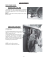
TRACTION CONNECTIONS
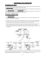
Tractor Hitch
1. The hitch of the Top Shot is designed for a standardized tractor hitch. Adjust the drawbar so that it
is 13 to 17 inches above the ground.
2. Extend or shorten it so that the horizontal distance from the end of the tractor power takeoff shaft to
the center of the hitch pin hole is 15-3/4” for 1000 RPM PTO as shown in drawing. An improperly
located hitch point may cause damage to the universal joints of the power takeoff.
3. Secure the drawbar so that the hitch pin hole is directly below the power drive line. Fasten the Top
Shot to the tractor drawbar with an appropriate hitch pin with safety locking device. After the
connection is made, remove the hitch jack and secure it to the “Storage Position” on the left side of
the Spreader.
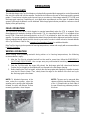
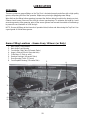
If the Top Shot is attached to a tractor with a clevis
hitch (hammer-strap) style drawbar, the hammer-strap
must be removed to prevent damage to the IID guarding
and the IID telescoping members. [See Figure 1]
If the Top Shot is attached to a tractor with an offset in
the drawbar, be certain it is in the down position to
prevent damage to the IID guarding and the IID
telescoping members. [See Figure 2]
-15-
15-3/4”
PREPARING TOP SHOT
Properly lubricate the Top Shot, check automatic oiler level, and fill if necessary before operating. Refer
to Lubrication Section of this Operator’s Manual for locations.
If theTop Shot is going to be operated in freezing temperatures, review and comply with recommendations
in the Operation Chapter, under the Winter Operation section.
Proper operation of a loaded Top Shot requires a tractor with sufficient horsepower to run the PTO and
proper size to counterbalance the weight of a loaded Top Shot.

PREPARING FOR OPERATION
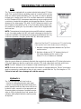
Hydraulics
The Top Shot requires a 4 hose hook-up;
- 2 hoses for raising/lowering the main auger.
- 2 hoses for opening/closing the discharge door.
Before starting the tractor, make sure each set of
hydraulic hoses connects to the appropriate set
of remote outlets on the tractor. Operate the tractor
valve to fill the hydraulic lines and operate the
cylinders. Add hydraulic fluid to the tractor system,
as required.
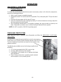
Attach the Top Shot PTO to the tractor PTO shaft locking
it into position and check distance by the following.
1. Maintain a straight alignment between the Top Shot
and the tractor.
2. Maintain a distance of 6”- 12” between the top of
the tractor drawbar and the center of the
tractor PTO. An 8” distance is standard.
After the correct distance is obtained, slide back the coupler lock and attach the PTO drive to the tractor
PTO shaft. Make sure that the coupler locks onto the PTO shaft; slide it back and forth until it locks.
NOTE: Do NOT attempt to use a hammer to help in attaching the PTO drive connection.
NOTE: Remove the tractor 3-point quick hitch if the tractor is equipped with one. Tractor 3-point arms
must be removed or positioned so they do not come in contact with the Top Shot tongue or PTO.
Failure to heed will cause damage and void the warranty.
PTO
The Top Shot is equipped with a constant velocity telescoping PTO drive
shaft. This constant velocity capability, results in a smooth, quiet running
drive line, without power fluctuation. The Top Shot can only be properly
hooked-up to a tractor which has PTO and hitch dimensions conforming
to ASAE Standard S203. Horsepower required may vary according to the
consistency of material to be spread, ground speed and terrain. To prevent
damage to the telescoping PTO drive, DO NOT allow the tractor’s rear
tires to make contact with the PTO or Top Shot while making sharp turns,
Be careful when pulling the Top Shot with a tractor that is equipped with
dual rear tires.
NOTE: The maximum joint angle must not exceed 80º whether in operation
or not. Any angle greater than 80º, will result in damage to the joint. For
continuous operation, the maximum joint angle must be limited to 35º. Any
continuous operation, at angles greater than 35º, will shorten joint life.
-16-

OPERATION
EMERGENCY SHUTDOWN
In case a foreign object becomes lodged in the expeller or
auger area, disengage the PTO. Stop the tractor engine,
remove ignition key, and allow all mechanisms to stop
before cleaning or working on the machine. If an object is
lodged inside the tank, block-up the discharge gate and raise
the conveyor auger before attempting to remove the object.
GENERAL INFORMATION
Check entire Top Shot carefully before first operation. Tighten bolts and set screws that might have
come loose in shipping. Lubricate as explained in the Lubrication Chapter in this manual.
H&S Top Shots feature a large tank, forward right side discharge expeller, hydraulically controlled
discharge gate, and conveyor auger. Top Shots are designed and constructed to handle a wide variety of
waste material types including liquids, semi-liquids, and limited solid material. Many potential spreading
problems can be avoided if the following guidelines are established and met:
NOTE: To prevent damage to the expeller, auger and drive line, foreign objects, such as stones,
timber or metal, should never be placed into the Top Shot tank.
1. In winter or freezing temperatures, make sure the auger and expeller are free to rotate and that
the discharge gate moves freely, before loading the Top Shot and applying PTO power.
2. The discharge gate must be closed before loading.
3. The auger is completely lowered before loading.
4. When loading packed material into the Top Shot with a loader bucket, try to break up any large
chunks.
5. Material which is too thick or solid to flow should only be heaped on the rear 2/3 of the Top Shot.
6. When hauling extremely heavy materials with a large portion of dirt, it may be necessary to reduce
the load size to prevent excessive shear bolt breakage. Do not use extra sideboards. Do not
overload the Top Shot. Overloading decreases spreading effectiveness.
7. Liquid or semi-liquids that flow will self-level allowing the Top Shot to be filled to a level such that
sloshing or splashing material will be contained.
NOTE: Expeller feeding will diminish as bridging occurs. To counteract bridging, completely raise, and
lower the auger back down immediately. This operation will help to break-up the bridging.
-17-

FIELD OPERATION
The Top Shot is “direct drive” which begins to operate immediately when the PTO is engaged. Drive
disengagement is made by shutting-off the tractor PTO. It is important that the PTO is engaged at low
tractor RPM. Shear bolt overload protection on the PTO is provided for both the main auger and the
expeller. For proper operation, establish and maintain the proper driveline alignment and tractor hookup.
Before loading material, adjust the hitch clevis to your tractor in order to obtain a level or forward attitude
of the Top Shot tank. Refer to the Preparing For Operation Chapter for additional details.
If the Top Shot is going to be operated in freezing temperatures, review and comply with recommendations
in Winter Operation.
WINTER OPERATION
When loading and spreading material during winter or in freezing temperatures, the following
recommendations apply:
1. After the Top Shot is unloaded and will not be used for some time, follow the EMERGENCY
SHUTDOWN PROCEDURE, then scrape away any solid material remaining on the inside of
the tank or Expeller area.
2. Park the Top Shot with the auger fully raised, the discharge gate fully raised and blocked.
Position the jack height so that liquids will run forward to the discharge opening.
3. Before loading the Top Shot again, unblock the discharge gate and engage the expeller to make
sure that it is free to rotate. Then, slowly lower the auger to the bottom of the tank and cycle
the discharge gate a few times.
OPERATION
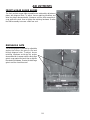
APPLICATION RATE
The side discharge style Top Shot features a hydraulically operated discharge gate to control the material
flow out of the tank and into the expeller. Several factors influence the rate of discharge and the spread
pattern. These factors include: ground speed, type or consistency of discharge material, PTO RPM, and
discharge gate opening. Depending on your application requirements and the type of material being
spread, a full range of patterns can be obtained. A discharge gate indicator provides a continuous visual
display of the gate opening.
-18-
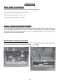
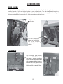
NOTE: To eliminate freeze-up in the
area under the expeller, open the
expeller pan by pushing the trip handle
forward, the pan will release. Before
resuming operation, close the pan.
NOTE: The pan can be removed after
release of the trip handle by lifting it out
of the U-Shaped slots on each side of
the pan if freeze-up problems persist in
this area.
Page is loading ...
Page is loading ...
Page is loading ...
Page is loading ...
Page is loading ...
Page is loading ...
Page is loading ...
Page is loading ...
Page is loading ...
Page is loading ...
Page is loading ...
Page is loading ...
Page is loading ...
Page is loading ...
Page is loading ...
Page is loading ...
Page is loading ...
Page is loading ...
Page is loading ...
Page is loading ...
-
 1
1
-
 2
2
-
 3
3
-
 4
4
-
 5
5
-
 6
6
-
 7
7
-
 8
8
-
 9
9
-
 10
10
-
 11
11
-
 12
12
-
 13
13
-
 14
14
-
 15
15
-
 16
16
-
 17
17
-
 18
18
-
 19
19
-
 20
20
-
 21
21
-
 22
22
-
 23
23
-
 24
24
-
 25
25
-
 26
26
-
 27
27
-
 28
28
-
 29
29
-
 30
30
-
 31
31
-
 32
32
-
 33
33
-
 34
34
-
 35
35
-
 36
36
-
 37
37
-
 38
38
-
 39
39
-
 40
40


H&S TS5134 Operating instructions
- Category
- Spreader
- Type
- Operating instructions
Ask a question and I''ll find the answer in the document
Finding information in a document is now easier with AI
Related papers
-
 H&S TS5242 Operating instructions
-
 H&S TS5242 Operating instructions
-
 H&S TS5234 Operating instructions
-
 H&S TS5220 Operating instructions
-
 H&S TS5215 Operating instructions
-
 H&S TS5215 Operating instructions
-
 H&S TS5242 Operating instructions
-
 H&S TS5215 Operating instructions
-
 H&S TS5220 Operating instructions
-
 H&S TS5234 Operating instructions


Other documents
-
Meyer 5570 Industrial Series Super Spreader Owner's manual
-
-
-
-
-
 PRONAR N161 Owner's manual
-
AGI HX2 16" Series User manual
-
-
-
