Scotsman FME2400RH User manual
- Category
- Ice cube makers
- Type
- User manual
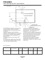
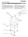
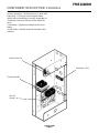
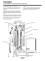
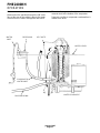
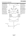
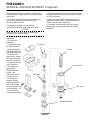
Scotsman FME2400RH is a commercial ice machine designed to be connected to the condensing section of a refrigeration system. It produces flake ice and has a storage capacity of up to 90 pounds. The FME2400RH is suitable for indoor installations in controlled environments with air temperatures between 50°F and 100°F and water temperatures between 40°F and 100°F. It requires a 208-230V/60/1 electrical connection with a minimum circuit ampacity of 2.7 and a maximum fuse size of 15. The unit is equipped with a control box that manages the electrical sequence and operation of the machine.
Scotsman FME2400RH is a commercial ice machine designed to be connected to the condensing section of a refrigeration system. It produces flake ice and has a storage capacity of up to 90 pounds. The FME2400RH is suitable for indoor installations in controlled environments with air temperatures between 50°F and 100°F and water temperatures between 40°F and 100°F. It requires a 208-230V/60/1 electrical connection with a minimum circuit ampacity of 2.7 and a maximum fuse size of 15. The unit is equipped with a control box that manages the electrical sequence and operation of the machine.


-
 1
1
-
 2
2
-
 3
3
-
 4
4
-
 5
5
-
 6
6
-
 7
7
-
 8
8
-
 9
9
-
 10
10
-
 11
11
-
 12
12
-
 13
13
-
 14
14
-
 15
15
-
 16
16
-
 17
17
-
 18
18
-
 19
19
-
 20
20
-
 21
21
-
 22
22
-
 23
23
-
 24
24


Scotsman FME2400RH User manual
- Category
- Ice cube makers
- Type
- User manual
Scotsman FME2400RH is a commercial ice machine designed to be connected to the condensing section of a refrigeration system. It produces flake ice and has a storage capacity of up to 90 pounds. The FME2400RH is suitable for indoor installations in controlled environments with air temperatures between 50°F and 100°F and water temperatures between 40°F and 100°F. It requires a 208-230V/60/1 electrical connection with a minimum circuit ampacity of 2.7 and a maximum fuse size of 15. The unit is equipped with a control box that manages the electrical sequence and operation of the machine.
Ask a question and I''ll find the answer in the document
Finding information in a document is now easier with AI
Related papers
-
Scotsman EPR Setting - 17-3570-01 Operating instructions
-
-
-
-
-
-
-
-
Scotsman FME1200RL User manual
-