Page is loading ...

Introduction
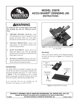
The Model D3994 Mounting Attachment enables
the Model D3978 Accu-Sharp Jig to be mount-
ed on a grinder
1
⁄2" tool rest bar, as shown in
Figure 1.
Figure 1. Model D3994 Mounting Attachment
attached to Model D3978 Accu-Sharp Jig.
Accu-Sharp Jig
Mounting
Attachment
Tool Rest
Bar
Inventory
Bag Contents (Figure 2) Qty
A. Mounting Attachment ................................. 1
B. Cap Screws M5-.8 x 12 .............................. 5
C. Hex Wrench 4mm ....................................... 1
• Read and understand your grinder own-
er's manual and the D3978 instructions,
and follow all of the included safety pre-
cautions and instructions.
• Make sure the mounting attachment is
firmly secured to the auxiliary table of the
D3978 jig and to the grinder tool rest bar
before beginning operation.
Figure 2. Shipping inventory.
A
B
C
MODEL D3994
ACCU-SHARP
®
MOUNTING
ATTACHMENT
INSTRUCTIONS
COPYRIGHT © OCTOBER, 2012 BY WOODSTOCK INTERNATIONAL, INC.
WARNING: NO PORTION OF THIS MANUAL MAY BE REPRODUCED IN ANY SHAPE OR FORM WITHOUT
THE WRITTEN APPROVAL OF WOODSTOCK INTERNATIONAL, INC.
Printed in China#15419TS

-2-
D3994 Instructions
Assembly
1. Lay the auxiliary table of the Model D3978
Accu-Sharp Jig upside down on a stable sur-
face (see Figure 3).
Auxiliary Table
(Upside Down)
Mounting
Attachment
Figure 3. Installing mounting attachment to
auxiliary table.
2. Position the mounting attachment on the
auxiliary table, as illustrated in Figure 3, then
secure it in place with (3) of the provided cap
screws.
Mounting
1. Slide the grinder tool bar rest into the side
hole of the mounting attachment, as illus-
trated in Figure 4.
Cap Screws
Tool Rest Bar
Figure 4. Securing the mounting attachment to
grinder tool rest bar.
2. Loosely thread the (2) remaining cap
screws into the mounting attachment (see
Figure 4).
3. Rotate the assembly around the tool rest bar
so that the auxiliary table is facing up.
4. Properly position it on the grinder for your
operation, then fully tighten the cap screws
used in Step 2 to hold the assembly in
place.
5. Follow the Model D3978 instructions for using
the jig with your grinder.
/

