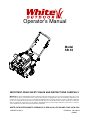
White Outdoor Snow Blower SB 45 User manual
- Category
- Snow throwers
- Type
- User manual
This manual is also suitable for
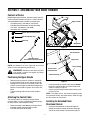
White Outdoor Snow Blower SB 45 is a powerful machine designed to help you tackle even the toughest snowfalls. With its reliable engine and efficient auger system, it can clear snow quickly and effectively. The adjustable discharge chute allows you to direct the snow where you want it, making it easy to keep your walkways and driveway clear. Its compact size makes it easy to maneuver, even in tight spaces. Trust the SB 45 to make your snow removal tasks a breeze.
White Outdoor Snow Blower SB 45 is a powerful machine designed to help you tackle even the toughest snowfalls. With its reliable engine and efficient auger system, it can clear snow quickly and effectively. The adjustable discharge chute allows you to direct the snow where you want it, making it easy to keep your walkways and driveway clear. Its compact size makes it easy to maneuver, even in tight spaces. Trust the SB 45 to make your snow removal tasks a breeze.


-
 1
1
-
 2
2
-
 3
3
-
 4
4
-
 5
5
-
 6
6
-
 7
7
-
 8
8
-
 9
9
-
 10
10
-
 11
11
-
 12
12
-
 13
13
-
 14
14
-
 15
15
-
 16
16


White Outdoor Snow Blower SB 45 User manual
- Category
- Snow throwers
- Type
- User manual
- This manual is also suitable for
White Outdoor Snow Blower SB 45 is a powerful machine designed to help you tackle even the toughest snowfalls. With its reliable engine and efficient auger system, it can clear snow quickly and effectively. The adjustable discharge chute allows you to direct the snow where you want it, making it easy to keep your walkways and driveway clear. Its compact size makes it easy to maneuver, even in tight spaces. Trust the SB 45 to make your snow removal tasks a breeze.
Ask a question and I''ll find the answer in the document
Finding information in a document is now easier with AI
Related papers
Other documents
-
MTD E162 User manual
-
PowerSmart DB7127 User guide
-
Bolens 31AS2P5C565 Owner's manual
-
Remington RM2120 User guide
-
MTD Series 140 through E173 User manual
-
-
Troy-Bilt Squall 521 Owner's manual
-
MTD 2B5 User manual
-
-
Yard Machines Yard Machines E152 Series User manual