Page is loading ...

OM-CWP-20-06-2011
June 2011
Effective with Serial Number 080409
IMPORTANT
Read this manual carefully before installing,
commissioning or operating this product.
Miller Welding Automation, 281 E. Lies Rd., Carol Stream, Il 60188
Telephone: (949) 951-1515 • Fax: (949) 951-9237
Web Site: www.jetline.com • E-mail: [email protected]
OPERATION MANUAL
for
Model CWP-20
Precision Lathe

CWP-20 Precision Lathe
- ii -
Components or parts manufactured directly by Miller Electric Mfg. Co. are subject to Miller’s True Blue® Warranty set forth
at www.millerwelds.com/support/warranty. Seller does not make any warranties for components or parts not
manufactured directly by Jetline Engineering, Miller Welding Automation, and Panasonic Welding Systems Company; such
components or parts are subject to the warranty terms of the respective manufacturer. Components and parts
manufactured by Jetline Engineering, Miller Welding Automation, and Panasonic Welding Systems Company are subject to
the following warranty terms. Terms and Conditions of Sale Seller warrants to Purchaser that the components or parts
manufactured by Seller or Panasonic Welding Systems Company shall be free from defects in material and workmanship,
and shall conform to the Seller’s specifications for the following periods:
a. 12 months from the date of shipment of the Products for components and equipment manufactured by
Panasonic Welding Systems Company including robot manipulator, controller and connecting cables; external axis
components (external axis base unit, servo amplifiers, motors, connecting cables and pre-engineered positioners);
peripheral devices (high voltage touch sensors, thru arc seam trackers); welding power sources (internally built
into the robot controller cabinet); wire feeders (separated design or integrated design, i.e. Active Wire
Torch/Feeder); or
b. 12 months from date of shipment of the Products for equipment manufactured by Jetline Engineering or Miller
Welding Automation.
In the event of a breach of the warranties set forth above, Seller will, at Seller’s option and as Seller’s sole liability and
Purchaser’s sole remedy, repair, replace or credit Purchaser’s account for, any Product that fails to conform to the above
warranty, provided that (i) during the applicable warranty period Seller is promptly notified in writing upon discovery of
such failure with a detailed explanation of any alleged deficiencies; (ii) Seller is given a reasonable opportunity to
investigate all claims; and (iii) Seller’s examination of such Product confirms the alleged deficiencies and that the
deficiencies were not caused by accident, misuse, neglect, improper installment, unauthorized alteration or repair or
improper testing. No Products may be returned to Seller until inspection and approval by Seller. All warranty work
performed shall be FOB Seller’s facility (Incoterms 2010) and freight for returned Products shall be paid for by Purchaser.
The above warranty against defects does not apply to: (1) consumable components or ordinary wear items including but
not limited to torches; or (2) defects due to (i) failure to install and perform maintenance set forth in Product
documentation, (ii) the use of components, parts, peripherals, attachments, accessories, or perishable tooling not
approved by Seller, (iii) accident, misuse, neglect, abuse, mishandling, misapplication, modification, alteration, acts of God,
or (iv) improper installation, service or maintenance. Purchaser and/or the operator of the Products are in full control of
the weld process. Seller makes no warranty regarding the quality or the success of the welds on the Products due to
factors under Purchaser’s and/or operator’s control including but not limited to welding procedures, material types,
material coatings, joint/part fit, part geometry, metallurgy, welding gases, proper machine/process maintenance, and
operator skill. EXCEPT AS SET FORTH ABOVE, SELLER MAKES NO WARRANTY OR REPRESENTATION OF ANY KIND, EXPRESS
OR IMPLIED (INCLUDING NO WARRANTY OF MERCHANTABILITY OR FITNESS FOR ANY PARTICULAR PURPOSE).
- See more at: https://www.millerwelds.com/automation-terms-of-sale#sthash.l5oRebWB.dpuf
LIMITED WARRANTY

- iii -
CWP-20 Precision Lathe
NOTICE
The installation, operation and maintenance guidelines set out in this manual will enable you to
maintain the equipment in peak condition and achieve maximum efficiency with your welding
operation. Please read these instructions carefully to become aware of every advantage.
CAUTION
Only experienced personnel familiar
with the operation and safe practice of
welding equipment should install
and/or use
this equipment.

CWP-20 Precision Lathe
4
CONTENTS
Section I ..................................................................................................................................................................... 1
SAFETY PRECAUTIONS – READ BEFORE USING ............................................................................................... 1
1.1 Symbol Usage .................................................................................................................................................. 1
1.2 Arc Welding Hazards ....................................................................................................................................... 1
1.3 Additional Symbols for Installation, Operation, And Maintenance ................................................................ 4
1.4 California Proposition 65 Warnings ................................................................................................................ 6
1.5 Principal Safety Standards .............................................................................................................................. 6
1.6 EMF Information ............................................................................................................................................. 6
Section II .................................................................................................................................................................... 7
Introduction .............................................................................................................................................................. 7
Section III ................................................................................................................................................................... 9
Initial Inspection ........................................................................................................................................................ 9
Section IV ................................................................................................................................................................11
Specifications ..........................................................................................................................................................11
Section V .................................................................................................................................................................12
Mechanical Installation ...........................................................................................................................................12
Section VI ................................................................................................................................................................13
Electrical Installation ...............................................................................................................................................13
Section VII ...............................................................................................................................................................14
Operation ................................................................................................................................................................14
A. Lathe Bed ....................................................................................................................................................14
B. Headstock Assembly....................................................................................................................................14
C. Tailstock ......................................................................................................................................................14
D. Vertical Slide and Carriage Assembly ..........................................................................................................14
E. Lathe Chucks ...............................................................................................................................................16
F. 9700T Rotation Control ...............................................................................................................................16
G. Sequence of Operation ...............................................................................................................................16
Section VIII ..............................................................................................................................................................17
Trouble Shooting .....................................................................................................................................................17
B. GTAW Process .................................................................................................................................................18
C. GMAW Process ...............................................................................................................................................19
Section IX .................................................................................................................................................................21

CWP-20 Precision Lathe
5
Maintenance ...........................................................................................................................................................21
A. Mechanical Adjustments .............................................................................................................................21
Section X ..................................................................................................................................................................22
Parts List ..................................................................................................................................................................22

1
SECTION I
SAFETY PRECAUTIONS – READ BEFORE USING
(som 2013-09)
1.1 Symbol Usage
DANGER! − Indicates a hazardous situation which, if not avoided, will result in death or serious injury. The possible hazards are shown in the
adjoining symbols or explained in the text.
Indicates a hazardous situation which, if not avoided, could result in death or serious injury. The possible hazards are shown in the adjoining symbols or
explained in the text.
NOTICE − Indicates statements not related to personal injury.
Indicates special instructions.
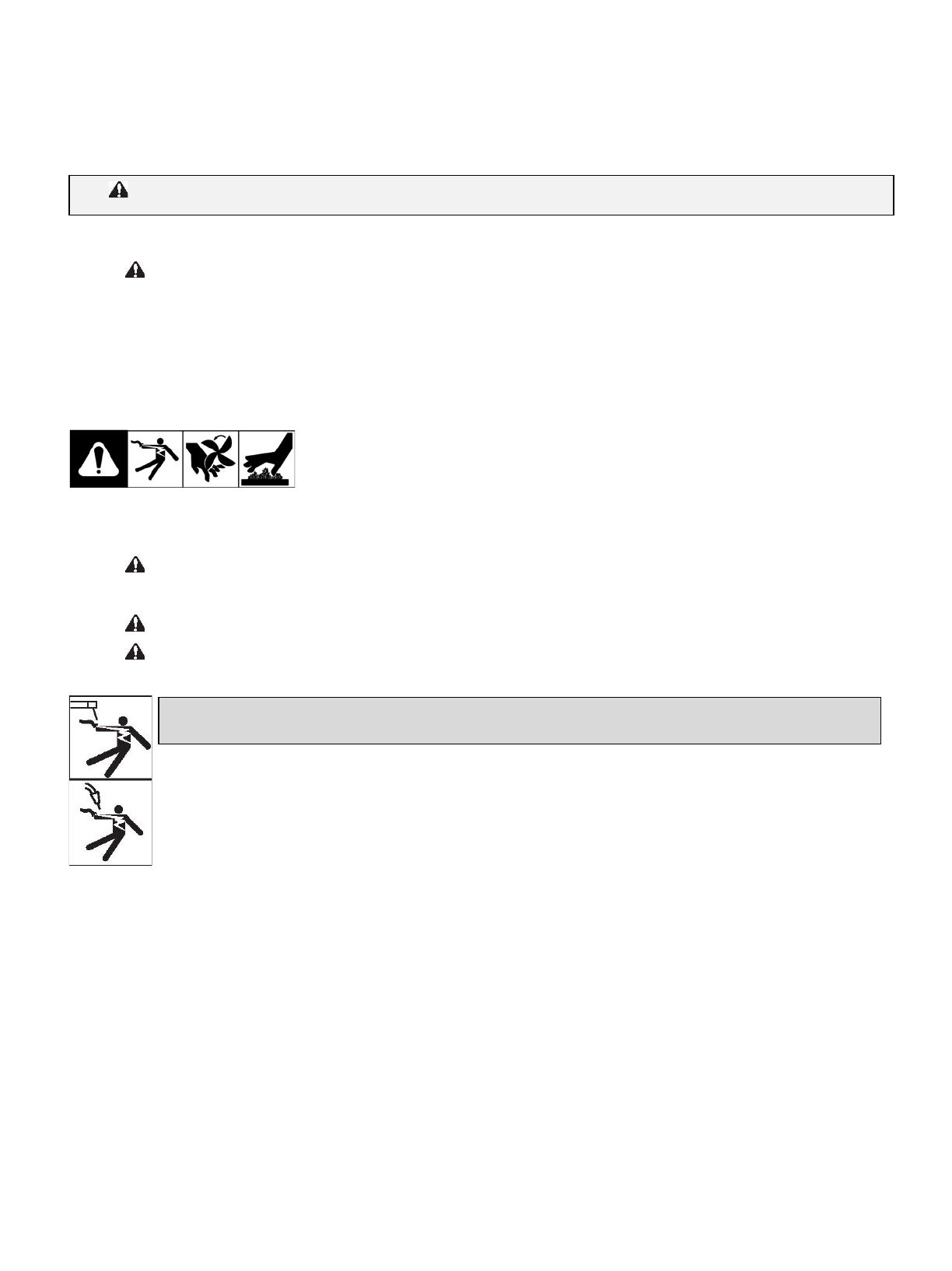
This group of symbols means: Warning! Watch Out! ELECTRIC SHOCK, MOVING PARTS, and HOT PARTS hazards.
Consult symbols and related instructions below for necessary actions to avoid the hazards.
1.2 Arc Welding Hazards
The symbols shown below are used throughout this manual to call attention to and identify possible hazards. When you see the symbol,
watch out, and follow the related instructions to avoid the hazard. The safety information given below is only a summary of the more
complete safety information found in the Safety Standards listed in Section 1-5. Read and follow all Safety Standards.
Only qualified persons should install, operate, maintain, and repair this unit.
During operation, keep everybody, especially children, away.
Touching live electrical parts can cause fatal shocks or severe burns. The electrode and work circuit is electrically live whenever the output is
on. The input power circuit and machine internal circuits are also live when power is on. In semiautomatic or automatic wire welding, the wire,
wire reel, drive roll housing, and all metal parts touching the welding wire are electrically live. Incorrectly installed or improperly grounded
equipment is a hazard.
• Do not touch live electrical parts.
• Wear dry, hole-free insulating gloves and body protection.
• Insulate yourself from work and ground using dry insulating mats or covers big enough to prevent any physical contact with the work
or ground.
• Do not use AC output in damp areas, if movement is confined, or if there is a danger of falling.
• Use AC output ONLY if required for the welding process.
• If AC output is required, use remote output control if present on unit.
• Additional safety precautions are required when any of the following electrically hazardous conditions are present: in damp locations
or while wearing wet clothing; on metal structures such as floors, gratings, or scaffolds; when in cramped positions such as sitting,
kneeling, or lying; or when there is a high risk of unavoidable or accidental contact with the work piece or ground. For these
conditions, use the following equipment in order presented: 1) a semiautomatic DC constant voltage (wire) welder, 2) a DC manual
(stick) welder, or 3) an AC welder with reduced open-circuit voltage. In most situations, use of a DC, constant voltage wire welder is
recommended. And, do not work alone!
• Disconnect input power or stop engine before installing or servicing this equipment. Lockout/tagout input power according to OSHA
29 CFR 1910.147 (see Safety Standards).
• Properly install, ground, and operate this equipment according to its Owner’s Manual and national, state, and local codes.
• Always verify the supply ground − check and be sure that input power cord ground wire is properly connected to ground terminal in
disconnect box or that cord plug is connected to a properly grounded receptacle outlet.
• When making input connections, attach proper grounding conductor first − double-check connections.
• Keep cords dry, free of oil and grease, and protected from hot metal and sparks.
• Frequently inspect input power cord and ground conductor for damage or bare wiring – replace immediately if damaged – bare
wiring can kill.
• Turn off all equipment when not in use.
• Do not use worn, damaged, undersized, or repaired cables.
Protect yourself and others from injury – read, follow and save these important safety precautions and operating instructions.
ELECTRIC SHOCK can kill.
CWP-20 Precision Lathe
2
• Do not drape cables over your body.
• If earth grounding of the workpiece is required, ground it directly with a separate cable.
• Do not touch electrode if you are in contact with the work, ground, or another electrode from a different machine.
• Do not touch electrode holders connected to two welding machines at the same time since double open-circuit voltage will be
present.
• Use only well-maintained equipment. Repair or replace damaged parts at once. Maintain unit according to manual.
• Wear a safety harness if working above floor level.
• Keep all panels and covers securely in place.
• Clamp work cable with good metal-to-metal contact to workpiece or worktable as near the weld as practical.
• Insulate work clamp when not connected to workpiece to prevent contact with any metal object.
• Do not connect more than one electrode or work cable to any single weld output terminal. Disconnect cable for process not in use.
• Use GFCI protection when operating auxiliary equipment in damp or wet locations.
SIGNIFICANT DC VOLTAGE exists in inverter welding power sources AFTER removal of input power.
• Turn Off inverter, disconnect input power, and discharge input capacitors according to instructions in Maintenance Section before
touching any parts.
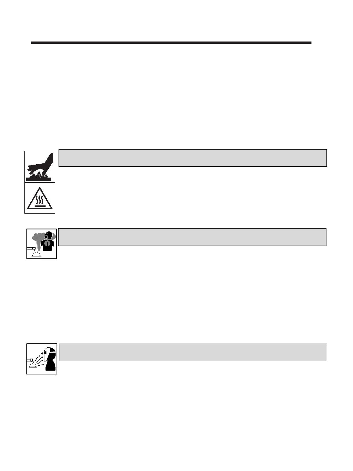
• Do not touch hot parts bare handed.
• Allow cooling period before working on equipment.
• To handle hot parts, use proper tools and/or wear heavy, insulated welding gloves and clothing to prevent burns.
Welding produces fumes and gases. Breathing these fumes and gases can be hazardous to your health.
• Keep your head out of the fumes. Do not breathe the fumes.
• If inside, ventilate the area and/or use local forced ventilation at the arc to remove welding fumes and gases. The recommended way
to determine adequate ventilation is to sample for the composition and quantity of fumes and gases to which personnel are
exposed.
• If ventilation is poor, wear an approved air-supplied respirator.
• Read and understand the Safety Data Sheets (SDSs) and the manufacturer’s instructions for adhesives, coatings, cleaners,
consumables, coolants, degreasers, fluxes, and metals.
• Work in a confined space only if it is well ventilated, or while wearing an air-supplied respirator. Always have a trained watch-person
nearby. Welding fumes and gases can displace air and lower the oxygen level causing injury or death. Be sure the breathing air is
safe.
• Do not weld in locations near degreasing, cleaning, or spraying operations. The heat and rays of the arc can react with vapors to
form highly toxic and irritating gases.
• Do not weld on coated metals, such as galvanized, lead, or cadmium plated steel, unless the coating is removed from the weld area,
the area is well ventilated, and while wearing an air-supplied respirator. The coatings and any metals containing these elements can
give off toxic fumes if welded.
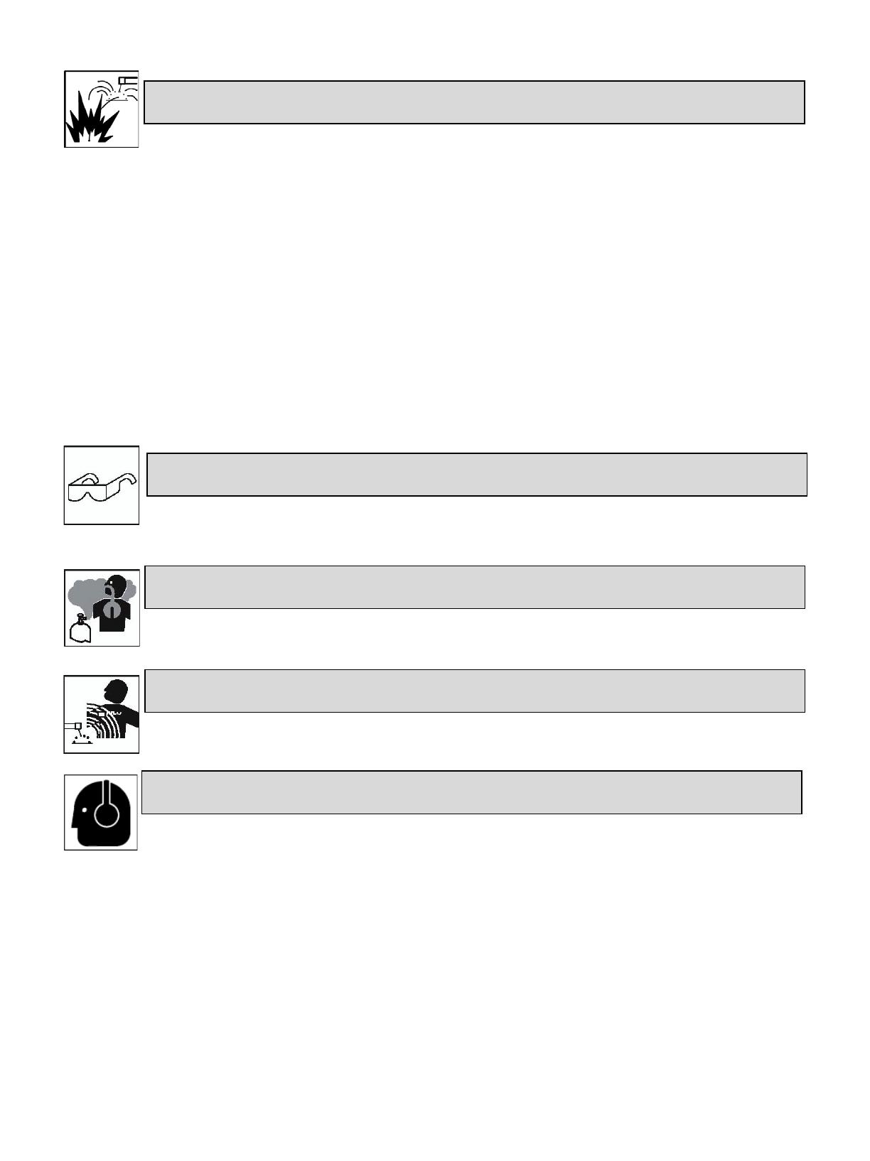
Arc rays from the welding process produce intense visible and invisible (ultraviolet and infrared) rays that can burn eyes and skin. Sparks fly off
from the weld.
• Wear an approved welding helmet fitted with a proper shade of filter lenses to protect your face and eyes from arc rays and sparks
when welding or watching (see ANSI Z49.1 and Z87.1 listed in Safety Standards).
• Wear approved safety glasses with side shields under your helmet.
• Use protective screens or barriers to protect others from flash,glare and sparks; warn others not to watch the arc.
• Wear body protection made from durable, flame−resistant material (leather, heavy cotton, wool). Body protection includes oil-free
clothing such as leather gloves, heavy shirt, cuffless trousers, high shoes, and a cap.
HOT PARTS can burn.
ARC RAYS can burn eyes and skin.
FUMES AND GASES can be hazardous.
3
Welding on closed containers, such as tanks, drums, or pipes, can cause them to blow up. Sparks can fly off from the welding arc. The flying
sparks, hot workpiece, and hot equipment can cause fires and burns. Accidental contact of electrode to metal objects can cause sparks,
explosion, overheating, or fire. Check and be sure the area is safe before doing any welding.
• Remove all flammables within 35 ft (10.7 m) of the welding arc. If this is not possible, tightly cover them with approved covers.
• Do not weld where flying sparks can strike flammable material.
• Protect yourself and others from flying sparks and hot metal.
• Be alert that welding sparks and hot materials from welding can easily go through small cracks and openings to adjacent areas.
• Watch for fire, and keep a fire extinguisher nearby.
• Be aware that welding on a ceiling, floor, bulkhead, or partition can cause fire on the hidden side.
• Do not weld on containers that have held combustibles, or on closed containers such as tanks, drums, or pipes unless they are
properly prepared according to AWS F4.1 and AWS A6.0 (see Safety Standards).
• Do not weld where the atmosphere may contain flammable dust, gas, or liquid vapors (such as gasoline).
• Connect work cable to the work as close to the welding area as practical to prevent welding current from traveling long, possibly
unknown paths and causing electric shock, sparks, and fire hazards.
• Do not use welder to thaw frozen pipes.
• Remove stick electrode from holder or cut off welding wire at contact tip when not in use.
• Wear body protection made from durable, flame−resistant material (leather, heavy cotton, wool). Body protection includes oil-free
clothing such as leather gloves, heavy shirt, cuffless trousers, high shoes, and a cap.
• Remove any combustibles, such as a butane lighter or matches, from your person before doing any welding.
• After completion of work, inspect area to ensure it is free of sparks, glowing embers, and flames.
• Use only correct fuses or circuit breakers. Do not oversize or bypass them.
• Follow requirements in OSHA 1910.252 (a) (2) (iv) and NFPA 51B for hot work and have a fire watcher and extinguisher nearby.
Read and understand the Safety Data Sheets (SDSs) and the manufacturer’s instructions for adhesives, coatings, cleaners, consumables,
coolants, degreasers, fluxes, and metals.
• Welding, chipping, wire brushing, and grinding cause sparks and flying metal. As welds cool, they can throw off slag.
• Wear approved safety glasses with side shields even under your welding helmet.
• Shut off compressed gas supply when not in use.
• Always ventilate confined spaces or use approved air-supplied respirator.
• Wearers of Pacemakers and other Implanted Medical Devices should keep away.
• Implanted Medical Device wearers should consult their doctor and the device manufacturer before going near arc welding, spot
welding, gouging, plasma arc cutting, or induction heating operations.
• Noise from some processes or equipment can damage hearing.
• Wear approved ear protection if noise level is high.
WELDING can cause fire or explosion.
FLYING METAL or DIRT can injure eyes.
BUILDUP OF GAS can injure or kill.
ELECTRIC AND MAGNETIC FIELDS (EMF) can affect Implanted Medical Devices.
NOISE can damage hearing.
CWP-20 Precision Lathe
4
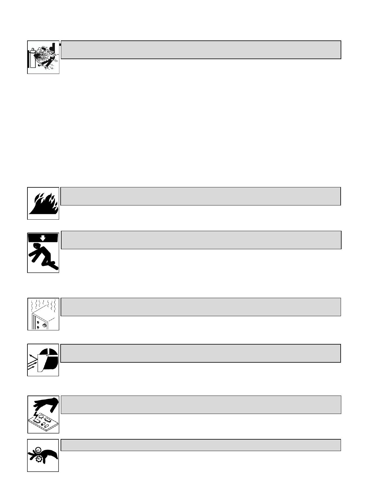
Compressed gas cylinders contain gas under high pressure. If damaged, a cylinder can explode. Since gas cylinders are normally part of the
welding process, be sure to treat them carefully.
• Protect compressed gas cylinders from excessive heat, mechanical shocks, physical damage, slag, open flames, sparks, and arcs.
• Install cylinders in an upright position by securing to a stationary support or cylinder rack to prevent falling or tipping.
• Keep cylinders away from any welding or other electrical circuits.
• Never drape a welding torch over a gas cylinder.
• Never allow a welding electrode to touch any cylinder.
• Never weld on a pressurized cylinder − explosion will result.
• Use only correct compressed gas cylinders, regulators, hoses, and fittings designed for the specific application; maintain them and
associated parts in good condition.
• Turn face away from valve outlet when opening cylinder valve. Do not stand in front of or behind the regulator when opening the
valve.
• Keep protective cap in place over valve except when cylinder is in use or connected for use.
• Use the right equipment, correct procedures, and sufficient number of persons to lift and move cylinders.
• Read and follow instructions on compressed gas cylinders, associated equipment, and Compressed Gas Association (CGA) publication
P-1 listed in Safety Standards.
1.3 Additional Symbols for Installation, Operation, And Maintenance
• Do not install or place unit on, over, or near combustible surfaces.
• Do not install unit near flammables.
• Do not overload building wiring − be sure power supply system is properly sized, rated, and protected to handle this unit.
• Use lifting eye to lift unit only, NOT running gear, gas cylinders, or any other accessories.
• Use equipment of adequate capacity to lift and support unit.
• If using lift forks to move unit, be sure forks are long enough to extend beyond opposite side of unit.
• Keep equipment (cables and cords) away from moving vehicles when working from an aerial location.
• Follow the guidelines in the Applications Manual for the Revised NIOSH Lifting Equation (Publication No. 94−110) when manually
lifting heavy parts or equipment.
• Allow cooling period; follow rated duty cycle.
• Reduce current or reduce duty cycle before starting to weld again.
• Do not block or filter airflow to unit.
• Wear a face shield to protect eyes and face.
• Shape tungsten electrode only on grinder with proper guards in a safe location wearing proper face, hand, and body protection.
• Sparks can cause fires — keep flammables away.
• Put on grounded wrist strap BEFORE handling boards or parts.
• Use proper static-proof bags and boxes to store, move, or ship PC boards.
CYLINDERS can explode if damaged.
FIRE OR EXPLOSION hazard.
FALLING EQUIPMENT can injure.
OVERUSE can cause OVERHEATING
FLYING SPARKS can injure.
STATIC (ESD) can damage PC boards.
MOVING PARTS can injure.
5
• Keep away from moving parts.
• Keep away from pinch points such as drive rolls.
• Do not press gun trigger until instructed to do so.
• Do not point gun toward any part of the body, other people, or any metal when threading welding wire.
• Do not use welder to charge batteries or jump start vehicles unless it has a battery charging feature designed for this purpose.
• Keep away from moving parts such as fans.
• Keep all doors, panels, covers, and guards closed and securely in place.
• Have only qualified persons remove doors, panels, covers, or guards for maintenance and troubleshooting as necessary.
• Reinstall doors, panels, covers, or guards when maintenance is finished and before reconnecting input power.
• Read and follow all labels and the Owner’s Manual carefully before installing, operating, or servicing unit. Read the safety
information at the beginning of the manual and in each section.
• Use only genuine replacement parts from the manufacturer.
• Perform maintenance and service according to the Owner’s Manuals, industry standards, and national, state, and local codes.
• High-frequency (H.F.) can interfere with radio navigation, safety services, computers, and communications equipment.
• Have only qualified persons familiar with electronic equipment perform this installation.
• The user is responsible for having a qualified electrician promptly correct any interference problem resulting from the installation.
• If notified by the FCC about interference, stop using the equipment at once.
• Have the installation regularly checked and maintained.
• Keep high-frequency source doors and panels tightly shut, keep spark gaps at correct setting, and use grounding and shielding to
minimize the possibility of interference.
• Electromagnetic energy can interfere with sensitive electronic equipment such as computers and computer-driven equipment such
as robots.
• Be sure all equipment in the welding area is electromagnetically compatible.
• To reduce possible interference, keep weld cables as short as possible, close together, and down low, such as on the floor.
• Locate welding operation 100 meters from any sensitive electronic equipment.
• Be sure this welding machine is installed and grounded according to this manual.
• If interference still occurs, the user must take extra measures such as moving the welding machine, using shielded cables, using line
filters, or shielding the work area.
WELDING WIRE can injure.
BATTERY EXPLOSION can injure.
MOVING PARTS can injure.
READ INSTRUCTIONS.
H.F. RADIATION can cause interference.
ARC WELDING can cause interference.

CWP-20 Precision Lathe
6
1.4 California Proposition 65 Warnings
Welding or cutting equipment produces fumes or gases which contain chemicals known to the State of California to cause birth defects
and, in some cases, cancer. (California Health & Safety Code Section 25249.5 et seq.)
This product contains chemicals, including lead, known to the state of California to cause cancer, birth defects, or other reproductive
harm. Wash hands after use.
1.5 Principal Safety Standards
Safety in Welding, Cutting, and Allied Processes, ANSI Standard Z49.1, is available as a free download from the American Welding Society at
http://www.aws.org or purchased from Global Engineering Documents (phone: 1-877-413-5184, website: www.global.ihs.com
).
Safe Practices for the Preparation of Containers and Piping for Welding and Cutting, American Welding Society Standard AWS F4.1, from Global
Engineering Documents (phone: 1-877-413-5184, website: www.global.ihs.com
).
Safe Practices for Welding and Cutting Containers that have Held Combustibles, American Welding Society Standard AWS A6.0, from Global
EngineeringDocuments (phone: 1-877-413-5184, website: www.global.ihs.com
).
National Electrical Code, NFPA Standard 70, from National Fire Protection Association, Quincy, MA 02269 (phone: 1-800-344-3555, website:
www.nfpa.org and www. sparky.org).
Safe Handling of Compressed Gases in Cylinders, CGA Pamphlet P-1, from Compressed Gas Association, 14501 George Carter Way, Suite 103,
Chantilly, VA 20151 (phone: 703-788-2700, website:www.cganet.com).
Safety in Welding, Cutting, and Allied Processes, CSA Standard W117.2, from Canadian Standards Association, Standards Sales, 5060 Spectrum Way,
Suite 100, Ontario, Canada L4W 5NS (phone: 800-463-6727, website: www.csa-international.org
).
Safe Practice For Occupational And Educational Eye And Face Protection, ANSI Standard Z87.1, from American National Standards Institute, 25 West
43rd Street, New York, NY 10036 (phone: 212-642-4900, web-site: www.ansi.org
).
Standard for Fire Prevention During Welding, Cutting, and Other Hot Work, NFPA Standard 51B, from National Fire Protection Association, Quincy,
MA 02269 (phone: 1-800-344-3555, website: www.nfpa.org
.
OSHA, Occupational Safety and Health Standards for General Industry, Title 29, Code of Federal Regulations (CFR), Part 1910, Subpart Q, and Part
1926, Subpart J, from U.S. Government Printing Office, Superintendent of Documents, P.O. Box 371954, Pittsburgh, PA 15250-7954 (phone: 1-866-
512-1800) (there are 10 OSHA Regional Offices— phone for Region 5, Chicago, is 312-353-2220, website: www.osha.gov
).
Applications Manual for the Revised NIOSH Lifting Equation, The National Institute for Occupational Safety and Health (NIOSH), 1600 Clifton Rd,
Atlanta, GA 30333 (phone: 1-800-232-4636, website: www.cdc.gov/NIOSH
).
1.6 EMF Information
Electric current flowing through any conductor causes localized electric and magnetic fields (EMF). The current from arc welding (and allied processes
including spot welding, gouging, plasma arc cutting, and induction heating operations) creates an EMF field around the welding circuit. EMF fields
may interfere with some medical implants, e.g. pacemakers. Protective measures for persons wearing medical implants have to be taken. For
example, restrict access for passers−by or conduct individual risk assessment for welders. All welders should use the following procedures in order to
minimize exposure to EMF fields from the welding circuit:
1. Keep cables close together by twisting or taping them, or using a cable cover.
2. Do not place your body between welding cables. Arrange cables to one side and away from the operator.
3. Do not coil or drape cables around your body.
4. Keep head and trunk as far away from the equipment in the welding circuit as possible.
5. Connect work clamp to workpiece as close to the weld as possible.
6. Do not work next to, sit or lean on the welding power source.
7. Do not weld whilst carrying the welding power source or wire feeder.
About Implanted Medical Devices:
Implanted Medical Device wearers should consult their doctor and the device manufacturer before performing or going near arc welding, spot
welding, gouging, plasma arc cutting, or induction heating operations. If cleared by your doctor, then following the above procedures is recom-
mended.

- 7 -
SECTION II
INTRODUCTION
Congratulations on your purchase of the
Miller Welding Automation CWP-20 precision
circumferential welder. Its quality
workmanship will bring many years of
dependable service.
The CWP-20 is designed to clamp and hold a
part, and rotate it precisely at a constant
speed. As standard, the system is capable of
handling a part up to 5” (127 mm) in
diameter, 20” (508 mm) long and weighing up
to 125 lbs. (56 kg).
The welding torch is normally attached to an
adjustable vertical slide which is equipped
with a pivotal base and pneumatic torch lift.
This al- lows the torch to be rotated to
different angles and locked into place. The
slide can be manually positioned along the
lathe bed as desired.
The CWP-20 consists of a driven headstock as-
sembly, a tailstock assembly, the vertical slide
and carriage assembly, the lathe bed, and the
9700T rotation control.
The vertical slide and carriage assembly gives
the operator three axes of adjustment. The
carriage can be moved along the lathe bed
which forms the X axis. The carriage can be
moved toward or away from the centerline
horizontally; this is the Y axis. Finally, the
vertical slide has adjustment up or down from
the centerline; this is the Z axis.
The 9700T control includes the capability to
start and stop the weld, start, stop, and control
rotation speed, and display the rotation speed
in RPM or as a surface speed in IPM or CPM
when a part diameter setting has been
specified.
The headstock is driven by a motor and gear
reducer assembly mounted to the rear of the
headstock unit. The tailstock is manually
adjust- able along machined vee-ways.

CWP-20 Precision Lathe
- 8 -
Figure 1
CWP-20 Precision Lathe

- 9 -
SECTION III
INITIAL INSPECTION
Upon receipt of the equipment, examine the
shipping crate for freight damage. The crate
will house the CWP-20 as well as any other ac-
companying equipment.
Remove the outer crating carefully and
visually examine the system for possible
damage.
Although Miller Welding Automation has
packaged your equipment adequately, long
and/or extremely rough ship- ping can still
inflict damage to the system. As a result,
please spend a few extra moments to insure
the equipment arrived in good order.
The lathe has adjusting handles for operator
use, verify that these are undamaged. Also
verify there is no damage to the double
acting air cylinder and switch assembly on
the tailstock. The headstock assembly should
be examined as well. Make sure there is no
damage to the rotary drive assembly.
The vertical slide assembly should also be briefly
examined. Look for obvious physical defects to
the slide and torch mounting assembly.
Briefly inspect the 9700T control for any
external damage. Verify all switches and
knobs appear undamaged.
Please read the installation instructions com-
pletely before you attempt to install the sys-
tem.


CWP-20 Precision Lathe
-11-
SECTION IV
SPECIFICATIONS
Lathe Body
Weight: 175 lbs (80 kg)
Height:
17” (432 mm)
Width:
20” (508 mm)
Length:
41” (1045 mm)
Headstock Spindle
Through-Hole Diameter:
0.8” (20 mm)
Rotational TIR:
0.001” (0.025 mm)
Morse Taper:
#3
Tailstock Spindle
Morse Taper:
#2
Air Cylinder Stroke:
2” (51 mm)
Pressure, adjustable:
0-80 lbs (0-36 kg)
Maximum Clamping Force:
80 lbf (36 kg)
Headstock/Tailstock
Spindle Alignment:
0.002” (0.05 mm)
Rotational Speed - Standard:
0.2 to 9.0 RPM
- Speed Holding Accuracy:
±1%
Rotational Speed - Precision:
0.036 to 18.0 RPM
- Speed Holding Accuracy:
±0.1%
Optional torch retract: 2” (51 mm)
Torch Bracket Offset:
6.125” to 9.625”
(156 to 245 mm)
Welding Ground: 200 amp capacity,
Part Capacity
Weight: 100 lbs (51 kg)
Length
20” (508 mm)
Diameter:
5” (127 mm)
Service Requirements
Electrical: 115V, 1Ph, 60 Hz, 3A
220V, 1Ph, 50 Hz, 1.5A
Air pressure:
80-100 PSI shop air
(5.6-7.0 kg/sq. cm)
to 1/4” (6.4 mm)
female pipe inlet

CWP-20 Precision Lathe
- 12 -
SECTION V
MECHANICAL INSTALLATION
When installing the CWP-20 assembly, several
mechanical considerations should be
examined that are application dependent. We
are unable to give you specific instructions.
However, the following guidelines will aid in
your installation.
Following the uncrating and initial inspection,
you will need to remove the skid on which
the CWP-20 is mounted. To avoid twisting of
the lathe bed, care should be taken that the
system is mounted absolutely flat and level.
The CWP- 20 is equipped with mounting
flanges to ease installation. We recommend
using the mounting flanges for installation.
If the lathe is fastened to a stand or bench,
the device should be securely mounted to the
floor. Thus you avoid possible inaccuracies
due to vibration and jolts.
The machine surfaces have been coated with
a rust preventative. This coating must be re-
moved before operating by using an industrial
solvent.
Shop air in order to activate the double acting
air cylinder on the tailstock is required. Connect
the shop air line to the ¼” NPT female pipe
inlet on the air filter. It is located at the right
rear of the fixture, by the tailstock. Adjust the
air pressure regulator for zero pressure until
ready to use.
The fixture includes an air filter, regulator,
and oiler unit. Fill the oiler with the special oil
that has been provided and adjust the flow
rate as stated in the Monnier instruction sheet.
Choose a location for the 9700T rotation
control that is convenient for the operator.
The maxi- mum distance the lathe can be from
the control is dictated by the cable length. If a
longer length is required, contact Miller
Welding Automation for details. The cable
should reach comfortably without possibility of
interfering with the operation of the system.
The control should be mounted on a solid,
relatively vibration free surface. The
mounting surface may be horizontal or
vertical.

CWP-20 Precision Lathe
-13-
SECTION VI
ELECTRICAL INSTALLATION
The CWP-20 is equipped with a 9700T control
as standard. The control is capable of
operating at 120/240VAC, 1 Phase, 50/60 Hz.
Under full load, the control can pull up to 3
amps at 120VAC or 1.5 amps at 240 VAC.
Please refer to the separate control manual
accompanying your system for details.
Other controls and equipment may have been
purchased and installed on the lathe.
Therefore, individual manuals will be supplied
for them. Please refer to the appropriate
manuals for proper installation guidelines
regarding this equipment.
The system is designed to be used in most arc
welding processes. Necessary filtering and pro-
tection has been included to limit the effects
of high frequency and current spikes to the
system. The effectiveness of the protection is
dependent on having a solid earth ground.
The 6’ (1.2 m) power cord has a three prong
plug, the third prong being ground. Do not
remove this prong for convenience.
Miller Welding Automation strongly
recommends a separate earth ground be
incorporated into the system in ad- dition to
the power cord ground. Ideally, the earth
ground should be located within 15’ (3.6 m)
of the system.
All interface cables added to the CWP-20 should
be made of shielded cable. Cabling can act as
an antenna, drawing noise to the control. The
use of shielded cable limits the effect. The
shield “drains” should be tied together at one
end, usually the control end, and secured to
chassis ground.
NOTE
The work ground connection for the welding
power supply is to be made to the headstock.
The ground lug bolt can be found on the
headstock assembly.
WARNING
Damage to the welding torch and controls
and/or injury to the operator can result from
improper electrical connections. Carefully
follow the appropriate instructions when con-
necting up electrical connections and torch
leads. Safety and effectiveness are maximized
when these instructions are followed.

CWP-20 Precision Lathe
- 14 -
SECTION VII
OPERATION
The CWP-20 is a precision circumferential
lathe-type welding unit. The unit is designed
to clamp and hold a part very accurately, and
to precisely rotate the part about its
centerline at a constant speed. The standard
CWP-20 system is comprised of five major
assemblies: the lathe bed, the headstock
assembly, the tailstock as- sembly, the
adjustable vertical slide and carriage assembly,
and the 9700T rotation control.
A. Lathe Bed
The lathe bed is made of high grade cast iron
material, fully stress relieved. The two
precision ground vee-way type slides allow
the operator to have accurate control over
the vertical slide and carriage assembly. The
bed also is equipped with mounting plates
attached to its mounting surfaces.
B. Headstock Assembly
The headstock housing is made of high-grade
cast iron. The housing is bolted directly to the
lathe bed. The large-size headstock spindle is
mounted via two adjustable, precision taper
roller bearings. The spindle is hollow, with a
0.8” (20 mm) bore. The spindle rotation has
an accuracy of .001” (.025 mm) TIR. The rotat-
ing spindle will be equipped with a #3 morse
tapper.
A reduction gear base plate is fitted on the
rear end of the headstock. The idler and belt
drive block are fitted to this.
The timing belt is driven by a ⅛ hp (100 watt)
DC permanent magnet motor which is part of a
gear and motor unit. The standard gear ratio
results in a spindle speed of 0.2 to 9.0 RPM.
(Other speeds are possible, contact Miller
Welding Automation for details.)
C. Tailstock
The tailstock assembly is also a high precision
piece of equipment. The tailstock is mounted
on the precision vee-ways for longitudinal
movement. Longitudinal movement is
accomplished by manually turning the tailstock
locking handle. The tailstock spindle has a #2
morse taper.
The tailstock assembly is fitted with a
pneumatic driven, double action cylinder
capable of a 3” (76 mm) stroke. The clamping
motion is achieved manually in standard
systems. The pressure in the cylinder is
adjustable from 0 to 80 lbf (0 to 36 kg). The
adjustment is accomplished with the filter,
the air regulator, and oiler assembly which is
mounted on the rear of the fixture.
D. Vertical Slide and Carriage
Assembly
The carriage section is made of high quality cast
iron and is precision ground to slide along the
vee-ways on the lathe bed.
The lower section of the carriage can easily be
adjusted to remove any excess play which
may develop over a period of time. As a
/