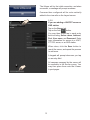
Vivotek iViewer is a monitoring app for iOS devices that allows you to view live video feeds from up to 72 network cameras, including those connected to VAST, ST7501, or VIVOTEK's NVR servers. You can easily add cameras to the app by entering their IP addresses and credentials, or by selecting them from a list of previously configured devices. iViewer also supports PTZ control for compatible cameras, as well as PiP (Picture in Picture) mode for viewing multiple camera feeds simultaneously.
Vivotek iViewer is a monitoring app for iOS devices that allows you to view live video feeds from up to 72 network cameras, including those connected to VAST, ST7501, or VIVOTEK's NVR servers. You can easily add cameras to the app by entering their IP addresses and credentials, or by selecting them from a list of previously configured devices. iViewer also supports PTZ control for compatible cameras, as well as PiP (Picture in Picture) mode for viewing multiple camera feeds simultaneously.


-
 1
1
-
 2
2
-
 3
3
-
 4
4
-
 5
5
-
 6
6
-
 7
7
-
 8
8
-
 9
9
-
 10
10
-
 11
11
-
 12
12
-
 13
13
-
 14
14
-
 15
15
-
 16
16
-
 17
17
-
 18
18
-
 19
19
-
 20
20


Vivotek iViewer is a monitoring app for iOS devices that allows you to view live video feeds from up to 72 network cameras, including those connected to VAST, ST7501, or VIVOTEK's NVR servers. You can easily add cameras to the app by entering their IP addresses and credentials, or by selecting them from a list of previously configured devices. iViewer also supports PTZ control for compatible cameras, as well as PiP (Picture in Picture) mode for viewing multiple camera feeds simultaneously.
Ask a question and I''ll find the answer in the document
Finding information in a document is now easier with AI
Related papers
Other documents
-
EverFocus NVR-4000/12T Datasheet
-
EverFocus Elite2 NVR8004X-20 Owner's manual
-
Geovision GV-Eye Installation guide
-
ACTi NVR 3 Corporate V3.0.12 Administrator Manual
-
Geovision GV-NVR SYSTEM LITE V2 User manual
-
-
-
FLIR DN104P2E4 Series User manual
-
Digimerge DN308P28 User manual
-