Kenmore 25370187000 Installation guide

Type
Installation guide
Installation Instructions
For A-Kit HDSD
Please read ALL instructions before installing. Two
people are recommended to install this product. If
a new electrical oudet is required, have the outlet
installed by a qualified electrician before installing
unit. See #5 in Preliminary Instructions following.
WINDOW SASH SEAL
SAFETYLOCKAND
2/4"LONGHEXHEADSCREW
Preliminary Instructions
TOPANGLE
Do the following before starting to install unit. FOAMt
See illustrations below. WASHERHEAD
1. Check window opening size - the mounting
parts furnished with this air conditioner are
made to install in a wooden sill double-hung
gindow. The standard parts are for a window
opening of 31" (711 nun) minimum to 42"
(1067 mm) maximum width. Open sash to a
minimum of 19" (483 ram). (FIG. 1)
2. Check condition of window - all wood parts
of window must be in good shape and able to
firmly hold the needed screws. If not, make
repairs before installing unit.
3. Check your stotan windows - ff your storm
window frame does not allow the clearance
required, correct by adding a piece of wood
as shown in FIG. 2, or by removing storm
window while room air conditioner is being
installed, qcontinued)
FIG. I _SASH
._ MIN.
STORMWINDOWFRAME
19"MIN.
1
OR OTHER OBSTRUCTION
FRAME
ASSEMBLY
(LEFT)
SIDE RETNNER
SEAL-BOTTOMRAILTO UNIT
FLATHEAD
BOLT
ASS_B_
BRACKET
_LL ANGLE
BRA_<ET
rl
FIG, 2
SASH
19=MIN.
1/2"MIN. 1 1/2"M_N._1
STORM WINDOW FRAME
OR OTHER OBSTRUCTION
T
BOARDTHICKNESS AS
REQUIRED,ALONG
ENTIRESTOOL.
FASTENWITH TWO
N/_LS ORSCREWS.
1 309000906 (9607)
4. CHECK FOR ANYTHING THAT COULD
BLOCK AIRFLOW - check area outside
of window for things such as shrubs,
trees, or awnings. Inside, be sure
furniture, drapes, or blinds will not
stop proper airflow.
5. Check the available electrical service -
power supply must be the same as that
shown on the unit serial nameplate. (See
Owner's Guide fDr serial plate location.)
Power cord is 48" long. Be sure you have an
outlet near. It is best to not use extension
cords!
All models have a 3-prong service plug to
provide proper service and safe positive
grounding. Do not change plug in any way.
Do not use an adapter plug. If your present
wall outlet does not match your plug, call a
qualified electrician to make the needed
change.
Avoid fire hazard or
rtX_a_tĀ¢
electric shock. Do not use an extension
cord or an adapter plug. Do not remove
any prong from the power cord.
GroundinĀ¢
Powersupply
cord with 3-prong
grounding plug
6. Carefully unpack air conditioner - remove
all packing material. Protect floor or carpet
from damage. Two people should be used to
move and install unit.
Tools Required
a large flat blade screwdriver
x/ #2 Phillips screwdriver
_] tape measure
"_ adjustable wrench or pliers
4 pencil
Hardware (in plastic bag)
Washer Head
Locking Screw
3/4" Long Hex-
Head Scow
Safety Lock
_ 1/2" Long
Screw and
Locknut
_@ 3/4" Long Flat
Head Bolt and
Locknut
?
Sill Angle
Bracket 2
Screws Top
Angle Side
Retainer
Top Angle &
Side Retainers
2
3
1
4 ea.
2 e2.
10
2
f
2
Window Mounting
Remove Chassis
STRAP/HANDLE NOTE: Do not use strap for lifting
unit. It is for sliding chassis WITHIN cabinet only (to
aid in cleaning, maintenance, etc.). Be CAREFUL of
sharp edges on coil fins.
1.
To slide chassis from the cabinet, ftrst remove
the two (2) screws on top of the cabinet, hold
the cabinet while pulling on the strap/handle
provided at the front of the unit. If unit does not
have a handle, slide chassis from cabinet by
pulling vertical (up-down) flange at the top of
the chassis air opening, with fingers of both
hands. At the same time, push with thumbs
against top front edge of sleeve.
E !Assemble Window
,F,Iler Panels
1. Place cabinet on floor, a bench, or a table.
2. Slide hi" section of window filler panel into side
retainer on the side of the cabinet (see Figures
2-3). Do both sides.
FIG. 2
PLASTIC WINDOW RLLER
FRAME PANEL
SIDE
2.
l.
2.
Before proceeding to STEP 2 add the two (2)
short seals to cover the holes where retaining
_ were.
Install Top Angle
and Side Bracket
Attach foam gasket to top angle above screws as
shown in FIG. 1.
Install top angle and side retainers to cabinet
as shown in FIG. 1, using a Phillips screw.
FIG. I
FIG.
AIRCONDmONER
CAB_ET
_qEW
9"SECT_fl
W_NDOW
RLLER
PANEL
3. Insert top and bottom legs of window filler
panel frame into channel in the top angle and
bottom rail. Do both sides.
4.
Insert washer head locking screws (2) into
holes in top leg of filler panel frame (see
Step 6). Do not totally tighten. Allow leg to
slide freely. Screws will be tightened after
Section 6.
318"Long SlottedRound
Head Screw
3
Place Cabinet in
Window
1. Open window and mark
center of window stool.
,
Install Support
;racket
Hold each support bracket flush against
outside of sill, and tight to bottom of cabinet
as shown below. Mark brackets at top level of
sill, and remove.
.
Place cabinet in window with bottom stool
angle firmly seated over window stool as
shown. Bring window down temporarily
behind top angle to hold cabinet in place.
STOOL /
_STOOL
3. Shift cabinet left or right as needed to line up
center of cabinet on center line marked on
stool.
4. Fasten cabinet to window stool with 2 screws
into holes. (You may wish to pre-drill pilot
boles.)
5. Add bottom rail seal over screws to window
stool.
3/4" LONG HEX-
HEAD SCREW
4
1/2" LONG SCREWS
LEFT
\ LOCKNUTS
t
SILL ANGLE
FLAT HEAD BOLT
IHT
2 EACH REQ'D FOR EACH
SUPPORT BRACKET
2. Assemble sill angle bracket to support brackets
at the marked position, as shown. Hand
tighten, but allow for any changes later.
3. Install support brackets (with sill ngle
brackets attached) to correct hole in bottom
of cabinet as shown.
4. Tighten all 6 bolts securely.
1/2"long screws
andIocknuts
1.
Extend Window Filler
Panels
Carefully raise window to expose filler panel
locking screws. Loosen screws so filler panels
slide easily.
I_lilnstall Chassis into
Cabinet and Install
Front to Unit
1. Lift chassis and carefully slide it into installed
cabinet.
2. _ Do not push on controls OR
finned coils.
3. Be sure chassis ksfirmly seated towards rear of
cabinet.
4. Refer to Owner's Guide for front installation.
2. Extend panels to fill window opening
completely. Tighten locking screws on too.
3. Close window behind top angle.
o
Install Window Lock
and Sash Seal
Trim sash seal to fit window width. Insert
into space between upper and lower sashes.
_IDOWSASH SEAL
2. Attach right angle safety lock as shown.
head screw
Thru-The-Wall Installation
NOTE: Consult local building codes prior to
installation, or a qualified carpenter.
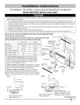
Carefully measure and cut an opening with the
following dimensions. See FIGS. 1 and 2.
Select Wall Location
WIDTH "X_' = 26-3/4" (67.9cm) plus twice the
thickness of flaming material used.
This air conditioner has a slide-out chassis, so it
can be installed through an outside wall up to 12"
thick. IMPORTANT: Side louvers must never be
blocked.
NOTE: All parts needed for Thru-The-Wall
Installation are provided, except a wood frame,
shims, and 10 wood screws (#10-1" long
minimum). Select a waR surface that:
1. does not support major structural loads such
as the frame construction at ends of windows,
and under truss-bearing points, etc.
2. does not have plumbing or wiring inside.
3. is near existing electrical outlets, or where
another outlet can be installed.
4. faces, and is not blocked to the area to be
cooled.
5. aUows unblocked airflow from rear sides and
end (outside) of installed air conditioner.
Wall
1. Prepare war in frame construction (including
brick and stucco veneer). Working from inside
the room, find war stud nearest the center of
area where air condiu'oner will be installed (by
sounding wall, or by magnetically finding
nails).
2. Cut or knock out a hole on each side of center
stud.
3. Measure between inside edges of every other
stud as shown in FIG. 1.
i
I
I
I
FIG. I
.
,
HEIGHT 'Y' = 18-7/8" (47.9 cm) plus twice the
thickness of framing material used.
Y
FIG. 2
Build a wooden sleeve with the INSIDE
dimensions of 26-3/4" (67.9 cm) in width
and 18-7/8" (47.9 cm) in height. Frame depth
should be the same as wall thickness. Fill in
the space fi'om the opening to the studs with
wood spacers, as shown.
Nail frame to spacers with front flush with
drywall.
-NAIL SPACERS TO
(8.6cm) -*.
6
NOTE: If wall thickness is 8-1/2" or more, add
aluminum flashing over bottom of frame opening
to assure no water can enter area between inner
and outer wall.
FIG. 2
ALUMINUM FLASHING
OVER BO'I-rOM OF FRAME
OVER
8-1/2'
OlrrIONAL: Support brackets may be used.
Installation brackets are recommended for walls
under 5" thick.
Refer to Step 4 of Window Mounting for
assembly of support brackets. A wooden strip
nailed to the outside wall should be used in
angle brackets.
Prepare and Install
m Cabinet
1. Slide chassis from cabinet. Refer back to Step 1
of Window Mounting.
2. Place cabinet into opening with bottom rail
resting firmly on bottom board of wooden
frame.
3. Position cabinet to achieve proper slope for
water removal. (See FIG. 1 below.)
FIG. I
TO
318"
3/4" PLUS
SEE PAPA 5
.
Support bracket
Wooden strip
Screw or nail cabinet to wooden frame using
shims if frame is oversized, to eliminate
distortion. Remember to maintain proper
slope as described in Step 3.
7
LEVEL
. Secure bottom raft to wood frame with two
large wood screws 1" (2.5 cm) long using the
two holes in the bottom of the channel resting
on frame. (See FIG. 2 following.)
7
6. Install chassis into cabinet by following all
steps in Step 8 of Window Mounting.
(continued)
OPTIONAL: Caulking and installation of trim on
interior wall may be done. You can buy wood
from your local lumber or hardware supply. On
the outside, caulk openings around top and sides
of cabinet, and all sides of wood sleeve to the
opening.
NOTE: See Step 7, Item 3 of Window Mounting
Instructions for bottom rail seal location.
Masonry Construction
1. Cut or build a wall opening in the masonry
wall similar to the frame construction (refer to
Step 2 of Thru-the-Wall Installation for a wall
thickness greater than 8-1/2').
2. Secure cabinet in place using masonry nails, or
the right masonry anchor screws. (Another
way to do this is to build an in-between frame
of 2x4's as shown in the Step 2 Prepare Wall
illustrations--- but make it double framed on
either side, and install between masonry wall
opening and cabinet. Frame must be securely
anchored to masonry wall opening.) This way
gives very good louver clearance on either side
of cabinet.
.
Install a lintel to support masonry wall above
cabinet. Existing holes in cabinet can be used
and/or additional holes can be drilled to fasten
cabinet at various positions, Be sure that side
louver clearance is in accordance with Step 1
above.
4. Install exterior cabinet support brackets as
shown in Step 2 of Thru-the-Wall Installation.
Caulk or flash if needed, to provide a weather-
tight seal around top and sides of cabinet.
5. To complete installation, apply wood trim
molding around room side projection of
cabinet.
8
  • Page 1 1
  • Page 2 2
  • Page 3 3
  • Page 4 4
  • Page 5 5
  • Page 6 6
  • Page 7 7
  • Page 8 8
  • Page 9 9
  • Page 10 10
  • Page 11 11
  • Page 12 12
  • Page 13 13
  • Page 14 14
  • Page 15 15
  • Page 16 16
  • Page 17 17
  • Page 18 18
  • Page 19 19
  • Page 20 20
  • Page 21 21
  • Page 22 22
  • Page 23 23
  • Page 24 24

Kenmore 25370187000 Installation guide

Type
Installation guide

Ask a question and I''ll find the answer in the document

Finding information in a document is now easier with AI