Hitachi 51F59 Owner's manual

Category
LCD TVs
Type
Owner's manual

This manual is also suitable for

HiTACHi
inspire the Ne×
PROJECTION COLOR TELEVISION
Operating Guide for 51F59, 51F59A
57F59A, 57F59J
65F59, 65F59A, 65F59J.
IMPORTANT SAFETY INSTRUCTIONS ....................................................................................... 2-3
FIRST TIME USE ....................................................................................................................... 4-17
TH E REMOTE CONTROL ..................................................................................... 18-31
ON-SCREEN DISPLAY ..................................................................................................... 32-60
USEFUL INFORMATION ................................................................................................ 61-71
END USER LICENSE AGREEMENT FOR HITACHI DTV SOFTWARE ................................... 71
INDEX ........................................................................................................................................... 72
As an Energy Star_ Partner,
Hitachi, Ltd. has determined
that this product meets the
Energy StaF_guidelines for
energy efficiency
SAFETY POINTS YOU SHOULD KNOW ABOUT
YOUR HITACHI TELEVISION
Our reputation has been built on the quality,
performance, and ease of service of HITACHI
televisions.
Safety is also foremost in our minds in the design of
these units. To help you operate these products
properly, this section illustrates safety tips which will be
of benefit to you. Please read it carefully and apply the
knowledge you obtain from it to the proper operation of
your HITACHI television.
Please fill out your warranty card and mail it to
HITACHI. This will enable HITACHI to notify you
promptly in the improbable event that a safety problem
should be discovered in your product model.
Follow all warnings and instructions marked on
this television.
CAUTION I
CAUTION: TO REDUCE THE RISK OF ELECTRIC SHOCK,
DO NOT REMOVE COVER (OR BACK).
NO USER SERVICEABLE PARTS INSIDE.
REFER SERVICING TO QUALIFIED SERVICE PERSONNEL.
The lightning flash with arrowhead symbol,
within an equilateral triangle, is intended to
alert the user to the presence of
uninsulated "dangerous voltage" within the
product's enclosure that may be of a sufficient
magnitude to constitute a risk of electric shock to a
person.
,_The exclamation point within an equilateral
triangle, is intended to alert the user to the
presence of important operating and
maintenance (servicing) instructions in the
literature accompanying the appliance.
READ BEFORE OPERATING EQUIPMENT
Follow all warnings and instructions marked on this
television.
1. Read these instructions.
2. Keep these instructions.
3. Heed all warnings.
4. Follow all instructions.
5. Do not use this apparatus near water.
6. Clean only with a dry cloth.
7. Do not block any ventilation openings. Install in
accordance with the manufacturer's instructions.
8. Do not install near any heat sources such as
radiators, heat registers, stoves, or other apparatus
(including amplifiers) that produce heat.
9. Do not defeat the safety purpose of the polarized or
grounding-type plug. A polarized plug has two
blades with one wider than the other. A grounding
type plug has two blades and a third grounding
prong. The wide blade or the third prong are
provided for your safety. If the provided plug does
not fit into your outlet, consult an electrician for
replacement of the obsolete outlet.
10. Protect the power cord from being walked on or
pinched particularly at plugs, convenience
receptacles, and the point where they exit from the
apparatus.
11. Only use the attachments/accessories specified by
the manufacturer.
12. Use only with the cart, stand, tripod,
bracket, or table specified by the
I manufacturer, or sold with the
apparatus. When a cart is used, use
caution when moving the cart/apparatus
combination to avoid injury from tip-over.
13. Unplug this apparatus during lightning storms or
when unused for long periods of time.
14. Refer all servicing to qualified service personnel.
Servicing is required when the apparatus has been
damaged in any way, such as power-supply cord or
plug is damaged, liquid has been spilled or objects
have fallen into apparatus, the apparatus has been
exposed to rain or moisture, does not operate
normally, or has been dropped.
15. Televisions are designed to comply with the
recommended safety standards for tilt and stability.
Do not apply excessive pulling force to the front, or
top, of the cabinet which could cause the product
to overturn resulting in product damage and/or
personal injury.
16. Follow instructions for wall, shelf or ceiling
mounting as recommended by the manufacturer.
17. An outdoor antenna should not be located in the
vicinity of overhead power lines or other electrical
circuits.
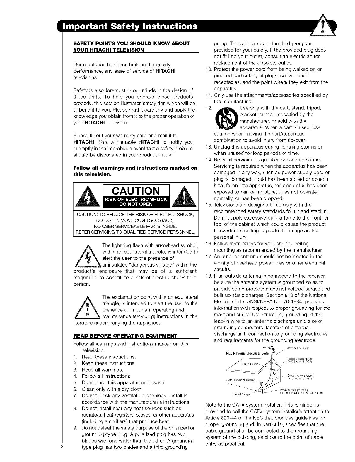
18. If an outside antenna is connected to the receiver
be sure the antenna system is grounded so as to
provide some protection against voltage surges and
built up static charges. Section 810 of the National
Electric Code, ANSl/NFPA No. 70-1984, provides
information with respect to proper grounding for the
mast and supporting structure, grounding of the
lead-in wire to an antenna discharge unit, size of
grounding connectors, location of antenna-
discharge unit, connection to grounding electrodes
and requirements for the grounding electrode.
C_-'_r=_'-'Ode_'_" / Anten_,ale_d-ill wire
NEC National Electrical _"
_/ ntelllla discilalg8 {_nit
(NECSection 810-20}
e__ Gt0undi_,g conductors
(NECSectton 810 21_
_leclricservice equpner_t. , - /
_ower service grounding
Gr0_d clamps _ "_ ...... elecirode system (NEe Art 250 Part 14)
Note to the CATV system installer: This reminder is
provided to call the CATV system installer's attention to
Article 820-44 of the NEC that provides guidelines for
proper grounding and, in particular, specifies that the
cable ground shall be connected to the grounding
system of the building, as close to the point of cable
entry as practical.
Power source
This television is designed to operate on 120 volts
60 Hz, ac current. Insert the power cord into a 120 volt
60 Hz outlet.The power cord is used as the disconnect
device and shall remain readily operable.
To prevent electric shock, do not use the television's
(polarized) plug with an extension cord, receptacle, or
other outlet unless the blades and ground terminal can
be fully inserted to prevent blade exposure.
Never connect the television to 50 Hz, direct current, or
anything other than the specified voltage.
Caution
Never remove the back cover of the
television as this can expose you to very
high voltages and other hazards. If the
television does not operate properly,
unplug the television and call your authorized dealer or
service center.
Caution
Adjust only those controls that are covered in the
instructions, as improper changes or modifications not
expressly approved by HITACHI could void the user's
warranty.
Warning
To reduce the risk of fire or electric shock, do not
expose this apparatus to rain or moisture.
The television should not be exposed to dripping or
splashing and objects filled with liquids, such as
vases, should not be placed on the television.
Warning
Do not place any objects on the top of the television
which may fall or cause a child to climb to retrieve
the objects.
Projection TV's are heavy and can mark or damage
floor surfaces (especially wood flooring) if moved
improperly. Do not slide or force TV into position.
Always roll TV allowing casters at bottom of unit to
help steer and position the TV.
FCC Information
This device complies with part15 of the FFC Rules.
Operation is subject to the following two conditions
(1) This decide may not cause harmful interference,
and (2) This decide must accept any interference
received, including interference that may cause
undesired operation.
Modifications
The FCC requires the user to be notified that any
changes or modifications made to this device that are
not expressly approved by Hitachi America, Ltd. Home
Electronics Division may void the user's authority to
operate the equipment.
Note
This television receiver will display television closed
captioning, ([_ or[_), in accordance with paragraph
15.119 and 15.122 of the FCC rules.
Public viewing of copyrighted material
Public viewing of programs broadcast by TV stations
and cable companies, as well as programs from other
sources, may require prior authorization from the
broadcaster or owner of the video program material.
This product incorporates copyright protection
technology that is protected by U.S. patents and other
intellectual property rights. Use of this copyright
protection technology must be authorized by
Macrovision Corporation, and is intended for home and
other limited consumer uses only unless otherwise
authorized by Macrovision. Reverse engineering or
disassembly is prohibited.
Note
This digital television is capable of receiving analog
basic, digital basic cable television programming by
direct connection to a cable system providing such
programming. Certain advanced and interactive
digital cable services such as video-on-demand, a cable
operator's enhanced program guide and data-enhanced
television services may require the use of a set-top box.
For more information call your local cable company.
Note
There are no user serviceable parts inside the
television.
Model and serial numbers are indicated on back side
of the television.
Prevention of screen burn
This Wide Screen TV is designed to display wide
screen pictures. Images should be viewed mostly in
wide screen format or zoomed to fit the screen with
moving pictures. Use of side panels, top and bottom
panels of standard picture formats should only be 15%
of your total viewing time to prevent uneven aging of
the phosphors. Phosphors in the lighted area of the
picture will age more rapidly than the gray areas.
Continuous on-screen displays such as video games,
stock market quotations, computer generated graphics,
and other fixed (non-moving) patterns can cause
permanent damage to television receivers. Such
"SCREEN BURNS" constitute misuse and are NOT
COVERED by your HITACHI Factory Warranty.
Lead Notice
This product contains lead. Dispose of this product in
accordance with applicable environmental laws. For
product recycling and disposal information, contact
your local government agency or the Electronic
Industries Alliance at www.eiae.org (in the US) or the
Electronic Product Stewardship Canada at
www.epsc.ca (in Canada).
FOR MORE INFORMATION, CALL 1-800-HITACHI.
Check to make sure you have the following accessories before disposing of the packing material,
O Remote Control _ Two "AA" size,
1.5V batteries
: , j i
iVOLi ic_i
MUTE L_T CH
f_
_) "Z" Allen Key
(65" Models Only)
O Remote Control Unit CLU-4361S (Part No. HL02291),
Two "AA" size, 1.5V batteries (For Remote Control Unit).
"Z" Allen Key (Part No. 61010122). Provided only when Allen Screws are used.
REMOTE CONTROL BATTERY INSTALLATION AND REPLACEMENT
1. Open the battery compartment cover of the remote control
by pulling back the TAB and lifting up to remove the cover.
2. Insert two new "AA" size batteries into the remote control.
When replacing old batteries, push them back towards
the springs and lift out.
3. Match the batteries to the (+) and (-) marks in the battery
compartment.
4. insert the (-) side, into the battery compartment, the slide
the battery inwards and insert the second battery. Do not
force the battery into the battery compartment.
5. Replace the battery compartment cover.
Bottom View (Remote Control)
Pull up tab to remove back cover.
ANTENNA
Unless your TV is connected to a cable TV system or to a centralized antenna system, a good outdoor TV antenna
is recommended for best performance. However, if you are located in an exceptionally good signal area that is free
from interference and multiple image ghosts, an indoor antenna may be sufficient.
LOCATION
Select an area where sunlight or bright indoor illumination will not fall directly on the picture screen. Also, be sure
that the location selected allows a free flow of air to and from the perforated back cover of the set. To avoid
cabinet warping, cabinet color changes, and increased chance of set failure, do not place the TV where
temperatures can become excessively hot, for example, in direct sunlight or near a heating appliance, etc.
VIEWING
The major benefit of the HITACHI Projection Television
is its large viewing screen. To see this large screen at its
best, test various locations in the room to find the
optimum spot for viewing.
The best picture is seen by sitting directly in front of the
TV and about 10 to 18 feet from the screen. Picture
brightness decreases as the viewer moves to the left
and right of the receiver.
During daylight hours, reflections from outside light may
appear on the screen. If so, drapes or screens can be
used to reduce the reflection or the TV can be located in
a different section of the room.
If the TV's audio output will be connected to a Hi-Fi
system's external speakers, the best audio performance
will be obtained by placing the speakers equidistant
from each side of the receiver cabinet and as close as
possible to the height of the picture screen center. For
best stereo separation, place the external speakers at
least four feet from the side of the TV, place the
surround speakers to the side or behind the viewing
area. Differences in room sizes and acoustical
environments will require some experimentation with
speaker placement for best performance.
10' 1_5' 20'
4" Minimum
4" Minimum
+i_!_!lil!li!i!+i!+i!+i!+i!+i!+i!+i!+i!+i!+i!+i!+!_!+!+!!i!+!i!;i!i+_ilililililililililililililililililili_i¸ii¸ii¸ii¸ii++i
iiiilili%!!!i!!i!!!!!i!iiiilililiiiiiiiiiii!ii!ii!ii!ii!ii!ii!ii!iiiii
iiiiiiiii!i!!!!!i!!!!!i!!i!!i!i!i!i!i!!ii!!ii!!iiiiiiiiili++Diiiiiiill
Most video/audio connections between components can be made with shielded video and audio cables that have
phono connectors. For best performance, video cables should use 75-Ohm coaxial shielded wire. Cables can be
purchased from most stores that sell audio/video products. Below are illustrations and names of common
connectors. Before purchasing any cables, be sure of the output and input connector types required by the
various components and the length of each cable.
300.Ohm Twin Lead Cable
This outdoor antenna cable must be connected to an
antenna adapter (300-Ohm to 75-Ohm).
Phone Cable
Used on all standard video and audio cables which
connect to inputs and outputs located on the
television's rear jack panel and front control panel.
"F" Type 75-Ohm Coaxial Antenna Cable
For connecting RF signals (antenna or cable TV) to the
antenna jack on the television.
S-Video (Super Video) Cable
This connector is used on camcorders, VCRs and laser-
disc players with an S-Video feature in place of the
standard video cable to produce a high quality picture.
Optical Cable
This cable is used to connect to an audio amplifier with
an Optical Audio In jack. Use this came for the best
sound quality.
HDMI Cable
This cable is used to connect your external devices
such as Set-Top-Boxes or DVD players equipped with
an HDMI output connection to the TV's HDMI input.
®
ANTENNA CONNECTIONS TO REAR JACK PANEL
(75-Ohm) antenna/CATV (Cable TV)
When using a 75-Ohm coaxial cable system, connect
Antenna or CATM coaxial came to the AIR/CABLE
(75-Ohm) terminal.
VHF (300-Ohm) antenna/UHF antenna
When using a 300-Ohm twin lead from an outdoor
antenna, connect the VHF or UHF antenna leads to
screws of the VHF or UHF adapter. Plug the adapter
into the AIR/CABLE terminal on the T_Z
When both VHF and UHF antennas are
connected
Attach an optional antenna cable mixer to the TV
AIR/CABLE terminal, and connect the cables to the
antenna mixer. Consult your dealer or service store
for the antenna mixer.
____._, To outdoor antenna
To outdoorVHF
or UHF antenna
From UHF antenna (_
q,
Antenna Mixer
From outdoor
antenna or
CATV System
In addition to controlling all of the functions on your HITACHI Projection TV, the new remote control is designed to
operate different types of devices, such as, DVD Players, CBL (Cable Boxes), set-top-boxes, satellite receivers,
and VCRs. The remote control must be programmed to control the chosen device. Please see page 18-31 for a
complete description of all features and programming of the Remote Control.
POWER BUTTON
(TV, CBL, VCR, DVD, SAT)
Turns the selected device on
and off.
iNPUTS BUTTON
Accesses the INPUTS menu
system.
ASPECT BUTTON
Changes the aspect ratio while
watching TV.
MENU BUTTON
(CBL, DVD, SAT, TV}
Accesses the OSD menu
system.
CURSOR/SELECT BUTTONS
(TV, DVD, CBL, SAT)
The CURSOR buttons are used
to navigate the cursor through
the OSD and INPUTS menu
systems, and the SELECT
button is used to
Select/Activate the highlighted
menu item.
VOLUME BUTTONS
Adjusts the audio level of your
TV.
MUTE BUTTON (TV}
Reduces the audio level to 50%
if pressed once, and to
complete mute if pressed twice.
Press it a third time to restore
audio level.
SOURCE ACCESS BUTTONS
(TV, DVD, VCR, CBL, SAT}
Changes the mode of the
Universal Remote Control to
control the device selected.
(Tv}
Select picture mode settings
between DAY and NIGHT mode.
BUTTON (TV}
Press to show and change the
Picture-in-Picture mode.
BUTTON
(TV, CBL, SAT}
Exits out of the OSD or INPUTS
menu systems if their menu is
displayed.
-INFO BUTTON
(TV, CBL, SAT}
Displays various information on
the screen.
-GUIDE BUTTON
(SAT/STB, CBL}
Accesses the program guide of
other devices.
LAST CHANNEL (LC} BUTTON
(TV, CBL, SAT}
Switches between the current
and last channel viewed.
CHANNEL BUTTONS
(TV, CBL, SAT, VCR}
Changes the channel.
(TV, DVD, CBL, SAT, VCR}
Used to manually enter the TV
channel, and used for numeric
entry when navigating through
the OSD menu system.
(-) BUTTON (TV, SAT)
The (-) button is used when the
remote is in Set-Top-Box (STB)
mode or when the "iV uses a
digital input.
RECORD BUTTON (VCR)
Press twice (2 times) to record
programs.
CHANNEL
(FAV CH) button (TV}
Press to enter/access Favorite
Channel (FAV) mode.
DVD/VCR CONTROL
BUTTONS (DVD, VCR)
Controls the precode functions
of your VCR and DVD.
PAUSE BUTTON
(TV, VCR, DVD}
Press to show and change the
Freeze mode of the TV or pause
other devices.
LEGEND
"rv - Television
CBL - Cable Box
STB - Set-Top-Box
VCR - Video Cassette Recorder/Player
DVD - Digital Video Disc Player
SAT - Satellite Receiver
IN_JT _ @
i
FOCLI8 _ '_ _ T CH & INL_II" MENU POWER
0 0 0 0
_o_R0
]
0
0
O
0
0
MENU/SELECT button
This button allows you to enter the MENU, making
it possible to set TV features to your preference
without using the remote. This button also serves
as the SELECT button when in MENU mode.
INPUT/EXIT button
Press this button to display the input menu,
CABLE, AIR, INPUT: 1,2, 3, 4 and 5. This button
also serves as the EXIT button when in MENU
mode.
CHANNEL selector
Press these buttons until the desired channel
appears in the top right corner of the TV screen.
These buttons also serve as the cursor down (Y)
and up (&) buttons when in MENU mode.
O
O
POWER button/POWER LED
Press this button to turn the TV on or off. This LED
light is on during normal operation. At initial TV turn
on, the TV cannot receive any button or Remote
Control signals for approximately five seconds
while the internal programming is loading. This is a
normal default operation of this television and is an
energy saving feature.
VOLUME level
Press these buttons for your desired sound level. O
The volume level will be displayed on the TV
screen. These buttons also serve as the cursor left
(_1) and right (1_) buttons when in MENU mode.
When the TV power is turned OFF at a volume level
31 or greater, the volume level will default to 30
when the TV is turned ON. However, if it is set to a
level 30 or less, the volume level will be at the level
it was set when the TV is turned ON. Q
MAGIC FOCUS button
Use this button to automatically adjust your picture
quality to optimum performance (see page 53).
FRONT INPUT JACKS (INPUT 5)
Use these audio/video jacks for a quick hook-up
from a camcorder or VCR to instantly view your
favorite show or new recording. Press the INPUT
button and select INPUT 5. If you have mono
sound, insert the audio cable into the left audio
jack.
IR RECEIVER Sensor
Point the remote control at this area when selecting
channels, adjusting volume, etc.
ThefrontpaneljacksareprovidedasaconveniencetoallowyoutoeasilyconnectacamcorderorVCRasshown
inthefollowingexamples:
S-INPUT
(Optional,seenote
\
S-VIDEO _DEO AUDIO
,-. @ ®®
i
S-VHS V UT
Back of VCR
J ..d
, =:z ©I_ j
i
INPUTs @
VIDEO ,_BIO
L/MONO _
©®
l INPUT
OUTPUT
S-VHS UT
S-VHS Video camera
AIR/ CABLE
_0
O AIR/CABLE Input
A 75-Ohm RF Antenna or CATV (Cable
TV) input.
t_ Audio/Video INPUTS t, 2, 3 and 4
By using the INPUTS button, CURSOR buttons
and SELECT button of the remote control you can
select each video source. Use the audio and video
inputs to connect external devices, such as VCRs,
camcordere, laserdisc players, DVD players etc. (if
you have mono sound, insert the audio cable into
the left audio jack.)
0 Audio Out
These jacks provide fixed or variable audio
signals which are used for recording.
O
O
S-Video INPUTS t and 2
INPUTS I and 2 provide S-Video (Super Video)
jacks for connecting equipment with S-Video
output capability.
Component: Y-PBPn INPUTS
INPUTS 3 and 4 provide Y-PBPR jacks for
connecting equipment with this capability, such as
a DVD player or Set Top Box. You may use
composite video signal for both inputs.
0
ta_
d_x_
mDo;_
_loOBe
Ut te_
)o_neo_
HDMI1 (High Definition Multimedia
Interface) (INPUT 1) __T_
ABOUT HDMI - HDMI is the ..................................
next-generation all digital interface for consumer
electronics. HDMI enables the secure distribution
of high-definition video and multi-channel audio in
a single cable. Because digital television (DTV)
signals remain in digital format, HDMI assures that
pristine high-definition images retain the highest
video quality from the source all the way to your
tetevision screen.
Use the HDMI input for your external devices such
as Set-Top-Boxes or DVD players equipped with an
HDMI output connection.
HDMI, the HDMI logo and High-Definition
Multimedia Interface are trademarks or registered
trademarks of HDMI Licensing LLC.
10
¢
O---
AIR/ CABLE
--0
O Optical Out (Digital Audio)
This jack provides Digital Audio Output for
your audio device that is Dolby® Digital
compatible, such as an audio amplifier.
Manufactured under license from Dolby
Laboratories. "DOLBY" and the DOUBLE-D
symbol are trademarks of Dolby Laboratories,
0
0
Upgrade Card
This card slot is for future software upgrades.
Hitachi will notify you if a software upgrade is
required for your TV. In order to receive written
notification, please complete and return your
warranty card.
TV AS CENTER (INPUTS 1-4)
These jacks are for stereo amplifiers with center
signal output capability. This feature allows the TV
speakers to be used as a center speaker. The TV
must be set as a center channel by selecting TV
AS CENTER on the Internal Speakers Settings of
the Audio Menu (see page 38).
11
TIPS ON REAR PANEL CONNECTIONS
S-VIDEO, Y-PBPR and HDMI
connections are provided for
high performance laserdisc
players, VCRs etc. that have
this feature. Use these
connections in place of the
standard video connection if
your device has this feature.
If your device has only one
audio output (mono sound),
connect it to the left audio
jack on the television.
Refer to the operating guide of
your other electronic equipment
for additional information on
connecting your hook-up
cables.
An AUDIO system can be used
by connecting the AUDIO TO HI-FI
output of the TV. This can be
use when you like to control the
volume output by changing the
volume of the TV.
Outside Antenna
or Cable
You may use VIDEO or
S-VIDEO inputs to connect to
INPUT 1, INPUT 2 or INPUT 5,
but only one of these may be
used at a time.
i
AIR/ CABLE
}@
ii iii!ii!i ii!ii
OUTPUT _} OUTPUT
SVIDEOV L Y PB/G PR/Q_ L R
@oo _oooo
Connect only one component
_VCR, DVD player, camcorder,
etc.) to each input jack.
AUDIO AMP Laserdisc player, VCR, VCR #1 DVD Player
External
Digital
Component
with HDMI
output
capability
To an
amplifier/
receiver with
optical input
capability.
COMPONENT: Y-PBPR (INPUT 3 and INPUT 4)
connections are provided for high performance
components, such as DVD players and set-top-
boxes. Use these connections in place of the
standard video connection if your device has this
feature. INPUT 3 and INPUT 4 accepts both
composite and component video signals.
When using an I-tDMI input from a Set-Top-Box, it
is recommended that a 1080i or 720p input signal
is used.
Your component outputs may be labeled Y, B-Y,
and R-Y. In this case, connect the components
B-Y output to the TV's PB input and the
components R-Y output to the TV's PR input.
Your component outputs may be labeled Y-CBCR.
In this case, connect the components CB output to
the TV's PBinput and the components CRoutput to
the TV's PRinput.
12
You may use composite and component video
signals for INPUT 3 and INPUT 4.
It may be necessary to adjust TINT to obtain
optimum picture quality when using the Y-PaPa
inputs (see page 34).
|_NOTJ:
_ $}Qt'J,_J
_Z_ DV'
D;IVICle(
Mtchthenumbesbeowtothedgramfor /
speaker placement. C AU [3 N
O The television's internal speakers will act as _ _
center speaker (select AUDIO - INTERNAL
SPEAKERS - TV AS CENTER).
I_ These FRONT left and right speakers are --J/ _ /
connected to the FRONT output of a / @_ _ _
separate audio amplifier. !,:oV_@
t_ These REAR left and right speakers are _ _ 'i/
connected to the Rear output of a separate
audio amplifier. _:_!, _?_ _ _
0 This subwoofer is connected to the LFE/SUB
Out output of a separate audio amplifier. ......................... ::r: :
RCA Optical
Cable Cable
L R CENTER OPTICAL
FRONT OUT IN
OITL OUT
Ste_o System Amplifier
REAR OUT LF_SUB
StereoSystemAm_#ie_
or DVDPlayel
13
TheexactarrangementyouusetoconnecttheVCR,camcorder,laserdiscplayer,DVDplayer,orHDTVSetTop
BoxtoyourTVsetisdependentonthemodelandfeaturesofeachcomponent.Checktheowner'smanualof
eachcomponentforthelocationofvideoandaudioinputsandoutputs.
Thefollowingconnectiondiagramsareoffered as suggestions. However, you may need to modify them to
accommodate your particular assortment of components and features. For best performance, video and audio
cables should be made from coaxial shielded wire.
BEFORE OPERATING
EXTERNAL VIDEO SOURCE
Connect an external source to the INPUT terminal, then
press the INPUTS button to show the INPUTS menu.
Use the CURSOR PAD to select the CABLE, AIR or
INPUT of your choice. Then press the SELECT button
to confirm your choice (see page 21).
[S_Ot
_set
_ Wde
)EO_#
_n_ec;
fill _ol
CONNECTING A COMPOSITE VIDEO
AND A MONAURAL AUDIO SOURCE
TO INPUT1 - INPUT5
Connect the cable from the VIDEO OUT of the VCR
or the laserdisc player to the INPUT (VIDEO) jack,
as shown on the TV to the right.
Connect the cable from the AUDIO OUT of the
VCR or the laserdisc player to the INPUT
(MONO)tL(AUDIO) iack.
Press the INPUTS button, then select INPUT 4
from the INPUTS menu to view the program from
the VCR or the laserdise player. The VIDEO OSD
label disappears automatically after approximately
four seconds.
Select CABLE/AIR from the INPUTS menu to return
to the last channel tuned.
VCR
14
CONNECTING A COMPOSITE VIDEO AND A
STEREO AUDIO SOURCE TO INPUT1 - INPUT5 ]AUT IN
Connect the cable from the VIDEO OUT of the VCR
or the laserdisc player to the INPUT (VIDEO) jack,
as shown on the TV to the right.
Connect the cable from the AUDIO OUT R of the
VCR or the laserdisc player to the INPUT
(AUDIO/R) jack.
Connect the cable from the AUDIO OUT L of the VCR
or the laserdisc player to the INPUT (AUDIO/L)jack.
Press the INPUTS button, then select INPUT 2
from the INPUTS menu to view the program from
the VCR or laserdisc player. The VIDEO OSD label
disappears automatically after approximately four
seconds.
.... J
5. Select CABLE/AIR from the INPUTS menu to return
to the last channel tuned.
VCR
CONNECTING AN S-VIDEO
SOURCE TO INPUT 1_ 2 AND 5
1. Connect the cable from the S-VIDEO OUT of the
VCR or the laserdisc player to the INPUT (S-VIDEO)
jack, as shown on the TV to the right.
2. Connect the cable from the AUDIO OUT R of the
VCR or the laserdisc player to the INPUT
(AUDIO/R) jack.
3. Connect the cable from the AUDIO OUT L of the VCR
or the laserdisc player to the INPUT (AUDIO/L) jack.
Press the INPUTS button, then select INPUT 2
from the INPUTS menu to view the program from
the VCR or laserdisc player. The VIDEO OSD label
disappears automatically after approximately four
seconds.
5. Select CABLE/AIR from the INPUTS menu to return
to the last channel tuned.
__.J
Qoo@
R OUTPUT V S-VDEO
VCR
15
CONNECTING A COMPONENT SOURCE WITH
HDMI OR DVI CAPABILITY TO INPUT 1
Connect the HDMI or DVl to HDMI connection
cable from the output of the HDTV set top box or
DVD player to the HDMI input as shown on the TV
to the right. When using a component with DVl
output, you also have to connect the AUD}O (bUT
(R/L) of the component to the AUDIO IN (R/L) of
INPUT 1.
Press the INPUTS button, then select INPUT 1
from the INPUTS menu to view the program from
the HDTV set top box or DVD player. The VIDEO
OSD label disappears automatically after
approximately four seconds.
Select CABLE/AIR from the INPUTS menu to return
to the last channel tuned.
HDMI HDMI
DVI HOMI
CAUTION
DVDPlaye_orRDTVSTB
I°
R L V
: OUTPUT
DVDPlayeror HDTVSTB
16
CONNECTING A COMPONENT AND AN AUDIO
SOURCE TO INPUT 3 OR 4: Y-PBPR.
Connect the cable from the Y OUT of the
Laserdisc/DVD player or HDTV set top box to the
INPUT (Y) jack, as shown on the TV to the right.
Connect the cable from the CB/PB OUT or B-Y OUT
of the Laserdisc/DVD player or HDTV set top box
to the INPUT (PB) jack.
Connect the cable from the CR/PR OUT or R-Y OUT
of the laserdisc/DVD player or HDTV set top box to
the INPUT (PR) jack.
Connect the cable from the AUDIO ©UT R of the
Laserdisc/DVD player or HDTV set top box to the
INPUT (AUDIO/R) jack.
Connect the cable from the AUDIO OUT L of the
Laserdisc/DVD player or HDTV set top box to the
INPUT (AUDIO/L) jack.
Press the the INPUTS button, then select INPUT 3
from the INPUTS menu to view the program from
the Laserdisc/DVD player or HDTV set top box. The
VIDEO OSD label disappears automatically after
approximately four seconds.
Select CABLE/AIR from the INPUTS menu to return
to the last channel tuned.
@@@@@
R L PR PB Y
OUTPUT
DVDHayer
17
}nadditiontocontrollinga_lthefunctionsonyour
HITACHI Projection TV, the new remote control is
designed to operate different types of VCRs, CATV
(Cable TV) converters, set-top-boxes, satellite receivers
(SAT) and DVD players with one touch. Basic operation
keys are grouped together in one area.
To operate your TV, point the remote control at the
screen of the TV and press the TV button. The remote
will now control your television.
To operate your VCR, point the remote at the remote
sensor of the VCR and press the VCR button. The
remote will now control your VCR (see page 31 for
instructions on how to program the remote to control
your VCR).
To operate your cable box, point the remote at the
remote sensor of the cable box and press the CABLE
(CBL) button. The remote will now control your cable
box (see page 28 for instructions on how to program
the remote to control your cable box).
To operate your set-top-box or satellite receiver, point
the remote at the remote sensor of the set-top-box or
satellite receiver and press the SAT button. The remote
will now control your set-top-box or satel}ite receiver, if
you have a satellite receiver, use this button to program
your satellite receiver (see page 29 for instructions on
how to program the remote to control your SAT).
To operate your DVD player, point the remote at the
remote sensor of the DVD player and press the DVD
button. The remote will now control your DVD player
(see page 30 for instruction on how to program the
remote to control your DVD player).
VCR CBL S
iNPUTS ASPECT PiP DAY/
MENU EXiT
© ©
[NFO GUIDE
iAi
i i
ivo,i ' c.
MUTE i '_'
O i,T_ , .
LASTCH
©
\'S
S \" j
\8/¸
,/ _, ,/_'\. !_FAV_\
\ HITAc. /
18
INFO _' GUIDE
LASTCH
-0
0
e
0
POWER button
Press this button to turn the TV set on or off when
the remote is in TV mode. (See page 20 for
instructions on how to set the remote control to TV
mode.)
MODE buttons
These buttons allow the remote to control your TV,
VCR, DVD, Cable box/Satellite box depending on
which button is pressed.
PAUSE button
Press the PAUSE button to freeze the picture.
Press the EXIT button to return the picture to
motion. Press the PAUSE button repeatedly to
cycle through the three different freeze modes (see
page 24).
iiiiiiiiiiiiiiiiiiiiiiiiiiiiiiiiiiii!i Freeze
iiiiiiiiiiiiiiiiiiii..................iiiiiiiiiiiiiiiiiiiiiiii!iii!i!ii!iiiillI Froeze
_ii !_!i_i_i_i_i_i_i_i_ Freeze
O
DAY/NIGHT button
Press this button to toggle between Day and Night
picture mode settings. Select DAY for day time
viewing with more brightness and contrast to
compete with room light. Select NIGHT for night
time viewing with less brightness and contrast for a
more detailed picture (see page 34 for settings
changes).
19
20
O
ASPECT button
Press this button to quickly change the picture format ASPECT ratio. Depending on the input signal format
received, the picture format ratio allows you to adjust the images through the following options.
4:3 STANDARD
Use this aspect mode to display conventional (4:3)
images. Side panels (gray areas) are placed to the
left and right of the image to preserve the original
aspect ratio of the source. Note: Use this mode for
only 15% of your total viewing time to prevent
uneven aging of the phosphors. Phosphors in the
lighted area of the picture will age more rapidly
than the gray areas.
4:3 EXPANDED
Use this aspect mode to display conventional (4:3)
sources by linearly increasing image expansion
from the center towards the edges of the display
area in order to fill it.
4:3 ZOOMt/ZOOM2
Use these aspect modes to zoom in on
conventional (4:3) sources.
16:9 STANDARD
Use this aspect mode to display 16:9 sources like
HDTV and DVD's preserving the original 16:9
aspect ratio.
16:9 ZOOM
Use this aspect to Zoom-in once while in 16:9
aspect.
Antenna-Analog CH
S-Video/Video Input
(Auto Aspect: Off)
HDMI-480i/480p Input
(Auto Aspect: Off)
Component-480i/480p
Input (Auto Aspect: Off)
4:3 INPUT 4:3 STANDARD 4:3 EXPANDED 4;3 ZOOM1
l !
16:9 ZOOM 16:9 STANDARD 4:3 ZOOM2
Antenna-Digital CH (4:3)
S-Video/Video 4:3 Letter
Input (Auto Aspect: On)
HDMI-480i/480p 4:3/
Letter Input (Auto Aspect: On)
Component-480i/480p 4:3
Letter Input
(Auto Aspect: On)
4:3 INPUT
m
4:3 STANDARD 4:3 EXPANDED
| !
4:3ZOOM2 4:3ZOOM1
S-Video/Video 16:9 input
(Auto Aspect: On)
HDM|-480i/480p 16:9 Input
(Auto Aspect: On)
Component-480i/480p
16:9 Input
(Auto Aspect: On)
16:9 INPUT
I
16:9 STANDARD 16;9 ZOOM
Antenna-Digital CH (16:9)
HDMI-720p/1080i (
Component-720p/1080i
(16:9)Input
16:9 INPUT
16:9 STANDARD 16:9 ZOOM 4:3 EXPANDED
  • Page 1 1
  • Page 2 2
  • Page 3 3
  • Page 4 4
  • Page 5 5
  • Page 6 6
  • Page 7 7
  • Page 8 8
  • Page 9 9
  • Page 10 10
  • Page 11 11
  • Page 12 12
  • Page 13 13
  • Page 14 14
  • Page 15 15
  • Page 16 16
  • Page 17 17
  • Page 18 18
  • Page 19 19
  • Page 20 20
  • Page 21 21
  • Page 22 22
  • Page 23 23
  • Page 24 24
  • Page 25 25
  • Page 26 26
  • Page 27 27
  • Page 28 28
  • Page 29 29
  • Page 30 30
  • Page 31 31
  • Page 32 32
  • Page 33 33
  • Page 34 34
  • Page 35 35
  • Page 36 36
  • Page 37 37
  • Page 38 38
  • Page 39 39
  • Page 40 40
  • Page 41 41
  • Page 42 42
  • Page 43 43
  • Page 44 44
  • Page 45 45
  • Page 46 46
  • Page 47 47
  • Page 48 48
  • Page 49 49
  • Page 50 50
  • Page 51 51
  • Page 52 52
  • Page 53 53
  • Page 54 54
  • Page 55 55
  • Page 56 56
  • Page 57 57
  • Page 58 58
  • Page 59 59
  • Page 60 60
  • Page 61 61
  • Page 62 62
  • Page 63 63
  • Page 64 64
  • Page 65 65
  • Page 66 66
  • Page 67 67
  • Page 68 68
  • Page 69 69
  • Page 70 70
  • Page 71 71
  • Page 72 72
  • Page 73 73
  • Page 74 74
  • Page 75 75

Hitachi 51F59 Owner's manual

Category
LCD TVs
Type
Owner's manual
This manual is also suitable for

Ask a question and I''ll find the answer in the document

Finding information in a document is now easier with AI