Dunkirk WPSB-3D Installation & Operation Manual

Category
Water heaters & boilers
Type
Installation & Operation Manual
GAS-FIRED
HOT WATER BOILERS
INSTALLATION, OPERATION &
MAINTENANCE MANUAL
P/N 240009047, Rev. C [06/18/2015]
WPSB SERIES II
Models
WPSB-3D
WPSB-3DP
WPSB-4D
WPSB-4DP
WPSB-5D
WPSB-5DP
WPSB-6D
WPSB-6DP
WPSB-7D
WPSB-7DP
WPSB-8D
WPSB-8DP
WPSB-9D
WPSB-9DP
Manufactured by:
ECR International, Inc.
2201 Dwyer Avenue, Utica NY 13501
web site: www.ecrinternational.com
Tested For 50 psi.
ASME
Working Pressure
2
DIMENSIONS
Dimensions
BOILER
MODEL
NUMBER
DIMENSIONS (INCH.)
Boiler
Volume
Gallon
FLUE
DIAMETER
“A”
WIDTH
WPSB-3 5 11¼ 6.3
WPSB-4 6 14½ 8.1
WPSB-5 6 17¾ 9.9
WPSB-6 7 21 11.7
WPSB-7 7 24¼ 13.5
WPSB-8 7 27½ 15.3
WPSB-9 7 30¾ 17.2
Add 5½” to height for vent Damper.
DIMENSIONS
CONTROL
3
BOILER RATINGS AND CAPACITIES
Table 1 - Ratings and Capacities
BOILER
MODEL
NUMBER
(1)
† NATURAL GAS † PROPANE GAS AFUE
Input
(3)
Mbh
Heating
Capacity
(3)
Mbh
(2)
NET AHRI
RATING
Water,
(3)
Mbh
INPUT
(3)
Mbh
HEATING
CAPACITY
(3)
MBH
(2) NET
AHRI
RATING
(3)
Mbh
INTERMITTENT
IGNITION
WITH VENT
DAMPER
WPSB-3 75 63 55 70 59 51 84.0
WPSB-4 112.5 94 82 105 88 77 84.0
WPSB-5 150 126 110 140 118 103 84.1
WPSB-6 187.5 157 137 175 147 128 84.1
WPSB-7 225 188 163 210 176 153 84.0
WPSB-8 262.5 220 191 245 206 179 83.9
WPSB-9 299 251 218 280 235 204 83.7
For altitudes above 2,000 ft. rating should be reduced at the rate of 4% for each 1,000 ft. above sea level.
Heating Capacity is based on D.O.E. (Department of Energy) test procedure.
(1)
Add model number sufx ‘P’ for Propane.
(2)
Net AHRI Water rating shown based on piping and pickup allowance of 1.15. Consult manufacturer before
selecting boiler for installations having unusual piping and pickup requirements, such as intermittent
system operation, extensive piping systems, etc.
(3)
MBH = 1,000 Btuh = British Thermal Unit Per Hour
- Ratings marked “Net AHRI Ratings” indicate amount of remaining heat input used to heat radiation or
terminal units. Net AHRI Ratings shown are based on allowance of 1.15 in accordance with factors shown on
AHRI Standard as published by The Hydronics Institute.
- Selection of boiler size should be based upon “Net AHRI Rating” being equal to or greater than calculated
heat loss of the building.
- Consult manufacturer before selecting boiler for installations having unusual piping and pickup requirements.
BOILERS FOR USE AT HIGH ALTITUDE
Boiler is factory equipped for use at altitudes of 0-2,000 feet above sea level.
For use at altitudes above 2,000 feet above sea level, input ratings are reduced by change in main burner
orice size.
For altitudes above 2,000 feet above sea level, input ratings should be reduced at rate of 4% for each 1,000
feet above sea level. Consult National Fuel Gas Code (NFPA54/ANSI Z223.1-latest edition), or manufacturer
for correct orice sizing information.
4
Locating The Boiler ..............................................5
Ventilation & Combustion Air ................................. 6
Connecting Supply And Return Piping ..................... 7
Chimney And Vent Pipe Connection ...................... 11
Vent Damper Operation ...................................... 13
Gas Supply Piping .............................................. 14
Electrical Wiring ................................................ 15
Wiring Diagrams ................................................ 16
Starting Your Boiler ............................................ 17
Lighting Instructions .......................................... 18
Operating Your Boiler ......................................... 19
Operating The Boiler - System Start-Up ............... 21
Service Hints .................................................... 23
Maintaining Your Boiler ....................................... 24
Equipment And Optional Accessories ................... 25
Parts, Kits and Accessories ................................. 29
Warranty ......................................................... 36
Check Out Certicate ........................................ 38
TABLE OF CONTENTS
IMPORTANT: Read the following instructions
COMPLETELY before installing!!
KEEP THIS MANUAL NEAR BOILER
RETAIN FOR FUTURE REFERENCE
SAFETY SYMBOLS & WARNINGS
The following dened symbols are used throughout this
manual to notify the reader of potential hazards of varying
risk levels.
DANGER
Indicates a hazardous situation which, if not
avoided, WILL result in death or serious injury.
!
WARNING
Indicates a hazardous situation which, if not
avoided, could result in death or serious injury.
!
CAUTION
Indicates a hazardous situation which, if not
avoided, could result in minor or moderate injury.
!
NOTICE
Indicates information which should be followed to
ensure proper installation and operation.
WARNING
Fire, explosion, asphyxiation and electrical shock
hazard. Improper installation could result in death
or serious injury. Read this manual and understand
all requirements before beginning installation.
!
WARNING
Keep boiler area clear and free from combustible
materials, gasoline and other ammable vapors and
liquids.
DO NOT obstruct air openings to the boiler room.
Modication, substitution or elimination of factory
equipped, supplied or specied components may
result in personal injury or loss of life.
TO THE OWNER - Installation and service of this
boiler must be performed by a qualied installer.
TO THE INSTALLER - Leave all instructions with
boiler for future reference.
When this product is installed in the Commonwealth
of Massachusetts the installation must be performed
by a Licensed Plumber or Licensed Gas Fitter.
!
5
LOCATING THE BOILER
Minimum Clearance Dimensions
Table 2 - Minimum Clearances
Alcove
Top 6” (152mm)
Rear 6” (152mm)
Control Side 7” (178mm)
Opposite Side 6” (152mm)
Front
18” (457mm)
Flue/Vent Connector 6” (152mm)
Near Boiler Piping 2” (51mm)
1.
Installation must conform to requirements of authority
having jurisdiction or, in absence of such requirements,
to the National Fuel Gas Code, ANSI Z223.1/NFPA 54.
2.
Where required by authority having jurisdiction,
installation must conform to the Standard for Controls
and Safety Devices for Automatically red Boilers,
ANSI/ASME CSD-1.
3.
Boiler series is classied as Category I. Vent
installation shall be in accordance with "Venting of
Equipment ," of the National Fuel Gas Code, ANSI
Z223.1/NFPA 54, or applicable provisions of local
building codes.
4.
Boiler installed in building under construction; take
care to insure clean combustion air supply during
construction process. Airborne particulates from drywall
dust and berglass insulation can clog burner ports and
cause incomplete combustion and sooting.
5.
Boiler shall be installed such that gas ignition system
components are protected from water (dripping,
spraying, rain, etc.) during appliance operation and
service, (circulator replacement, condensate trap,
control replacement, etc.).
6.
Locate boiler on level, solid base as near chimney as
possible and centrally located with respect to heat
distribution system as practical.
7.
When installed in utility room, door should be wide
enough to allow largest boiler part to enter, or to
permit replacement of another appliance such as water
heater.
8.
Accessibility clearances take precedence over re
protection clearances. An 18-inch clearance should be
maintained on any side where passage is required to
access another side for cleaning, servicing, inspection
or replacement of any part that may need attention. An
18-inch clearance is recommended on the control side
for servicing.
9.
Locate equipment which allows the facilities for
ventilation satisfactory combustion of gas, proper
venting, and maintenance of ambient temperature at
safe limits under normal conditions of use. Equipment
shall be located so as not to interfere with proper
circulation of air. When normal inltration does
not provide the necessary air, outside air shall be
introduced (See “Fresh Air for Combustion”).
10.
Keep air passages free of obstructions. Ventilation
and combustion air must enter boiler room without
restrictions.
WARNING
Fire hazard. Shall not install boiler on combustible
ooring or carpeting. Failure to follow these
instructions could result in death or serious injury.
!
11.
FOR INSTALLATION ON NON-COMBUSTIBLE
FLOORS ONLY - For installation on combustible
ooring special base must be used. (See Replacement
Parts Section.) Do Not install Boiler on carpeting.
NOTE: Greater clearances for access should supersede fire
protection clearances.
* Denition of Alcove is three sided space with no wall in
front of boiler. ANSI standard for alcove is 18 inches from
front of appliance to leading edge of side walls as shown
below.
Minimum Clearances to Combustible
Construction (as seen from above)
7"
6"
BOILER
18"
6"
Front
Control
Side
WARNING
Improper installation, adjustment, alteration, service
or maintenance could result in death or serious
injury.
!
6
VENTILATION & COMBUSTION AIR
Provide combustion air and ventilation air in accordance
with the section “Air for Combustion and Ventilation,” of
the National Fuel Gas Code, ANSI Z223.1 / NFPA 54, or
applicable provisions of local building codes.
Provide make-up air where exhaust fans, clothes dryers,
and kitchen ventilation equipment interfere with proper
operation.
National Fuel Gas Code recognizes several methods
of obtaining adequate ventilation and combustion air.
Requirements of the authority having jurisdiction may
override these methods.
Engineered Installations. Must be approved by
authority having jurisdiction.
Mechanical Air Supply. Provide minimum of 0.35
cfm per Mbh for all appliances located within space.
Additional requirements where exhaust fans installed.
Interlock each appliance to mechanical air supply
system to prevent main burner operation when
mechanical air supply system not operating.
All Indoor Air. Calculate minimum volume for all
appliances in space. Use a different method if
minimum volume not available.
A. Standard Method. Cannot be used if known air
inltration rate is 0.40 air changes per hour. See
Table 3 for space with boiler only. Use equation for
multiple appliances.
Volume ≥ 50 ft
3
x Total Input [Mbh]
B. Known Air Inltration Rate. See Table 3 for
space with boiler only. Use equation for multiple
appliances. Do not use an air inltration rate
(ACH) greater than 0.60.
Volume ≥
21 ft
3
⁄ACH x Total Input [Mbh]
C. Refer to National Fuel Gas Code for opening
requirements between connected indoor spaces.
All Outdoor Air. Provide permanent opening(s)
communicating directly or by ducts with outdoors.
A. Two Permanent Opening Method. Provide opening
commencing within 12 inches of top and second
opening commencing within 12 inches of bottom of
enclosure.
Direct communication with outdoors or
communicating through vertical ducts. Provide
minimum free area of 1 in² per 4 Mbh of total
input rating of all appliances in enclosure.
Communicating through horizontal ducts.
Provide minimum free area of 1 in² per 2
Mbh of total input rating of all appliances in
enclosure.
B. One Permanent Opening Method. Provide opening
commencing within 12 inches of top of enclosure.
Provide minimum clearance of 1 inch on sides/back
and 6 inches on front of boiler (does not supersede
clearance to combustible materials).
Refer to National Fuel Gas Code for additional
requirements for louvers, grilles, screens and air ducts.
Combination Indoor and Outdoor Air. Refer to National
Fuel Gas Code for application information.
National Gas and Propane Installation Code Requires
providing air supply in accordance with:
Section 8.2 and 8.3 when combination of appliances
has a total input of up to and including 400 Mbh (120
kW).
Section 8.4 when combination of appliances has total
input exceeding 400 Mbh (120 kW).
Refer to Natural Gas and Propane Installation Code
for specic air supply requirements for enclosure
or structure where boiler is installed, including air
supply openings and ducts.
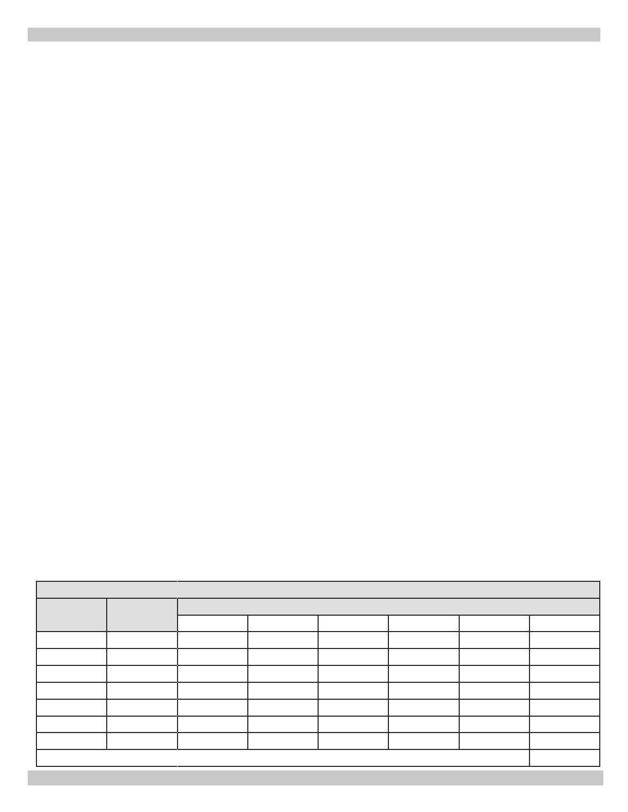
Table 3 - Minimum Room Volume, Indoor Air Only*
Input Mbh
Standard
Method
Known Air Inltration Rate Method ACH (Air Changes Per Hour)
0.1 0.2 0.3 0.4 0.5 0.6
75 3750 15750 7875 5250 3938 3150 2625
112.5 5625 23625 11813 7875 5906 4725 3938
150 7500 31500 15750 10500 7875 6300 5250
187.5 9375 39375 19688 13090 9844 7875 6563
255 11250 47250 23625 15750 11813 9450 7875
262.5 13125 55125 27563 18375 13781 11025 9188
299 14950 62790 31395 20930 15698 12558 10465
* Table values based on boiler only. Add volume for any additional appliances.
7
CONNECTING SUPPLY AND RETURN PIPING
RELIEF VALVE
DISCHARGE
LINE
Check local
codes for
maximum
distance
from oor
or allowable
safe point of
discharge.
WARNING
Burn or Scald Hazard. Discharge line shall be installed to relief valve outlet connection to avoid burns,
scalding, or water damage due to discharge of steam and/or hot water during operation.
Discharge line shall:
Connect to relief valve outlet and piped down to safe point of disposal. Check local codes for maximum
distance from oor or allowable safe point of discharge.
• Be of pipe size equal to or greater than that of the relief valve outlet over the entire length of discharge
line.
• Have no intervening shutoff valve between safety relief valve and discharge to atmosphere (do not plug
or place any obstruction in discharge line.
• Terminate freely to atmosphere where any discharge will be clearly visible and at no risk of freezing.
• Allow complete drainage of the valve and the discharge line.
• Be independently supported and securely anchored to avoid applied stress on the relief valve.
• Be as short and straight as possible.
• Terminate with plain end (not threaded).
Be constructed of material suitable for exposure to temperatures of 375°F (191°C); or greater.
Refer to local codes and appropriate ASME Boiler and Pressure Vessel Code for additional installation
requirements.
!
Figure 1 - Safety Relief Valve
8
CONNECTING SUPPLY AND RETURN PIPING
WARNING
Burn and scald hazard. Safety relief valve could
discharge steam or hot water during operation.
Install discharge piping per these instructions.
!
Figure 2 - Temperature Pressure Gauge
1.
Install discharge piping from safety relief valve. See
Warning, Page 7.
2.
Install temperature pressure gauge.
Apply pipe sealant to threads on shaft of gauge.
Thread gauge into supply water tee. See Figure 2.
NOTICE
Do not tighten gauge by hand. Gauge should be
tightened using crescent wrench or 9/16” open end
wrench. See Figure 2.
3.
Connect supply and return lines to boiler. Connections
may require additional ttings and parts, as shown on
diagrams.
4.
Boiler is equipped with 1
1/4” supply and return
connections on both left and right sides of boiler.
Verify clean water supply is available to water inlet valve.
Install sand strainer when water supply is from a well or
pump.
Install hot water boiler above radiation level or as
required by Authority having jurisdiction install low water
cutoff device at time of installation. Periodic inspection
is necessary, as is ushing of oat type devices, per
manufacturers specic instruction.
FOR USE WITH COOLING UNITS
A. Boiler used in connection with refrigeration system,
must be installed so that chilled medium is piped in
parallel with heating boiler. Appropriate valves must be
used to prevent chilled medium from entering heating
boiler. See Figure 4 page 9.
B. Boiler connected to heating coils located in air handling
units where they may be exposed to refrigerated air
circulation, piping system shall be equipped with ow
control valves or other automatic means to prevent
gravity circulation of boiler water during cooling cycle.
LOW WATER TEMPERATURE AND LARGE WATER
CONTENT SYSTEM (See Figures 5 and 6, Page 10.)
Signicant condensation may form in boiler and/or
venting system if boiler is operated for long period of
time with return temperatures of less than 120° F.
Condensate is corrosive and can cause severe
damage to boiler and venting system. Minimum
design return water temperature to prevent
condensation in boiler and venting is 120°F.
Minimum high limit setting is 140°F.
1.
Boiler used in heating system where design water
temperatures below 140°F are desired (e.g. radiant
oor heating), 4-way mixing valve or suitable
alternative is required to prevent low temperature low
return water from entering boiler. Follow mixing valve
manufacturer’s instructions.
2.
Boiler connected to system having large water content
(such as former gravity system), install system bypass.
See Figures 5 and 6, page 10.
3.
Boiler water reset control is used to operate boiler,
minimum reset supply water temperature setpoint
must be at least 140°F, unless mixing valve is used as
in (1) above.
9
Figure 4 - Chilled Water Piping
Figure 3- Typical Hot Water Piping
CONNECTING SUPPLY AND RETURN PIPING
10
Figure 5 - Bypass Piping - Circulator On Supply
BYPASS PIPING REQUIRED FOR HIGH MASS (LARGE WATER CONTENT) SYSTEMS
CONTROL
Control
CONNECTING SUPPLY AND RETURN PIPING
Figure 6 - Bypass Piping - Circulator On Return
11
Boilers connecting to gas vents or chimneys, vent
installations shall be in accordance with “Venting of
Equipment”, of the National Fuel Gas Code, ANSI Z223.1/
NFPA 54, or applicable provisions of local building codes.
Check Your Chimney
It must be clean, right size, properly constructed and in
good condition.
Chimney Sizing
Chimney sizing, and vent installation must be in accordance
with the National Fuel Gas Code, ANSI Z223.1/NFPA 54, or
applicable provisions of local building codes.
This is a high efciency boiler with low stack temperature.
Following recommendations are in addition to requirements
of the National Fuel Gas Code.
1. Type B double wall vent pipe is recommended for
vent connector. Single wall vent connectors should
not be used unless following conditions are true:
a) Except for basement, boiler is not installed in
unheated space.
b) Total horizontal portion of vent connector, not
including elbows is less than 5 feet in length.
2. Outside chimneys (i.e. chimneys exposed to
outdoors below roof line) should not be used unless
they are:
a) enclosed in a chase, or
b) lined with type B vent pipe, or listed exible
vent liner, or other certied chimney lining system.
3. Where possible it is recommended to common vent
boiler and water heater.
4. For multiple boiler installations, consult boiler
manufacturer for venting recommendations.
Connecting The Vent Damper And Vent Connector
Refer to Dimensions, page 2 for size and location of
vent (ue opening).
NOTICE
Damper blade on furnished vent damper has 1/2
square inch hole (approximately 3/4” diameter).
Boilers equipped with intermittent ignition, hole
should be plugged by using plug supplied with vent
damper.
1.
Position furnished vent damper on top of ue outlet
collar. Fasten damper securely to ue outlet collar with
sheet metal screws. Verify damper blade has clearance
to operate inside of diverter. Do not modify either draft
diverter or vent damper during installation.
As An Option
Damper may be installed in a horizontal or
vertical position, closer to ue outlet collar
preferred. See Figures 7, 8 and 9, and Vent
Damper Instructions.
2.
Install vent damper to service only single boiler for
which it is intended. Damper position indicator shall be
in visible location following installation. Locate damper
so it is accessible for servicing.
3.
Damper must be in the open position when appliance
main burners are operating.
4.
Boiler is equipped with factory wired harness that plugs
into vent damper.
5.
Slope pipe up from boiler to chimney not less than 1/4”
per foot.
6.
Run pipe as directly as possible with as few elbows as
possible.
7.
Do not connect to replace ue.
8.
End of vent pipe must be ush with inside face of
chimney ue. Use a sealed-in thimble for chimney
connection.
Sections of vent pipe should be fastened with sheet
metal screws to make piping rigid. Horizontal potions of
vent system must be supported to prevent sagging. Use
stovepipe wires every 5’ to support pipe from above. If
vent pipe must go through crawl space, double wall vent
pipe should be used. Where vent pipe passes through
combustible wall or partition, use ventilated metal thimble.
Thimble should be 4 inches larger in diameter than vent
pipe.
Minimum Vent Pipe Clearance
Wood and other combustible materials must not be closer
than 6” from any surface of single wall metal vent pipe.
Listed Type B vent pipe or other listed venting systems
CHIMNEY AND VENT PIPE CONNECTION
12
shall be installed in accordance with their listing.
Removing Existing Boiler From Common Venting
System
When an existing boiler is removed from common venting
system, common venting system is likely to be too large for
proper venting of appliances remaining connected to it.
At time of removal of existing boiler, following steps shall
be followed with each appliance remaining connected to the
common venting system placed in operation, while other
appliances remaining connected to common venting system
are not in operation.
1.
Seal any unused openings in the common venting
system.
2.
Visually inspect the venting system for proper size and
horizontal pitch and determine there is no blockage or
restriction, leakage, corrosion and other deciencies
which could cause an unsafe condition.
3.
Insofar as is practical, close all building doors and
windows and all doors between the space in which the
appliances remaining connected to the common venting
system are located and other spaces of the building.
Turn on clothes dryers and any appliance not connected
to the common venting system. Turn on any exhaust
fans, such as range hoods and bathroom exhausts, so
they will operate at maximum speed. Do not operate a
summer exhaust fan. Close replace dampers.
4.
Place in operation the appliance being inspected. Follow
the lighting instructions. Adjust thermostat so appliance
will operate continuously.
5.
Test for spillage at the draft hood relief opening after
5 minutes of main burner operation. Use the ame of
a match or candle, or smoke from a cigarette, cigar or
pipe.
6.
After it has been determined that each appliance
remaining connected to the common venting system
properly vents when tested as outlined above, return
doors, windows, exhaust fans, replace dampers and
CHIMNEY AND VENT PIPE CONNECTION
any other gas-burning appliance to their previous
conditions of use.
7.
Any improper operation of the common venting system
should be corrected so the installation conforms with
the National Fuel Gas Code, ANSI Z223.1/NFPA 54.
When re-sizing any portion of the common venting
system, the common venting system should be re-sized
to approach the minimum size as determined using the
appropriate tables in Chapter 13 of the National Fuel
Gas Code, ANSI Z223.1/NFPA 54.
Vent connectors serving appliances vented by natural draft
shall not be connected into any portion of mechanical draft
systems operating under positive pressure.
13
VENT DAMPER OPERATION
Figure 7 Figure 8
For safe, efcient operation, vent damper and all ue
product carrying areas of appliance must be checked
annually, with particular attention given to deterioration
from corrosion or other sources. If you see corrosion or
other deterioration, contact your heating contractor for
repairs. Check vent damper operation as follows:
When boiler is off, check vent damper positions
indicator points to closed position. See Figure 9.
Turn thermostat or controller up to call for heat and
check vent damper indicator points to open position.
See Figure 9.
Turn thermostat or controller down again and check
damper position indicator returns to closed position.
Vent Damper Manual Operation
Vent damper may be placed in open position to permit
burner operation by using “HOLD DAMPER OPEN” switch,
located on damper controller. Thermostat will control
burner ring as before, while damper will remain open.
DO NOT turn damper open manually or motor damage will
result. Set switch to “AUTOMATIC OPERATION” to close
vent damper during burner off cycle.
For further information, and vent damper
troubleshooting guide, refer to manual packaged with
vent damper.
Inspect vent damper at least once a year by a
qualied service technician.
Figure 9 - Vent Damper Position Indicator
14
GAS SUPPLY PIPING
Check Gas Supply
Gas pipe to your boiler must be correct size for length of
run and for total BTU per hour input of all gas utilization
equipment connected to it. Be sure your gas line complies
with local codes and gas company requirements. See Table
4 for proper pipe size.
Connecting The Gas Piping
Gas line enters boiler from right side.
Use only piping materials and joining methods listed
as acceptable by the authority having jurisdiction, or in
the absence of such requirements, by the National Fuel
Gas Code, ANSI Z223.1/NFPA 54.
Use pipe joint compound suitable for LP gas on male
threads only.
Use ground joint unions.
Install sediment trap upstream of gas controls.
Use two pipe wrenches when making connection to gas
valve to keep it from turning.
Install manual shut-off valve in vertical pipe about 5
feet above oor.
Tighten all joints securely.
Propane gas connections should only be made by
licensed propane installer.
Two-stage regulation should be used by propane
installer.
Propane gas piping should be checked out by propane
installer.
CHECKING GAS PIPING
DANGER
Fire Hazard. Do not use matches, candles, open
ames, or other methods providing ignition source.
Failure to comply will result in death or serious
injury.
!
Pressure test boiler and gas connection before placing
boiler in operation.
Pressure test over 1/2 psig (3.5 kPa). Disconnect
boiler and its individual gas shutoff valve from gas
supply system.
NATURAL GAS
Pipe Capacity - BTU Per Hour Input
Includes Fittings
Length of
Pipe - FT
½” ¾” 1” 1¼”
20 92,000 190,000 350,000 625,000
40 63,000 130,000 245,000 445,000
60 50,000 105,000 195,000 365,000
PROPANE GAS
Pipe Capacity - BTU Per Hour Input
Includes Fittings
Length of
Pipe - FT
Copper Tubing * Iron Pipe
⅝” ¾” ½” ¾”
20 131,000 216,000 189,000 393,000
40 90,000 145,000 129,000 267,000
60 72,000 121,000 103,000 217,000
* Outside diameter
Measure length of pipe or tubing from gas meter or
propane second stage regulator.
Table 4 - GAS PIPE SIZES
Figure 10 - Gas Piping
Pressure test at 1/2 psig (3.5 kPa) or less. Isolate
boiler from gas supply system by closing manual gas
shutoff valve.
Locate leakage using gas detector, noncorrosive
detection uid, or other leak detection method
acceptable to authority having jurisdiction. Do
not use matches, candles, open ames, or other
methods providing ignition source.
Correct leaks immediately and retest.
CAUTION
WHAT TO DO IF YOU SMELL GAS
• Do not try to light any appliance.
• Do not touch any electrical switch; do not use
any phone in your building.
• Immediately call your gas supplier from a
neighbor’s phone. Follow gas supplier’s
instructions.
If you cannot reach your gas supplier, call the re
department.
!
15
ELECTRICAL WIRING
Electrically bond boiler to ground in accordance with
requirements of authority having jurisdiction. Refer to
National Electrical Code, ANSI/NFPA 70.
ELECTRIC POWER SUPPLY
Run separate 120 volt circuit from separate over current
protective device in electrical service entrance panel. This
should be a 15 ampere circuit. Locate shut-off switch at
boiler. It must be turned off during any maintenance.
Connect 120 volt power supply to control leads L1 (HOT)
and L2.
Run a 14 gauge or heavier copper wire from boiler to
grounded connection in service panel or properly driven
and electrically grounded ground rod.
THERMOSTAT INSTALLATION
1.
Thermostat should be installed on an inside wall about
four feet above the oor.
2.
NEVER install a thermostat on an outside wall.
3.
Do not install a thermostat where it will be affected
by drafts, hot or cold pipes, sunlight, lighting xtures,
televisions, a replace, or a chimney.
4.
Check thermostat operation by raising and lowering
thermostat setting as required to start and stop the
burners.
5.
Instructions for the nal adjustment of the thermostat
are packaged with the thermostat (adjusting heating
anticipator, calibration, etc.)
Set heat anticipator at .2 amps. 24 volt thermostat
connects to aquastat terminals T and TV.
VENT DAMPER WIRING
Boiler is equipped with factory wired harness with 4 pin
molex plug, that plugs into 4 pin molex receptacle inside
vent damper operator.
Vent damper must be connected for boiler to operate.
If original wire as supplied with this appliance
must be replaced, replace with type 105°C
thermoplastic wire or its equivalent.
WARNING
Electrical shock hazard. Turn OFF electrical power
supply at service panel before making electrical
connections. Failure to do so could result in death
or serious injury.
!
NOTICE
Label all wires prior to disconnection when servicing
controls. Wiring errors can cause improper and
dangerous operation. Verify proper operation after
servicing.
16
WIRING DIAGRAMS
Figure 11 - Electronic Ignition Control
WARNING
Modication, substitution or elimination of factory
equipped, supplied or specied components may
result in personal injury or loss of life.
!
17
STARTING YOUR BOILER
FILLING SYSTEM WITH WATER
Close air vents on all radiation units. Open valves to
these units.
Verify boiler and expansion tank drain valves are closed.
Close drain tting on air bleed screw.
Open valve in line from boiler to expansion tank. Open
water inlet to your boiler and leave it open. Start with
lowest radiation unit. Open air vent on this unit. When
all air has escaped and water starts to ow from vent,
close it.
Go to next radiation unit, and repeat process. Repeat
until you have covered every radiation units in the system
(ending up at highest unit in system).
If your units have automatic vents, this manual venting is
unnecessary but it will speed up the proper lling of your
system.
If your system is closed expansion tank system, you may
leave it open to rell system automatically as needed.
Check temperature pressure gauge. Not position of hand
indicating pressure. This should be between 10 and 15 psi.
Any lowering of this movable hand below 10 psi. indicates
loss of water due to leakage. Automatic ll valve should
compensate for this. Instructions are packaged with valve.
NOTICE
Never run water in a hot empty boiler.
18
LIGHTING INSTRUCTIONS
OFF
ON
INLET
GAS CONTROL
KNOB
PILOT ADJUSTMENT
(UNDER CAP SCREW)
PILOT
OUTLET
OUTLET
WIRING
TERMINALS (2)
INLET
PRESSURE
TAP
TERMINALS
(2)
GROUND
PRESSURE
TAP
PRESSURE REGULATOR
ADJUSTMENT
(UNDER CAP SCREW)
OUTLET
F. Remove front panel.
G. Rotate the gas control knob clockwise to “OFF”.
TO TURN OFF GAS TO APPLIANCE
1. Set the thermostat to lowest setting.
2. Turn off all electric power to the appliance if
service is to be performed.
3. Push in gas control knob slightly and turn
clockwise to “OFF” Do not force.
WARNING
If you do not follow these instructions
exactly, a re or explosion may result
causing property damage, personal injury
or loss of life.
• This appliance is equipped with an ignition device
which automatically lights burner. Do NOT try to
light this burner by hand.
• Before operating smell all around appliance area
for gas. Be sure to smell next to oor because
some gas is heavier than air and will settle to the
oor.
Use only your hand to turn the gas shutoff
valve. Never use tools. If valve will not turn
by hand, do not try to repair it, call a qualied
service technician. Force or attempted repair may
result in re or explosion.
Do not use this appliance if any part has
been under water. Immediately call a qualied
service technician to inspect appliance and to
replace any part of control system and any gas
control which has been under water.
!
LIGHTING PROCEDURE FOR BOILER WITH
INTERMITTENT PILOT SYSTEM
For Your Safety, Read Before Operating!!
A. This appliance is equipped with an ignition device
which automatically lights the pilot. Do not try to light
appliance by hand.
CAUTION
WHAT TO DO IF YOU SMELL GAS
• Do not try to light any appliance.
• Do not touch any electrical switches; do not use
any phone in your building.
• Immediately call your gas supplier from a
neighbor’s phone. Follow the gas supplier’s
instructions.
If you cannot reach your gas supplier, call the re
department.
!
B. STOP! Read the safety information above.
C. Set the thermostat to lowest setting.
D. Turn off all electric power to the appliance.
E. This appliance is equipped with an ignition device which
automatically lights the pilot. Do not try to light the
pilot by hand.
Figure 12 - Automatic Gas Valve
H. Wait ve (5) minutes to clear out any gas. Then
smell for gas, including near the oor. If you smell
gas, STOP! Follow the safety information “What To Do
If You Smell Gas”. If you don’t smell gas, go to next
step.
I. Rotate gas control knob counterclockwise to
“ON”.
J. Turn on all electric power to the appliance.
K. Set thermostat to desired setting.
L. If appliance will not operate, follow the instructions
“To Turn Off Gas To Appliance” and call your service
technician or gas supplier.
19
OPERATING YOUR BOILER
AUTOMATIC GAS VALVE
Automatic Gas Valve opens or closes according to
heat requirements of thermostat and temperature
limit control. It closes if pilot goes out. Each
individual control must be operating correctly before
any gas can pass to burners. Any one control can
hold gas supply from burner regardless of demand of
any other control.
SAFETY PILOT
Safety Pilot prevents ow of gas to burner if pilot
goes out, or will not ignite.
GAS VALVE SAFETY SHUTDOWN TEST
Ignition system safety shutoff device must be tested after
placing boiler in operation.
RELIGHT
Electric and gas shall be off for 5 minutes before
relighting.
THERMOSTAT
Keep it set at desired room temperature. If windows
are to be opened or heat is not needed, move
thermostat pointer to lower setting.
NOTICE
In event of failure of any component, system
will not operate or will go into safety lockout.
System is completely self-checking. On
every call for heat, each component must
be functioning properly to permit operation.
Safety lockout system has to be reset by
turning thermostat to lowest setting for one
minute, then back to normal setting.
ADJUST PILOT BURNER
Pilot ame should surround 3/8” to 1/2” of the pilot
sensor. See Figure 16. If ame needs adjusting, do it
as follows:
1.
Remove screw cover over pilot adjusting screw.
2.
Insert small screwdriver and adjust ame as needed.
Turn screw counterclockwise to increase ame, clockwise
to decrease.
3.
Replace screw cover over pilot adjusting screw.
MAIN BURNER(S)
Main burners do not require primary air adjustment and
are not equipped with primary air shutters.
Main burner ames form sharp blue inner cones in softer
blue outer mantel, with no yellow.
Puffs of air from blowing on ame or stamping on oor
will cause ames to turn orange momentarily. This is
not unusual. Remain still when observing main burner
ames.
If ame appearance is not correct, check main burner
orices, burner throat and ame ports for dust and
lint obstruction. It may be necessary to remove rollout
shield to observe main burner ames. Replace rollout
shield after observation. Refer to Figure 14.
Figure 14 - Burner
ADJUST LIMIT CONTROLS
Instructions for each control are included with controls.
Settings can be changed.
See Control Section page 24.
Figure 13 - Pilot Flame
20
OPERATING YOUR BOILER
CHECK THERMOSTAT OPERATION
A. When set above temperature indicated on
thermostat, boiler should ignite.
B. Verify thermostat turns boiler off when room
temperature reaches selected setting and starts
boiler operating when room temperature falls a
few degrees.
C. After setting limit control to limit setting, check to
see if it shuts off gas supply to burners. Turn your
thermostat up to call for heat and let boiler run
until temperature of water reaches limit setting.
Gas valve should shut off and circulator running
until thermostat is satised, or water cools enough
to restart burners through limit control.
D. Set thermostat for desired temperature. Conditions
in your home and location of thermostat will govern
this setting.
  • Page 1 1
  • Page 2 2
  • Page 3 3
  • Page 4 4
  • Page 5 5
  • Page 6 6
  • Page 7 7
  • Page 8 8
  • Page 9 9
  • Page 10 10
  • Page 11 11
  • Page 12 12
  • Page 13 13
  • Page 14 14
  • Page 15 15
  • Page 16 16
  • Page 17 17
  • Page 18 18
  • Page 19 19
  • Page 20 20
  • Page 21 21
  • Page 22 22
  • Page 23 23
  • Page 24 24
  • Page 25 25
  • Page 26 26
  • Page 27 27
  • Page 28 28

Dunkirk WPSB-3D Installation & Operation Manual

Category
Water heaters & boilers
Type
Installation & Operation Manual

Ask a question and I''ll find the answer in the document

Finding information in a document is now easier with AI