
NORTEK GLOBAL HVAC, LLC
Wired Controller WRC1
Owner's Manual
Controller
Please read this owner’s manual carefully before operation and retain it for future reference
Specifications & illustrations subject to change without notice or incurring obligations

Wired Controller WRC1
2
User Notices
◆The power supply for all indoor units must be unified.
◆Don’t install the wired controller at wet or sunny locations.
◆Do not knock, throw or frequently disassemble the wired controller.
◆Do not operate the wired controller with wet hands.
◆In one system network, you must set one indoor unit as the master
indoor unit, other indoor units are slave indoor units .
◆ The operation mode of the system is based on that of the master indoor
unit. The master indoor unit can switch to any modes, while the slave unit
can’t switch to the mode that is conflicting with the master indoor unit.
◆ When the master indoor unit changes mode and causes the operation
mode of the slave indoor unit to conflict with that of the system, then the
operation mode of the slave unit will switch to the operation mode of the
system automatically.
◆When two wired controllers control one (or more) indoor unit(s), the
addresses of the wired controllers should be different.
◆Functions with “*” are optional for indoor units. If a function is not
included in an indoor unit, the wired controller can’t set the function, or
setting of this function is invalid to the indoor unit.

Wired Controller WRC1
3
CONTENTS
1 DISPLAY .................................................................................................................. 4
1.1 LCD OF WIRED CONTROLLER ................................................................... 4
1.2 LCD DISPLAY INSTRUCTION ...................................................................... 5
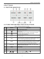
2 BUTTONS ............................................................................................................... 7
2.1 BUTTON GRAPHICS ..................................................................................... 7
2.2 FUNCTION INSTRUCTION OF BUTTONS ................................................. 7
3 INSTALLATION AND COMMISSIONING .......................................................... 8
3.1 INSTALLATION OF WIRED CONTROLLER ............................................... 9
3.2 COMMISSIONING ........................................................................................ 13
4 OPERATION INSTRUCTIONS .......................................................................... 20
4.1 ON/OFF .......................................................................................................... 20
4.2 MODE SETTING ........................................................................................... 20
4.3 TEMPERATURE SETTING .......................................................................... 21
4.4 FAN SETTING................................................................................................ 22
4.5 TIMER SETTING ........................................................................................... 22
4.6 SWING SETTING .......................................................................................... 25
4.7 QUIET SETTING ........................................................................................... 26
4.8 SLEEP SETTING........................................................................................... 27
4.9 AIR SETTING* ............................................................................................... 28
4.10 LIGHT ON/OFF SETTING.......................................................................... 29
4.11 SAVE SETTING ........................................................................................... 30
4.12 FILTER CLEAN REMINDER SETTING ................................................... 31
4.13 X-FAN SETTING ......................................................................................... 33
4.14 OUT SETTING ............................................................................................. 33
4.15 REMOTE SHIELD FUNCTION .................................................................. 33
4.16 CHILD LOCK FUNCTION .......................................................................... 34
4.17 GATE-CONTROL FUNCTION ................................................................... 34
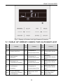
5 ERROR DISPLAY ................................................................................................ 34
5.1 TABLE OF ERROR CODES FOR OUTDOOR UNIT ................................ 35
5.2 TABLE OF ERROR CODES FOR INDOOR UNIT .................................... 37
5.3 TABLE OF DEBUGGING CODES ............................................................... 37
5.4 TABLE OF STATUS CODES ........................................................................ 38

Wired Controller WRC1
4
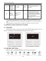
1 DISPLAY
Fig. 1.1 Appearance of wired controller
1.1 LCD OF WIRED CONTROLLER
Fig. 1.2 LCD graphics of wired controller

Wired Controller WRC1
5
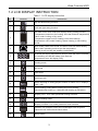
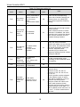
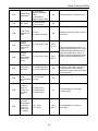
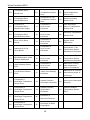
1.2 LCD DISPLAY INSTRUCTION
Table 1.1 LCD display instruction
No. Symbols Instructions
1
Up and down swing function
2
*
Left and right swing function
3
It's valid under Save mode and displays during setting process.
Temperature lower limit for Cooling: Limit the minimum temperature
value under Cooling or Dry mode.
Temperature upper limit for Heating: Limit the maximum
temperature value under Heating, Space Heating or 3D Heating
mode.
4
*
Auto mode (Under Auto mode, the indoor units will automatically
select their operating mode as per the temperature
change so as to make the ambient comfortable.)
5
It shows the setting temperature value(In case the wired controller
is controlling a Fresh Air Indoor Unit, then the
temperature zone will display FAP)
6
Cooling mode
7
Dry mode
8
Fan mode
9
Heating mode
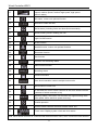
10
When inquiring or setting project number of indoor unit, it displays
"NO." icon
11
*
Floor Heating mode (When Heating and Floor Heating
simultaneously shows up, it indicates 3D Heating is activated.)
12
Display "SET" icon under parameter setting interface
13
-
*
Space Heating mode
14
Display "CHECK" icon under parameter view interface
15
Outdoor unit operates under Save mode/upper limit of system
capacitor less 100%/remote Save status
16
Sleep status

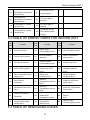
Wired Controller WRC1
6
17
Current set fan speed (including auto, low speed, medium-low
speed, medium speed, medium-high speed, high speed
and six status)
18
*
Air status, Indoor unit optional function
19
Remind to clean the filter
20
Quiet status (including Quiet and Auto Quiet two status)
21
*
Allow auxiliary electric heating On icon
22
Light On/Off function
23
X-fan function
24
*
Health function, Indoor unit optional function
25
*
Reserved function
26
Out function
27
Outdoor unit defrosting status
28
Gate-control function
29
Shielding status
30
Child Lock status
31
One wired controller controls multiple indoor units
32
Save status of indoor unit
33
It indicates the current wired controller is the slave wired controller
(address of wired controller is 02)
34
Memory status (The indoor unit resumes the original setting state
after power failure and then power recovery)
35
Invalid operation
36
Current wired controller connects master indoor unit
37
Timer zone: Display system clock and timer status
Note: When wired controller is connected with different indoor units, some f unctions will be different

Wired Controller WRC1
7
2 BUTTONS
2.1 BUTTON GRAPHICS
Fig. 2.1 Button graphics
2.2 FUNCTION INSTRUCTION OF BUTTONS
Table 2.1 Function instruction of buttons
No. Buttons Instructions
1 ENTER/CANCEL Select and cancel function
2
(1) Set operating temperature of indoor unit
(2) Set Timer
(3) Switch Quiet mode, Air grade, Clean grade, set upper
and lower temperature limit under Save mode
(4) Set and inquiry parameter
5
3 SLEEP Set Sleep mode
4 FAN
Switch among auto, low speed, low-medium speed, medium
speed, medium-high speed and high speed status
6 MODE
Switch Auto, Cooling, and Dry, Fan, Heating, Floor Heating,
3D Heating and Space Heating modes for indoor unit. (Note:
The Floor Heating, 3D Heating and Space Heating function
icon will show up when the unit has those functions.)
7 FUNCTION
Switch among Air, Quiet, Light, Health, Out, Save, Clean,
E-heater and X-fan functions.
8 TIMER Timer setting
9 SWING Set up and down swing status
10 ON/OFF Indoor unit On/Off
2+5
+
Simultaneously press “ ” and “ ” for 5s to enter or
cancel the Child Lock function.

Wired Controller WRC1
8
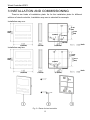
3 INSTALLATION AND COMMISSIONING
There’re two kinds of installation plate. As for the installation plate for different
editions of wired controller, Installation way one is selected for example.
Installation way one:
Installation way two:
Fig. 3.1 Parts of wired controller
(4-3/8 inch)
(4-3/8
inch)
(7-8 inch) (1-5/8 inch)
(7/8 inch)
/ inch
/ inch
(1/8 inch)
(1/4 inch)
(1-5/8
inch
)
(3-1/4
inch)
(4-3/8 inch)
(4-3/8
inch)
(7-8 inch) (1-5/8 inch)
(7/8 inch)
(1/8 inch)
(1-5/8
inch
)
(3-1/4
inch)

Wired Controller WRC1
9
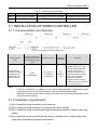
Wire material
type
Total length of
communication line
between indoor unit
and wired controller
L (m)
Wire size (mm
2
)
Material
standard
Remarks
Light/Ordinary
Polyvinyl chloride
sheathed cord.
(60227 IEC 52
/60227 IEC 53)
L≤250
2×0.75-2×1.25
(2×AWG18
-2×AWG16)
IEC
60227-5:
2007
(1)Total length of
communication line can't
exceed 250m
(2)The cord shall be
Circular cord (the cores
shall be twisted together).
(3)If unit is installed in
places with intense
magnetic field or strong
interference, it is necessary
to use shielded wire.
Note:
① If the air conditioner is installed at the strong electromagnetic interference place,
communication line of the wired controller must use shielding twisted pair.
② Materials of communication line for wired controller must be selected according to this
instruction manual strictly
3.1.2 Installation requirements
(1) Don’t install the wired controller in wet locations.
(2) Don’t install the wired controller in locations with direct sunlight.
(3) Don’t install the wired controller near high-temperature objects or where water may
splash.
(4) Don’t install the wired controller directly facing a window. Also, install it away from
other wired controllers to prevent interference.
(L≤820 f
eet)
(820 f
eet).
3.1
INSTALLATION OF WIRED CONTROLLER
3.1.1 Communication Line Selection
Fig. 3.2 Length of communication line
Fig. 3.1.2 Parts of wired controller
No. 1 2 3
Name Panel of wired controller Self-tapping Screw ST3.9X25 MA Soleplate of wired controller
Q'ty 1 3 1

Wired Controller WRC1
10
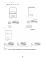
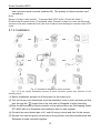
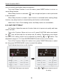
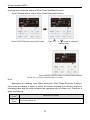
3.1.3 Wiring Requirements
There are four network wiring methods between wired controller and indoor unit:
Fig. 3.3 One wired controller controls one indoor unit Fig. 3.4 Two wired controllers control one
indoor unit
Fig. 3.5 one wired controller controls multiple indoor units simultaneously

Wired Controller WRC1
11
Fig. 3.6 Two wired controllers control multiple indoor units simultaneously
Wiring instructions:
(1) When one wired controller controls multiple indoor units simultaneously, the wired
controller can connect to any one indoor unit, but the connected indoor unit must be
the same series indoor unit. The total quantity of indoor unit controlled by one wired
controller can't exceed 16 sets, and the connected indoor unit must be within the
same indoor unit's network. Wired controller must set quantity of the connected
indoor units. Please refer to 3.2.3 Parameters Setting.
(2) When two wired controllers control one indoor unit, the addresses of those two
wired controllers should be different. Please refer to 3.2.3 parameter setting.
(3) When two wired controllers control multiple indoor units, the wired controller can be
connected to any one indoor unit, while the connected indoor unit should be the
same series indoor unit. The addresses of those two wired controllers should be
different. Please refer to 3.2.3 parameter setting. The total quantity of indoor units
controlled by wired controllers can't be more than 16 sets and all connected indoor
units must be within the same indoor unit network. Wired controller must set
quantity of the connected indoor units. Please refer to 3.2.3 Parameters Setting.
(4) When one (or two) wired controller(s) control(s) multiple indoor units at the same
time, the controlled indoor unit's setting should be the same.
(5) Wiring of the wired controller and indoor unit network must be according to one of
the four wiring method as shown in fig 3.3-3.6. As for the connection method shown
in fig 3.4 and 3.6, there should be only one master wired controller (address is 01)

Wired Controller WRC1
12
and one slave wired controller (address 02). The quantity of wired controller can't
exceed two.
Note:
Series of indoor units include:①Common Multi VRF Units;②Fresh Air Units;③
Double-heat Sources Units;④Combined Units; Except for fresh air units, double-heat
sources units and combined units, the rest of indoor units belong to common multi VRF
units.
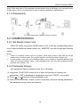
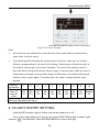
3.1.4 Installation
Fig. 3.7 Installation diagram for wired controller
Fig. 3.7 is the simple installation process of wired controller; please pay attention to the
following items:
(1) Before installation, please cut off the power for the indoor unit.
(2) Pull out the two-core twisted pair from the installation hole on wall, and then pull this
wire through the " ” shape hole at the rear side of Soleplate of wired controller.
(3)Stick the bottom plate of wired controller on the wall and then use Self-tapping Screw
ST3.9X25 MA to fix Soleplate and installation hole on wall together.
(4) Connect two-core twisted pair to H1 and H2 wiring column and then fix the screws.
(5) Set two-core into the groove at left side of wiring column, and then bundle panel and
Soleplate of wired controller together.

Wired Controller WRC1
13
Note: If the wire size of the selected communication line is too large, you can peel some
sheath layer off the communication wire to satisfy installation requirements.
3.1.5 Disassembly
Fig. 3.8 Disassembly diagram of wired controller
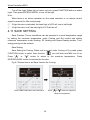
3.2 COMMISSIONING
3.2.1 Set Master Indoor Unit
Under Off status, long press MODE button for 5s to set the corresponding indoor
unit of wired controller as master indoor unit. “MASTER” icon will be light after finishing
setting.
Note:
① There is a master indoor unit in a system; other slave indoor units can be set as
master unit, in which case, the original master unit will become a slave unit.
② In one system, only one set of master indoor unit is allowed. If system detects that
there are several master units, it will designate the unit with the smallest project
number as a master unit.
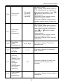
3.2.2 Parameter Enquiry
Unit parameters can be checked in unit On or Off status.
(1) Long press “FUNCTION” button for 5s to enter the interface of viewing unit
parameters. “C00” is displayed in temperature zone and “CHECK” icon is light;
(2) Press “ ” or “ ” button to select parameter code;
(3) Press “ENTER/CANCEL” button to return to last step until exits viewing parameters.
The parameter enquiry list is as following:

Wired Controller WRC1
14
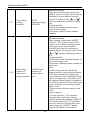
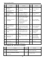
Table 3.1 Parameters viewing list
Param
eter
code
Parameter
name
Parameter
range
Viewing method
C00
Entrance of
adjustable
parameter
--
In “C00” status, Timer zone shows the
current indoor unit project number.
When one wired controller is
controlling multiple indoor units, then
only the smallest project number will be
displayed.
C01
View the
project number
of indoor unit
and locate the
faulted indoor
unit
1-255;
Project number
of online indoor
unit
Operation method:
Enter viewing, press MODE button in
“C01” status to enter the interface of
viewing indoor unit project number.
Press “ ” or “ ” button to select the
project number of indoor unit.
Display method:
Temperature zone: displays error
codes of the current indoor unit( The
temperature zone will display the error
codes in turn with an interval of 3
seconds if there are several
malfunctions in one indoor unit.)
Timer zone: displays present indoor
unit project number /C5 malfunction of
project number conflict
Note:
1) If master indoor unit exists in current
indoor unit network, “MASTER” icon
will be bright under “C01” interface.
After entering the interface of viewing
project number, “MASTER” icon will be
bright only when the project number of
master indoor unit is selected.
2) System will not exit “C01” viewing
automatically. User has to exit this
interface manually.
C03
View the
indoor unit
quantity of the
system
network
1-80
Timer zone: display indoor unit quantity
of the system

Wired Controller WRC1
15
C06
View priority
operation
00: normal
operation
01: priority
operation
Operation method:
Enter viewing: press MODE button in
“C06” status to enter the interface of
viewing priority operation. Press “ ” or
“ ” button to select indoor unit.
Display method:
Temperature zone: displays current
indoor unit project number;
Timer zone: displays current priority
operation setting value of indoor unit.
C07
View indoor
ambient
temperature
--
Operation method:
Enter viewing: press MODE button in
“C07” status to enter the interface of
viewing indoor ambient temperature.
Press “ ” or “ ” button to select
indoor unit.
Display method:
Temperature zone: displays current
indoor unit project number;
Timer zone: displays indoor ambient
temperature.
C08
View Filter
Clean
Reminder time
4-416: days
Timer zone: displays Filter Clean
Reminder time
C09
View address
of wired
controller
01, 02
Timer zone: displays the address of
wired controller
C11
View the
indoor unit
quantity in the
case that one
wired
controller
controls
several indoor
units at the
same time
1-16
Timer zone: displays the indoor unit
quantity controlled by the wired
controller
C12
View outdoor
ambient
temperature
-
Timer zone: displays outdoor ambient
temperature

Wired Controller WRC1
16
C17
View indoor
relative
humidity
20-90
relative humidity
20%-90%
Operation method:
Enter into review process and press
“MODE” button to enter into the review
interface of indoor relative humidity
under C17 status. Press “ ” or “ ”
button to switch the number of indoor
unit.
Display method:
Temp area: display current indoor
unit’s project number
Timer zone: display indoor relative
humidity
C18
One-button
viewing of
indoor unit
project number
1-255:Project
Number of
online indoor
unit
Operation method:
Enter viewing, short-press “MODE”
button in “C18” status to turn on the
function of one-button viewing indoor
unit project code, and the wired
controller will enter the interface of
viewing indoor unit project code. Press
“ ” or “ ” button to select the indoor
unit.
Display method:
Temperature zone: displays number of
the current indoor unit
Timer zone: displays project number of
indoor unit
Note:
1) After turning on the one-button
viewing function, each wired controller
of the entire system will display the
project number of its controlling indoor
unit on its timer zone. (The timer zone
will display different project numbers in
turn with an interval of 3 seconds if one
wired controller is controlling multiple
indoor units.)
2) Slave wired controller cannot view
“C18”.
Cancel method:
1) If user exits the “C18” interface
manually, the one-button viewing
function will be immediately turned off.
2) If system exits the “C18” interface
due to no action in 20 seconds, user
has to press the “ON/OFF” button
under on/off status to cancel this

Wired Controller WRC1
17
function.
3) After the one-button viewing function
is turned on, pressing the “ON/OFF”
button of any wired controller of the
same system network under on/off
status will cancel this function.
C20
View the air
outlet
temperature of
Fresh Air
Indoor Unit*
--
Operation method:
Enter viewing, short-press “MODE”
button in “C20” status to enter the
interface of viewing air outlet
temperature of Fresh Air Indoor Unit.
Press “ ” or “ ” button to select the
indoor unit.
Display method:
Temperature zone: displays current
indoor unit project number
Timer zone: displays air outlet
temperature of Fresh Air Indoor Unit
Note: only applicable to Fresh Air
Indoor Unit.
Note:
① Under parameter viewing status, FAN, TIMER, SLEEP and SWING buttons are
invalid. Press “ON/OFF” button to go back to the home page, while not to turn
on/off the unit.
② Under parameter viewing status, the signal from remote controller is invalid.
3.2.3 Parameter Setting
Unit parameters can be set in unit On or Off status.
(1) Long press FUNCTION button for 5s and the temperature zone displays “C00”; long
press FUNCTION button for another 5s to enter the interface of setting wired
controller parameters. “P00” is displayed in temperature zone;
(2) Press “ ” or “ ” button to select parameter code. Press MODE button to enter
parameter setting. At that time, parameter value is blinking. Press “ ” or “ ”
button to adjust the parameter value and press ENTER/CANCEL button to finish
setting.
(3) Press ENTER/CANCEL button to return to last step until exists setting parameters.
The parameter setting list is as following:

Wired Controller WRC1
18
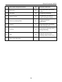
Table 3.2 Parameter setting list
Parameter
code
Parameter
name
Parameter
range
Default
value
Note
P10
Set master
indoor unit
00: do not change
current master/slave
state of indoor unit
01: set current
indoor
unit as master indoor
unit
00
When set the corresponding
indoor unit of wired controller as
master indoor unit, “MASTER”
icon will be bright after finishing
setting.
P11
Set infrared
receiver of
wired
controller
00: forbidden
01: activated
01
It can be set only through master
wired controller.
When infrared receiver of wired
controller is forbidden, the wired
controller can’t receive the signal
from remote controller and it is
operated through buttons.
P13
Set address
of wired
controller
01: master wired
controller
02: slave wired
controller
01
When two wired controllers
control one indoor unit (or several
indoor units), the addresses of the
two wired controllers should be
different. Assistant wired
controller (02) is without unit
parameter setting function except
setting its address.
P14
Set quantity
of the
connected
indoor units
00: forbid this
function
01-16: indoor unit
quantity
01
Set the corresponding value
according to the connected indoor
unit quantity.
P16
Set unit of
temperature
00:Celsius
01:Fahrenheit
00 --
P30
Set static
pressure of
indoor fan
motor
01-09: static
pressure level of
indoor fan motor
05
There are two kinds of static
pressure level:
5 levels: 03, 04, 05, 06, 07
9 levels: 01, 02, 03, 04, 05, 06,
07, 08, 09
Wired controller can be adapted
to the different types of indoor
units that it possesses 1-9 level
selection for setting static
pressure. When the indoor unit
with 5 static pressure levels
received the level setting sent by
wired controller is less than 3, it
will be settled as the 3rd level; if it
is over 7, it will be settled as the
7th level.

Wired Controller WRC1
19
P31
High ceiling
installation*
00: installation
height of standard
ceiling
01: installation
height of high ceiling
00 Only applicable to cassette units
P33 Set Timer
00: general timer
01: clock timer
00 --
P34
Clock Timer
repetition is
valid
00: once
01: repeat everyday
00
Available only when timer is set to
clock timer.
P37
Cooling
setting
temperature
under auto
mode
17°C~30°C(63°F~86
°F)
25°C
(77°F)
When the temperature unit is °C,
cooling setting temperature minus
heating setting temperature≥1°C.
When the temperature unit is °F,
cooling setting temperature minus
heating setting temperature≥2°F.
P38
Heating
setting
temperature
under auto
mode
16°C~29°C(61°F~84
°F)
20°C
(68°F)
P43
Set priority
operation
00: normal operation
01: priority operation
00
When power supply is insufficient,
the indoor units which are set to
priority operation can operate,
while other indoor units are forced
to be turned off.
P46
Clear Filter
Clean
accumulated
time
00: do not clear
01: clear
00 --
P49
Opening
angle of
indoor unit
air-return
plate*
01: angle 1(25°)
02: angle 2(30°)
03: angle 3(35°)
01
Only applicable to units with
air-return plate
P50
Air outlet
temperature
setting for
Fresh Air
Indoor Unit
in cooling*
16°C
~
30°C
(61°F~86°F)
18°C
(64°F )
Only applicable to Fresh Air
Indoor Unit

Wired Controller WRC1
20
P51
Air outlet
temperature
setting for
Fresh Air
Indoor Unit
in heating*
16°C
~
30°C
(61°F~86°F)
22°C
(72
℉
)
Only applicable to Fresh Air
Indoor Unit
P54
Union
setting of
Fresh Air
Indoor Unit*
00: without union
control
01: with union
control
00
After union function is set, Fresh
Air Indoor Unit will be turned
on/off following the on/off status
of common indoor unit. Besides,
Fresh Air Indoor Unit can also be
turned on/off manually.
Note: only applicable to Fresh Air
Indoor Unit.
Note:
① Under parameter setting status, FAN, TIMER, SLEEP and SWING button are
invalid. Press ON/OFF button to go back to home page, but not turning on/off the
unit.
② Under parameter setting status, the signal from remote controller is invalid.
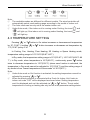
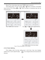
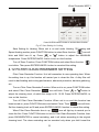
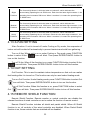
4 OPERATION INSTRUCTIONS
4.1 ON/OFF
Press ON/OFF button to turn on the unit. Press ON/OFF button again to turn off
the unit. The interfaces of On/Off status are shown in fig. 4.1 and 4.2.
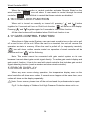
Fig. 4.1 Interface of On status Fig. 4.2 Interface of Off status
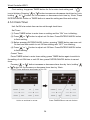
4.2 MODE SETTING
Under On status, pressing MODE button can set mode circularly as:
Page is loading ...
Page is loading ...
Page is loading ...
Page is loading ...
Page is loading ...
Page is loading ...
Page is loading ...
Page is loading ...
Page is loading ...
Page is loading ...
Page is loading ...
Page is loading ...
Page is loading ...
Page is loading ...
Page is loading ...
Page is loading ...
Page is loading ...
Page is loading ...
Page is loading ...
Page is loading ...
-
 1
1
-
 2
2
-
 3
3
-
 4
4
-
 5
5
-
 6
6
-
 7
7
-
 8
8
-
 9
9
-
 10
10
-
 11
11
-
 12
12
-
 13
13
-
 14
14
-
 15
15
-
 16
16
-
 17
17
-
 18
18
-
 19
19
-
 20
20
-
 21
21
-
 22
22
-
 23
23
-
 24
24
-
 25
25
-
 26
26
-
 27
27
-
 28
28
-
 29
29
-
 30
30
-
 31
31
-
 32
32
-
 33
33
-
 34
34
-
 35
35
-
 36
36
-
 37
37
-
 38
38
-
 39
39
-
 40
40


Unbranded Controllers and Accessories Installation guide
- Type
- Installation guide
- This manual is also suitable for
Ask a question and I''ll find the answer in the document
Finding information in a document is now easier with AI
Related papers
Other documents
-
GREE XK49 Owner's manual
-
Sinclair ASD-24BI2 User manual
-
Sinclair MV-D09BI User manual
-
-
York P-Series Single Zone System User manual
-
 SystemAir SYS WC 120 Owner's manual
-
Reznor B-HW**A3AK Installation guide
-
-
Haier AD142FCBHA Operating instructions
-
SystemAir SWC-86ED User manual
