Page is loading ...

M6500 Rev B
INSTALLATION OPERATION AND MAINTENANCE MANUAL Part number E281
MAXXo
High Efciency Condensing Stainless Steel Storage Water heaters
Please read and understand these instructions before commencing installation and leave this manual with the customer for future reference
CWH30/200, CWH30/300, CWH60/200, CWH60/300,
CWH90/200, CWH90/300, CWH120/200, CWH120/300

MAXXo Water Heater
22
Reproduction of any information in this publication by any method is not permitted unless prior
written approval has been obtained from Andrews Water Heaters.
Andrews Storage Water Heaters have been designed and manufactured to comply with current
international standards of safety. In the interests of the health and safety of personnel and the
continued safe, reliable operation of the equipment, safe working practices must be employed at
all times. e attention of UK users is drawn to their responsibilities under the Health and Safety
Regulations.
All installation and service on Andrews Water Heaters must be carried out by competent qualied
personnel and, therefore, no liability can be accepted for any damage or malfunction caused as a result
of intervention by unauthorised personnel.
Andrews Water Heaters’ policy is one of continuous product improvement and, therefore, the
information in this manual, whilst completely up to date at the time of publication, may be subject to
revision without prior notice.
Further information and assistance can be obtained from:
Andrews Water Heaters
3, Innovation House
Oaklands Business Centre
Oaklands Park
Wokingham
Berkshire, RG41 2FD
Sales: 0345 070 1055
Technical: 0345 070 1057
Website: www.andrewswaterheaters.co.uk
Twitter: @AndrewsWH
THE ANDREWS WATER HEATERS COVERED IN THIS MANUAL ARE FOR USE WITH NATURAL GAS OR
LPG (PROPANE) GAS ONLY
Copyright Andrews Water Heaters

MAXXo Water Heater
33
PAGE
SECTION 1 GENERAL AND SAFETY INFORMATION
Safety Information 4
British Standards and Codes of Practice 4
Health and Safety Regulations 1993 4
SECTION 2 TECHNICAL DETAILS
Technical Details – CWH30/60/90/120 5
Technical Parameters 6
Product Fiche 7
Heater Dimensions – 200 litre model 7
Heater Dimensions – 300 litre model 8
SECTION 3 INSTALLATION
Description 10
Location 10
Water Quality and Treatment 11
Water Connections 11
Condense Drain 12
Typical Installations – CWH30/60 & CWH90/120 13
Gas Supply – Natural Gas 14
Gas Supply – Propane 14
Typical Bulk Storage Vessel Installation 15
Typical Cylinder Installation 15
Electrical Supply 16
Electrical Connection 16
Wiring Diagram 17
Temporary Water Heater Temperature Change 18
Circulation Pump and Storage Tanks 18
HWST Tank Dimensions and Wiring Diagram 19
Flue Systems 20
Flue Systems – CWH 30 & 60 21
Alternative Flue Systems – CWH 30 & 60 22
Standard Flue System Dimensions – CWH 30 & 60 23
Flue Systems – CWH 90 & 120 24
Alternative Flue Systems – CWH 90 & 120 25
Standard Flue System Dimensions – CWH 90 & 120 26
Flue System Positions and Distances 27
Flue System – Horizontal and Vertical Terminations 28
Air supply and ventilation – Concentric Flue Systems 28
Air supply and ventilation – concentric and conventional ue systems 30
Air supply and ventilation – conventional ue systems 31
Heat exchanger conguration 32
Control panel 32
SECTION 4 WATER TEMPERATURE SETTINGS
Temperature setting 33
Adjusting temporary temperature change 33
SECTION 5 INSTRUCTIONS FOR COMMISSIONING
Filling the water heater 34
Commissioning – natural gas and propane 34
CO
2
adjustment 34
Control and adjustment at full load 35
Control and adjustment at low load 35
Decommissioning 35
SECTION 6 FAULT CODES
Fault codes 36
Blocking faults 36
Lockout faults 36
SECTION 7 MAINTENANCE
Annual maintenance checks 37
SECTION 8 PARTS LIST
External, Internal & cylinder spares 38
Flue and old issue spares 40
SECTION 9 DISMANTLING DISPOSAL AND RECYCLING 43
CONTENTS

MAXXo Water Heater
44
SAFETY INFORMATION
IMPROPER USE
is Andrews Water Heaters product has been designed and manufactured to comply with current European stan-
dards of safety. However, following an improper use, dangers could arise concerning the safety and life of the
user or of other people, or damage could be caused to the appliance or other objects. is appliance is designed
to be used in a potable domestic hot water supply and storage system. Any other use of this appliance will be
considered improper. Andrews Water Heaters declines any responsibility for any damage or injuries caused by an
improper use. In order to use the appliance according to its designed scope, it is essential to carefully follow the
instructions given in this guide.
USER COMPETENCY
is appliance is not intended for use by persons with reduced physical, sensory or mental capabilities, or lack of
experience and knowledge, unless they are given supervision or Instruction concerning the use of it by a person
responsible for their safety. Children under the age of 12 years should not be permitted to use the appliance.
ENGINEER COMPETENCY
e installation, adjustment & servicing of this applaince must be carried out by a competent person (In the UK
by a Gas Safe Registered Engineer and in IE by a (RGII) Registered Gas Installer) and installed in accordance with
current standards and regulations. Failure to correctly install or maintain this appliance could cause injury to per-
sons or damage to property. e manufacturer shall not be held liable for any such injury and/or damage.
SMELL OF GAS
If you smell gas - follow these safety instructions:
- Do NOT turn off or on any electrical switches (including light switches)
- Do NOT smoke
- Do NOT use the telephone
- DO evacuate persons away from the source of the gas smell
- DO close the main gas shutoff valve
- DO open all the windows and doors where the gas leakage has occurred
- DO inform the gas authority or a competent specialist as soon as possible
is heater must be installed in accordance with the following essential requirements:
• e current GAS SAFETY (INSTALLATION AND USE) REGULATIONS
• e current BUILDING REGULATIONS
• e WATER SUPPLY (WATER FITTINGS) REGULATIONS
Local Authority and recommendations of the British Standards and Codes of Practice which should include the following:
• BS EN 806 (Parts 1 - 5) Specications for installations inside buildings conveying water for human consumption.
General design, pipe sizing, installation, operation and maintenance.
• BS 5440-1 Flueing and ventilation for gas appliances of rated input not exceeding 70 kW net. Specication for
installation of gas appliances to chimneys and for maintenance of chimneys.
• BS 5440-2 Flueing and ventilation for gas appliances of rated input not exceeding 70 kW net. Specication for the
installation and maintenance of ventilation provision of gas appliances.
• BS 5546 Specication for installation of gas hot water supplies for domestic purposes. Using gas-rated appliances of
rated input not exceeding 70 kW net.
• BS 6891 Installation of low pressure gas pipework of up to 35mm in domestic premises.
• BS 6644 Installation of gas red water boilers of rated inputs between 70kW and 1.8MW
• BS EN 12897 Water supply. Specication for indirectly heated unvented (closed) storage water heaters
• IGE/UP/1A,1B Strength/tightness testing and direct purging
• IGE/UP/2 Installation pipework on industrial and commercial premises
• IGE/UP/10 - 1 (Edition 4): Installation of gas appliances in industrial and commercial premises.
SECTION 1 • GENERAL AND SAFETY INFORMATION

MAXXo Water Heater
55
TECHNICAL DETAILS • SECTION 2
Model Reference CWH 30/200 60/200 90/200 120/200
30/300 60/300 90/300 120/300
Input gross Hs min/max 6.7–31.1 kW 13.4–62.2 kW 20.1–93.3 kW 26.8-124.4 kW
Input nett Hi min/max 6.0–28.0 kW 12.0–56.0 kW 18.0-84.0 kW 24.0-112.0 kW
Output (tank set point : 60°C) 6.5–30.5 kW 13.0–61.0 kW 19.5-91.6 kW 26.0-122.1 kW
Natural Gas, G20
Gas Consumption 2.96 m
3
/h 5.93 m
3
/h 8.89 m
3
/h 11.85 m
3
/h
Minimum Gas Supply Pressure 18 mbar 18 mbar 18 mbar 18 mbar
Propane, G31
Gas Consumption 2.18 Kg/h 4.35 Kg/h 6.53 Kg/h 8.71 Kg/h
Minimum Gas Supply Pressure 37 mbar 37 mbar 37 mbar 37 mbar
Efciency (gross) 98% 98% 98% 98%
Efciency (nett) 109% 109% 109% 109%
Standby Heat Loss 780 Mj per month
NO
x
level @ 0% O
2
25ppm 25ppm 25ppm 25ppm
NO
x
level @ 0% O
2
44mg/kWh 44mg/kWh 44mg/kWh 44mg/kWh
Noise level L
WA
49dB 49dB 49dB 49dB
Ionisation current – max 6.0μA 6.0μA 6.0μA 6.0μA
Ionisation current – min 4.0μA 4.0μA 4.0μA 4.0μA
HSI resistance 1.0 – 1.4 kΩ 1.0 – 1.4 kΩ 1.0 – 1.4 kΩ 1.0 – 1.4 kΩ
Max recovery thru 50°C 480 l/h 960 l/h 1440 l/h 1920 l/h
Max recovery thru 56°C 429 l/h 856 l/h 1284 l/h 1712 l/h
Time to recover tank thru 50°C rise
200 litre capacity 25 mins 13 mins 9 mins 7 mins
300 litre capacity 38 mins 19 mins 13 mins 10 mins
Flue size (concentric) Int/External 80/125 80/125 130/200 130/200
Flue Size (conventional) 80 80 130 130
Max ue run – concentric * 14 12 14 14
Max ue run – conventional ** 50 20 50 40
Max ue static pressure 140 Pa 140 Pa 140 Pa 140 Pa
Inlet/Outlet connections 1½” BSP 1½” BSP 1½” BSP 1½” BSP
Return connection 1” BSP 1” BSP 1” BSP 1” BSP
Nominal operating water pressure 3.5 bar 3.5 bar 3.5 bar 3.5 bar
Maximum water pressure (vented) 6.0 bar 6.0 bar 6.0 bar 6.0 bar
Maximum water pressure (unvented) 5.5 bar 5.5 bar 5.5 bar 5.5 bar
Minimum water pressure 1.0 bar 1.0 bar 1.0 bar 1.0 bar
Gas connection (gas cock supplied) 3/4” 3/4” 3/4” 3/4”
Electrical supply All models: 230/50V/Hz
Power consumption 170 W 340 W 510 W 680 W
Weight – empty (200 litre) 155 kg 170 kg 185 kg 200 kg
Weight – empty (300 litre) 165 kg 180 kg 195 kg 210 kg
Weight – full (200 litre) 355 kg 370 kg 385 kg 400 kg
Weight – full (300 litre) 465 kg 480 kg 495 kg 513 kg
Shipping weight (200 litre) 178 kg 193 kg 208 kg 213 kg
Shipping weight (300 litre) 188 kg 203 kg 218 kg 233 kg
Shipping depth 1040 mm 1040 mm 1040 mm 1040 mm
Shipping width 880 mm 880 mm 880 mm 880 mm
Shipping height (200 litre) 1653 mm 1653 mm 1653 mm 1653 mm
Shipping height (300 litre) 2077 mm 2077 mm 2077 mm 2077 mm
* Reduce ue length by 1.2m for 90° bend, 0.7m for 45° bend and 1.5m for condensate trap
** Reduce ue length by 4m for 90° bend, 2m for 45° bend and 4m for condensate trap
e MAXXo range features stainless steel tanks with external heat exchanger(s) and fully automatic electronic control with
BEMS interface as standard. e heaters must be installed with a minimum water pressure of 1 bar. e heaters are factory
tted with temperature and pressure relief valve(s). A gas cock, water draw-off cock and comprehensive instruction manual are
also included. e water heaters can be tted with concentric ue for room sealed applications; horizontal or vertical ue kits
must be ordered separately – see pages 20 and 25.
Conventional ue, suitable for condensing applications can be used if the plantroom is ventilated.

MAXXo Water Heater
66
SECTION 2 • TECHNICAL DETAILS
Product name
MAXXflo
CWH 30/200
MAXXflo
CWH 30/300
MAXXflo
CWH 60/200
MAXXflo
CWH 60/300
MAXXflo
CWH 90/200
MAXXflo
CWH 90/300
MAXXflo
CWH 120/200
MAXXflo
CWH 120/300
Daily electricity consumption
Q
elec
kWh 0.289 0.318 0.291 0.320 0.292 0.321 0.563 0.682
Declared load profile XXL XXL XXL XXL XXL XXL XXL XXXL
Sound power level, indoors
L
WA
dB 49 49 49 49 49 49 49 49
Daily fuel consumption
Q
fuel
kWh 27.945 28.201 28.222 28.189 29.529 29.660 30.979 56.402
Emissions of nitrogen oxides
NO
X
mg/kWh 44 44 44 44 44 44 44 44
Weekly fuel consumption with smart controls
Q
fuel, week, smart
kWh - - - - - - - -
Weekly electricity consumption with smart controls
Q
elec, week, smart
kWh - - - - - - - -
Weekly fuel consumption without smart controls
Q
fuel, week
kWh - - - - - - - -
Weekly electricity consumtion without smart controls
Q
elec, week
kWh - - - - - - - -
Storage volume
V
l - - - - - - - -
Mixed water at 40 °C
V40
l 448 718
∞ ∞ ∞ ∞ ∞
686
Harmonised standards applied
Specific precautions that shall be taken when the water
heater is assembled, installed or maintained:
EN: 13203-2
Before any assembly, installation or maintenance the installation and operation manual has to be read attentively and to be followed
MAXXflo
Technical parameters

MAXXo Water Heater
77
TECHNICAL DETAILS • SECTION 2
Product name
MAXXflo
CWH 30/200
MAXXflo
CWH 30/300
MAXXflo
CWH 60/200
MAXXflo
CWH 60/300
Declared load profile XXL XXL XXL XXL
Water heating energy efficiency class
Water heating energy efficiency %
86 85 85 85
Annual energy consumption
kWh
(1)
GJ
(2)
63
25
70
25
63
25
70
25
Other load profiles for which the water heater is suitable to use and the corresponding water heating energy efficiency and annual electricity consumption
(3)
- - - -
Thermostat temperature setting °C 60 60 60 60
Sound power level L
WA
indoors
dB
49 49 49 49
Ability to off-peak hours functioning
(3)
- - - -
Enables smart control settings
(4)
- - - -
(1) Electricity
(2) Fuel
(3) If applicable.
(4) If smart control settings value is "1", the water heating energy efficiency and annual electricity and fuel consumption only relate to enabled smart control settings.
A
A
MAXXflo
A
A
Product Fiche

MAXXo Water Heater
88
INSPECTION HATCH INSPECTION HATCH
SECTION 2 • TECHNICAL DETAILS

MAXXo Water Heater
99
TECHNICAL DETAILS • SECTION 2
INSPECTION HATCH
INSPECTION HATCH

MAXXo Water Heater
1010
DESCRIPTION
e MAXXo series is a direct red condensing storage
water heater which has a stainless steel tank that is heated
by up to four burner modules placed outside the tank. A
burner module consists of a stainless steel heat exchanger
in which the burner is placed.
e water heater works according to the loading principle:
e water in the bottom of the tanks is led directly through
the heat exchanger, heated up and carried back to the top
of the tank. e temperature of the water at the bottom
of the tank (return temperature) is representative of the
input heat; the burner modulates on the basis of this
return temperature. e temperature at which the water
is supplied to the tank from the heat exchanger (supply
temperature) is kept at the set water heater temperature
using pump modulation.
An important advantage of bringing the heat transfer
from outside the tank is that the output is not inuenced
by the temperatures that prevail in the tank. As long as
draw off occurs, the water from the bottom of the tank
to the heat exchanger is almost the same as the supply
cold water temperature. is means the maximum output
is maintained during the heating up period. On the nal
heating period, when the tank is almost completely heated
up, the return temperature will increase and the burner
modulates. Because the water is pumped round from the
lowest point in the tank, the whole tank is heated up and
there are no cool zones.
e water heater is equipped with a maximum of four
burner modules dependent on the model. Each burner
module produces a maximum of 30.5 kW output for a set
water heater temperature of 60°C.
Minimum water pressure = 1 bar
THE LAW REQUIRES THAT THE INSTALLATION IS CARRIED
OUT BY A COMPETENT QUALIFIED PERSON
Installations must be carried out in accordance with
Gas Safety (Installation and Use) Regulations , Building
Regulations, e Water Supply (Water Fittings) Regulations
and any requirements of the local Gas Authority, Local
Authority, Water and Fire Authorities and the current
British Standards and Codes of Practice listed in Section 1.
LOCATION
e location selected for installation of the heater must
allow the provision of a satisfactory ue, adequate air
supply, drain facilities and must be well illuminated.
A purpose built water heater room or compartment is
strongly recommended.
A manual valve for isolation of the water heater room
should be installed in the gas supply. It should be clearly
identied and readily accessible for use at all times.
If a purpose built water heater room is not available,
measures should be taken to protect the heater from
damage and prevent any extraneous matter from being
stored on or around the heater. See BS6644 for details.
e heater must not be installed in any location which
contains a bed, bath or shower. ere must be easy access
to the water heater room and heater at all times.
e water heater must be located in an area where leakage
from the tank, water connections or the combination
temperature and safety valve will not result in damage to
the area adjacent to the water heater. When such locations
cannot be avoided, a suitable drain tray must be installed
under the water heater. e drain tray must be no deeper
than 38mm and must be 100mm wider and longer than the
heater. e drain tray must be piped to an adequate drain
using 20mm (0.75in) diameter pipe, angled for proper
drainage.
Access must be provided to the front of the water heater
and adequate clearance for its servicing and operation.
e oor on which the heater is installed must be at,
level and of sufcient strength to withstand the weight of
the heater when lled with water, and should satisfy the
requirements of the Local Authority & Building Regulations.
Any combustible material adjacent to the heater must be
so placed and shielded as to ensure that its temperature
does not exceed 66°C (150°F).
Place the water heater on a at oor in a frost-proof area.
See pages 5, 6 and 7 for recommended service clearances.
INSTALLATION
SECTION 3 • INSTALLATION

MAXXo Water Heater
1111
INSTALLATION • SECTION 3
WATER QUALITY AND TREATMENT
When installing Andrews Water Heaters we would
recommend the inclusion of water treatment and that
a water treatment specialist is consulted to ensure
the selection of the most appropriate system for each
particular installation.
In hard water areas in particular, scale formation can occur
in all hot water systems and various factors can inuence
this such as water temperature, amount of water used and
the quality of the local water supply. B.S. 7953 states that
provision should be made for water treatment where the
local water hardness exceeds 200 parts per million (14
degree Clark).
For further information please refer to our Technical Data
Sheet - T/D027 Water Quality and Treatment Data Sheet
(available from www.andrewswaterheaters.co.uk).
WATER CONNECTIONS
An unvented system must be tted by an
approved installer.
e pressure reducing valve C1 will regulate the mains
water pressure at 3.5 bar (provided there is sufcient
mains water pressure available). e maximum test
pressure should be 6 bar. e expansion vessel C3 supplied
is suitable for the stored volume of the heater and a
comparative pipe work system.
For systems with larger pipe volumes or additional
storage, expansion vessels with more capacity are
available.
We do not recommend the use of galvanised pipework
due to issues such as galvanic attack (British Standard
BS6644). e MAXXo has a number of copper and brass
components.
e cold water connection and the hot water connection
can be found on the top of the appliance (see pages 8 &
9). An extra connection is available for the benet of a
circulation line. Please note that a stop valve should be
tted in the circulation line.
Caution : When connecting pipe work to the top of
the appliance, avoid using excessive force when
tightening the tting. Use another set of grips to
apply an opposite force during nal tightening.
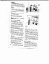
e MAXXo range of storage water heaters are designed
to work from a mains fed unvented system. An unvented kit
to regulate the cold feed is supplied with each heater and
should be installed as per Fig 1a and 1b plus drawings on
pages 8 & 9.
e temperature and pressure relief valves are supplied
factory tted for external connection to a tundish
(supplied) and suitable drain. e MAXXo can also
operate on vented systems providing the minimum water
pressure is one bar.
Expansion Vessel
Fig 1A
Fig 1B

MAXXo Water Heater
1212
CONDENSE DRAIN
Condensation is formed in the heater and this must be
continuously discharged into a drain. A trap is supplied
which should be connected into a drain via a tundish or
air break. e condense ow must not be allowed to block
otherwise the heater will fail to work correctly.
An air break is required downstream of the trap
to protect the water heater from blockages and
subsequent damage.
Each 30kW module could produce up to 3 litres of condense
per hour while at full load.
SECONDARY RETURN CIRCULATION PUMP
An additional connection for a secondary circulation is
available in the top of the heater that is located between
the hot ow and cold feed ports. We would recommend that
a non-return valve is tted in the return line.
If a secondary return circuit is tted with a secondary
pump, please ensure that the ow-rate or heat loss does
not exceed the heater maximum ow-rate or minimum
load. An excessive ow in the secondary circuit could result
in a temperature mixing effect in the heater storage vessel
resulting in a stored water temperature less than the set
temperature (see table below).
Model Type CWH30 CWH60 CWH90 CWH120
Maximum
0.9 1.8 2.7 3.6
ow rate m
3
/h
Minimum load
kW
6 12 18 24
Circulation Pump
Secondary
Return Line
Cold Water
Fig 2
SECTION 3 • INSTALLATION

MAXXo Water Heater
1313
INSTALLATION • SECTION 3
Fig 3A – Typical installation
Fig 3B – Typical installation

MAXXo Water Heater
1414
GAS SUPPLY – NATURAL GAS
e installation of the gas supply must conform, depending
on its size, to the requirements of British Standards and
Codes of Practice listed in Section 1 of this manual.
A gas meter will be connected to the service pipe by British
Gas plc or its authorised contractor.
e meter and service pipe should be checked by British
Gas or its authorised contractor to ensure that they are
adequate to deal with the gas supply to the water heater(s)
in addition to any existing or additional requirements.
Fit the service gas cock (supplied) to the gas connection on
top of the water heater using a suitable jointing compound
and connect to the gas supply.
Where the water heater(s) is(are) installed in a water
heater plant room or purpose built compartments, a
manually operated valve for the water heater house must
be tted in accordance with the Gas Safety (Installation
and Use) Regulations. e valve must be easily identied
and readily accessible.
After installation, the system should be pressure tested for
soundness and purged in accordance with BS6891 or IGE/
UP/1A or 1B as appropriate.
Please note that the minimum dynamic gas
pressure for Natural Gas must not fall below 18
mbar.
GAS SUPPLY – PROPANE
Contact your provider or supplier who will provide the
appropriate type and size of LPG supply vessel and ensure
its safe location and installation.
e installation of the gas supply must conrm to UKlpg
Code of Practice 22 - Design, Installation and Testing
of LPG piping systems, plus the requirements of British
Standards and Codes of Practice listed in Section 1 of this
manual.
Andrews Water Heaters are unregulated and a second stage
regulator must be installed to give an inlet pressure to the
appliance as follows: (see g 2)
PROPANE 37 mbar (14.86 in wg)
When using propane cylinders, connect a minimum of 47kg
cylinders as listed below, together with a manifold before
connecting to the union.
Use a minimum pipe size of ¾” bore.
Two 47kg Cylinders LCWH30 and LCWH60
ree 47kg Cylinders LCWH90
Four 47kg Cylinders LCWH120
Propane cylinders must be used and stored in
accordance with “e highly ammable liquids
and liquied petroleum gases regulations” and
should comply with UKlpg code of practice 7
“Storage of full and empty LPG cylinders and
Cartridges”.
Please note that for Propane the minimum
dynamic gas pressure to the unit must not fall
below 35 mbar.
SECTION 3 • INSTALLATION

MAXXo Water Heater
1515
INSTALLATION • SECTION 3
Important
ese drawings show a schematic representation only and should not be used for installation purposes.
Contact your gas supplier for authorised installation drawings.
Fig 4: Typical Bulk Storage Vessel Installation
Fig 5: Typical Cylinder Installation

MAXXo Water Heater
1616
ELECTRICAL SUPPLY
External wiring to the water heater(s) must be
installed in accordance with current IET Wiring
Regulations (BS 7671) for the wiring of buildings
and to any Local Regulations that may apply.
e MAXXo range is designed to operate from a
permanent 230v/50Hz single phases supply. e fuse
rating is 5 amps.
Maximum Electrical Loading
Model Type Watts Amps
30 kW 170 0.74
60 kW 340 1.48
90 kW 510 2.22
120 kW 680 2.96
e method of connection to the mains electricity
supply should facilitate complete electrical isolation
of the appliance, preferably by use of a fused double
pole switch or fused spur box serving only the heater.
e disconnection of the supply shall have a contact
separation of 3mm on all poles.
e point of connection to the mains electricity supply
should be readily accessible and adjacent to the appliance.
ELECTRICAL CONNECTION
A terminal block can be found above the control panel (Fig
4, below). is becomes accessible by rst removing the
front cover.
e following connections can be made on the terminal
block (see Fig. 5 – Wiring diagram, on next page)
Terminals Terminal Function
AL1 – AL2 Alarm volt-free contacts (24 volt 1
amp max.)
EN1 – EN2 Enable or disable contacts volt-free
(link tted to enable)*
BT1 – BT2 Secondary set point temp. enable (40
– 75°C)*
LS1 – LS2 Secondary return temp. sensor for
pasteurisation function
TH1 – TH2 Secondary pump control enable*
Pump L – Pump N Secondary pump power supply
(0.7 amp max)
*To activate, place a contact across the terminals
M5910 G
AL1
AL2
TH1
TH2
BT1
BT2
LS1
LS2
TS1
TS2
TS3
TS4
EN1
EN2
gy
gn
bk
or
y
r
y
bk
r
r/bl
bk
bk
bk
gy
br
br
br
br
gy
gy
gy
gy
br
bl
r
r
r
r
wh
wh
wh
wh
bl
br
bl
bl
bl
bl
br
br
br
br
br
br
br
br
bl
bl
bl
bl
SECONDARY PUMP
Fig 6 – Terminal block connections
SECTION 3 • INSTALLATION

MAXXo Water Heater
1717
INSTALLATION • SECTION 3
master
230V/50Hz
br wh
br
br
br
wh
wh
gr
gr
gr
gr
r
r
r
r
wh
comm. 2
comm. 3
comm. 4
comm. 1
y
gy
r
br
bl
br bl
r r
bl
wh
bk
bl
br
bl
y
or
y
br
gy
br
bl
br gy
br
bl
gy
bk
y
AL1
AL2
TS1
TS2
TS3
TS4
br
bl
br
bl
br
br
br
bl
bl
bl
br
br
br
bl
bl
bl
gy
gn
bk
or
y
r
y
bk
r
bk
gr
or
AL1-AL2 = Alarm
BT1-BT2 = Activate Second Setpoint
TH1-TH2 = Activate Secondary Pump
LS1-LS2 = Secondary Sensor
TS1-TS2 = Tank sensor, low position
EN1-EN2 = enable / disable
bl = blue
br = brown
y = yello w
gn = green
gy = grey
or = orange
br
bl
BT1
BT2
LS1
LS2
TH1
TH2
L N
br
bl
br bl
br
r = red
wh = white
bk = black
pi = pink
bl
bk
pi
or
flow sensor 2
flow sensor 1
return sensor
slave 1
fan
ionisation rod
gasvalve
primary
pump
glow plug
tank sensor, low position
mains 1
mains 2
mains 3
mains 4
pump
pump L
secondary
pump
pump N
M5879D
wh
(Max 24 V 1.0 Amp)
E
g/y
g/y = green & yellow
EN1
EN2
tank sensor, high position
TS3-TS4 = Tank sensor, high position
r/bl
bk
gy
r/bl
r
bk
}
gn
Fig. 7 – Wiring Diagram
Make sure that the phase (L) and the neutral (N) are connected to the correct terminals on the connector. e appliance is
phase sensitive therefore swapping the phase and neutral will lead to a fault in the appliance.

MAXXo Water Heater
1818
TEMPORARY WATER HEATER TEMPERATURE
CHANGE
It is possible to change the water heater temperature
remotely via a timer programme. First of all, the new
desired water heater temperature is set at a value higher
or lower than the water heater temperature during normal
operation. is makes it possible, for example, to carry out
Legionella ushing. (See page 32).
e water heater temperature changes when the contacts
connected to terminals BT1 – BT2 are closed. e water
heater temperature goes back to normal operation when
these contacts are opened again.
If the temperature change is used for Legionella ushing,
it is possible to return the water heater temperature to
normal operation before the timer programme nishes.
is happens on the basis of a temperature measurement,
for example at the end of a circulation line (secondary
return). For this purpose, a 10K NTC temperature sensor
(part number E674) must be connected to the terminals
LS1 – LS2. e water heater temperature now goes back
to normal operation if the temperature is higher at the
measuring point than the secondary pre-set water heater
temperature minus 5°C for 20 minutes.
If, for example, the secondary pre-set water heater
temperature is set at 70°C, the water heater temperature
returns back to normal operation as soon as the
temperature at the secondary measuring point has been
above 65°C for more than 20 minutes.
CIRCULATION PUMP AND STORAGE TANKS
A circulation pump (maximum 0.7 A) can be connected at
the terminal pump L – pump N. e circulation pump can
then be controlled by a thermostat connected to terminals
TH1-TH2. Connecting the contacts of the thermostat then
activates the circulation pump.
e application can be used when the water heater is
combined with a separate storage tank.
As soon as the temperature in the tank gets too low, the
thermostat will activate the pump so the tank is heated
up again. Matching MAXXo storage tanks are available in
200 and 300 litre sizes, models HWST200 and HWST300.
ese tanks are tted with a thermostat for use as above.
See below for schematic system design and pages 16 & 18
for tank dimensions and wiring diagram.
FIG 8 – SCHEMATIC SYSTEM DESIGN
SECTION 3 • INSTALLATION

MAXXo Water Heater
1919
INSTALLATION • SECTION 3
Fig 9 – HWST Tank Dimensions
Fig 10 – Wiring Diagram
1
1
/2" Hot
water
supply
1" Return
1
1
/2" Feed from
water heater
Tank inspection hatch
28 mm T&P outlets
1 or 2 Tundishes supplied
PLAN VIEW
47
T&P outlets
Thermostat
153
153
Drain access
28 mm valve
602 602
1528 (200 litre t ank)
1952 (300 litre t ank)
HWST 200 HWST 300 STORAGE TANKS

MAXXo Water Heater
2020
FLUE SYSTEMS
e versatile ueing options will provide a solution to most
ushing requirements. e heater, when tted with
a concentric ue system, provides a room sealed
application. e concentric ue, supplied by Andrews,
is available for either horizontal or vertical installation
and the table below shows the basic kit supplied plus
optional extras. Alternatively, the heater can be tted with
a conventional ue system, which can be obtained from
a specialist ue stockist. A ue system suitable for a
condensing pressurised system must be specied.
e table and the concentric ue component below show
the maximum allowable length of ue for both systems.
e following pages show standard kits and additional
items for concentric ue supplied by Andrews. Horizontal
and vertical ue kits must be ordered separately. Flue kits
are not included in the heater price.
e ue system must be properly installed. Ensure
the inner ue is securely sealed at all the joints
otherwise incomplete combustion may result.
Do not exceed maximum ue lengths including
elbows.
GENERAL
Flue terminals must be installed in accordance with
BS 5440 and IGE/UP/10 to ensure the products of
combustion are properly dispersed. e drawing on page
27 shows minimum clearances for the ue terminals.
e ue terminal should be positioned where it will not
cause a nuisance from noise or from the combustion
products accumulating. Please contact Andrews technical
department if advice is needed for a particular installation.
See drawings on page 26.
We recommend that a condensate trap be tted when the
secondary ue length is over 1.5m.
If installed in a roof valley, the terminal should be at least
1m above the highest part of the roof structure and 2.5m
from any adjacent structure. e terminal must be tted
with a guard if less than 2m above ground level or in a
position where it may cause injury to persons resulting
from touching a hot surface. Guards can be ordered with
ue components. See table on pages 20 and 23.
Model CWH30 CWH60 CWH90 CWH120
Flue size (concentric)
mm 80/125 80/125 130/200 130/200
Max. ue run – concentric (a)
m 14 12 14 14
Max. ue run – conventional (b)
m 50 20 50 40
Max. ue static pressure
Pa 140 140 140 140
Max. ue gas volume
m
3
/h 41 82 123 164
Max. ue gas temperature
°C 52 52 52 52
(a) For a concentric ue/room sealed, reduce ue length by 1.2m for 90° bend, 0.7m for 45° bend and 1.5m
for condense trap.
(b) For a conventional ue, reduce ue length by 4m for 90° bend, 2m for 45° bend and 4 m for condense trap.
e different ventilation requirements for room sealed or conventional ue systems are given on pages 28 – 30.
SECTION 3 • INSTALLATION
/