
Operator's Manual
Front Tine Tiller
Model Series
300 & 330
IMPORTANT: Read safety rules and instructions carefully before operating equipment.
Warning: This unit is equipped with an internal combustion engine and should not be used on or near any unimproved forest-covered, brush-
covered or grass-covered land unless the engine's exhaust system is equipped with a spark arrester meeting applicable local or state laws (if
any). If a spark arrester is used, it should be maintained in effective working order by the operator. In the State of California the above is required
by law (Section 4442 of the California Public Resources Code). Other states may have similar laws. Federal laws apply on federal lands. A spark
arrester for the muffler is available through your nearest engine authorized service dealer or contact the service department, P.O. Box 361131
Cleveland, Ohio 44136-9722.
MTDLLC, P.O.BOX361131CLEVELAND,OHIO44136-9722
PRINTED IN U.S.A. FORM NO. 770-10564E
(11/30/2004)

Content
ImportantSafeOperationPractices
AssemblingYourTiller
KnowYourTiller
OperatingYourTiller
MakingAdjustments
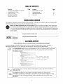
TABLEOFCONTENTS
Page Content Page
3 Maintaining You rTiller 10
5 Troubleshooting 11
6 Illustrated Parts List 12
7 Warranty 16
9
FINDINGMODELNUMBER
This Operator's Manual is an important part of your new tiller. Itwill help you assemble, prepare and maintain the
unit for best performance. Please read and understand what it says.
Before you start assembling your new equipment, please locate the model plate on the equipment
and copy the information from it in the space provided below. A sample model plate is also given below.
You can locate the model plate by looking at the rear of the tine shield. This information will be necessary
to use the manufacturer's web site and/or help from the Customer Support Department or an authoriJed
service dealer.
" -_ Copy the model number here:
MT,D _ P._TDo._OXLL_'3_3_] Copy the serial number here:
CLEVELAND,OH 44136
330_220-4683
www.mtdproducts.com 8_Q-8_O-731Q
CUSTOMERSUPPORT
PleasedoNOTretum theunit totheretailer without first contactingCustomerSupport.
If you have difficulty assembling this product or have any questions regarding the controls, operation or
maintenance of this unit, you can seek help from the experts. Choose from the options below:
Visit mtdproducts.com for many useful suggestions. Click on Customer Support button andyou will get the four options reproduced here. Click on the appropriate button and help is
immediately available.
\En ine
v
EAn_dAnswers
The answe_ _ you am
_lle_lif_ yeIH i_l _ll[_ies e[ _[ _81e yell _e_$e_a_
a mouse_c#ck away!
_ice gooato[
If you prefer to reach a Customer Support Representative, please call (330) 220-4MTD or
1(800) 800-7310.
The engine manufacturer is responsible for all engine-related issues with regard to
performance, power-rating, specifications, warranty and service. Please refer to the engine
manufacturer's Owner's/Operator's Manual, packed separately with your unit, for more
information.

SECTION1: IMPORTANTSAFEOPERATIONPRACTICES
WARNING: This symbol points out important safety instructions which, if not followed, could
endanger the personal safety and/or property of yourself and others, Read and follow all instructions in
this manual before attempting to operate this machine, Failure to comply with these instructions may
result in personal injury, When you see this symbol-- heed its warning,
WARNING: Engine exhaust, some of its constituents, and certain vehicle components contain or
emit chemicals known to State of California to cause cancer and birth defects or other reproductive
harm.
DANGER: This machine was built to be operated according to the rules for safe operation in this
manual, As with any type of power equipment, carelessness or error on the part of the operator can
result in serious injury, This machine is capable of amputating hands and feet. Failure to observe the
following safety instructions could result in serious injury or death,
Training
1, Read, understand, and follow all instructions on the
machine and in the manual(s) before attempting to
assemble and operate. Keep this manual in a safe
place for future and regular reference and for
ordering replacement parts,
2, Be familiar with all controls and their proper
operation. Know how to stop the machine and
disengage them quickly.
3. Never allow children under 14years old to operate
this machine, Children 14years old and over should
read and understand the operation instructions and
safety rules in this manual and should be trained
and supervised by a parent,
4. Never allow adults to operate this machine without
proper instruction,
5. Keep bystanders, helpers, pets and children at least
75 feet from the machine while it is in operation,
Stop machine if anyone enters the area.
Preparation
1, Thoroughly inspect the areawhere the equipment is
to beused, Remove all stones, sticks, wire, and
other foreign objects which could be tripped over
and cause personal injury,
2, Wear sturdy, rough-soled work shoes and close
fitting slacks and shirt. Loose fitting clothes or
jewelry can becaught in movable parts, Never
operate this machine in bare feet or sandals,
3, Disengage clutch levers and shift (if provided) into
neutral CN") before starting the engine.
4, Never leave this machine unattended with the
engine running.
5, Never attempt to make any adjustments while
engine is running, except where specifically
recommended in the operator's manual,
6, To avoid personal injury or property damage use
extreme care in handling gasoline, Gasoline is
extremely flammable and the vapors are explosive,
Serious personal injury can occur when gasoline is
spilled on yourself or your clothes which can ignite,
Wash your skin and change clothes immediately,
7, Use only anapproved gasoline container,
8, Extinguish all cigarettes, cigars, pipes and other
sources of ignition,
9, Never fuel machine indoors.
10, Never remove gas cap or add fuel while the engine
is hot or running.
11, Allow engine to cool at least two minutes before
refueling,
12, Never over fill fuel tank. Fill tank to nomore than 1/2
inch below bottom of filler neck to provide space for
fuel expansion.
13, Replace gasoline cap and tighten securely,
14, Ifgasoline is spilled, wipe it off the engine and
equipment, Move machine to another area. Wait 5
minutes before starting the engine.
15, Never store the machine or fuel container inside
near an open flame, spark or pilot light (e.g,
furnace, water or space heater, clothes dryer etc,),
16, Allow machine to cool 5 minutes before storing,
Operation
1. Donot put hands or feet near rotating parts. Contact
with the rotating parts can amputate hands and feet.
2. Do not operate machine while under the influence
of alcohol or drugs.
3, Never operate this machine without good visibility
or light. Always be sure of your footing and keep a
firm hold on the handles.
4, Keep bystanders, helpers, pets, and children at
least 75 feet from the machine while it is in
operation, Stop the machine if anyone enters the
area,
5, Be careful when tilling in hard ground, The tines
may catch in the ground and propel the tiller
forward, If this occurs, let go of the handle bars and
do not restrain the machine.
6. Exercise extreme caution when operating on or
crossing gravel surfaces, Stay alert for hidden
hazards or traffic, Do not carry passengers,
7. Never operate the machine at high transport
speeds on hard or slippery surfaces,
8. Exercise caution to avoid slipping or falling,

9, Lookdownandbehindandusecarewhenin
reverseorpullingmachinetowardsyou,
10, Starttheengineaccordingtotheinstructionsfound
inthismanualandkeepfeetwellawayfromthe
tinesatalltimes,
11, Afterstrikingaforeignobject,stoptheengine,
disconnectthesparkplugwireandgroundagainst
theengine,Thoroughlyinspectthemachineforany
damage,Repairthedamagebeforestartingand
operating,
12, Disengageallclutchleversandstopenginebefore
youleavetheoperatingposition(behindthe
handles),Waituntilthetinescometoacomplete
stopbeforeuncloggingthetines,makingany
adjustments,orinspections.
13, Neverrunanengineindoorsorinapoorly
ventilatedarea.Engineexhaustcontainscarbon
monoxide,anodorlessanddeadlygas.
14, Mufflerandenginebecomehotandcancausea
burn.Donottouch,
15, Usecautionwhentillingnearfences,buildingsand
undergroundutilities,Rotatingtinescancause
propertydamageorpersonalinjury.
16, Donotoverloadmachinecapacitybyattemptingto
tillsoiltodeepattofastofarate.
17, Ifthemachineshouldstartmakinganunusualnoise
orvibration,stoptheengine,disconnectthespark
plugwireandgrounditagainsttheengine.Inspect
thoroughlyfordamage,Repairanydamagebefore
startingandoperating,
18, Keepallshields,guardsandsafetydevicesinplace
andoperatingproperly.
19, Neverpickuporcarrymachinewhiletheengineis
running,
20, Useonlyattachmentsandaccessoriesapprovedby
themanufacturer.Failuretodoso,canresultin
personalinjury.
21, Ifsituationsoccurwhicharenotcoveredinthis
manual,usecareandgoodjudgment.Contactyour
dealerortelephone1-800-800-7310forassistance
andthenameofyournearestservicingdealer.
Maintenance& Storage
1. Never tamper with safety devices, Check their
proper operation regularly.
2. Check bolts and screws for proper tightness at
frequent intervals to keep the machine in safe
working condition, Also, visually inspect machine for
any damage,
3. Before cleaning, repairing, or inspecting, stop the
engine and make certain the tines and all moving
parts have stopped, Disconnect the spark plug wire
and ground it against the engine to prevent
unintended starting.
4, Do not change the engine governor settings or over-
speed the engine, The governor controls the
maximum safe operating speed of the engine,
5, Maintain or replace safety and instruction labels, as
necessary,
6, Follow this manual for safe loading, unloading,
transporting, and storage of this machine.
7, Never store the machine or fuel container inside
where there is an open flame, spark or pilot light
such as a water heater, furnace, clothes dryer etc,
8, Always refer to the operator's manual for proper
instructions on off-season storage,
9, If the fuel tank has to be drained, do this outdoors,
10, Observe proper disposal laws and regulations for
gas, oil, etc. to protect the environment.
YourResponsibility
1. Restrict the use of this power machine to persons
who read, understand and follow the warnings and
instructions in this manual and on the machine.
2. The safety label on the tiller is reproduced below for
your review. To ensure safe operation of the tiller,
follow the instructions on all labels closely,
TO AVOID SERIOUS INJURY
READTHEOPERATOR'SMANUAL.
KNOWLOCATIONANDFUNCTIONS
OFALLCONTROLS.
KEEPALLSAFETYDEVICESAND
SHIELDSINPLACEANDWORKING.
NEVERALLOWCHILDRENOR
UNINSTRUCTEDADULTSTO
OPERATETILLER.
SHUTOFFENGINEBEFORE
UNCLOGGINGTINESORMAKING
REPAIRS.
KEEPBYSTANDERSAWAYFROM
MACHINE.
KEEPAWAYFROMROTATING
PARTS.
USEEXTREMECAUTIONWHEN
REVERSINGORPULLINGTHE
MACHINETOWARDSYOU.
, S30159

SECTION2: ASSEMBLINGYOURTILLER
NOTE: This operator's manual covers various models
of riflers. The units illustrated may vary slightly from
your unit. Follow only those instructions which pertain
to your model number.
NOTE: References to right or left side of the tiller are
determined from behind the unit in the operating
position.
IMPORTANT:This unit is shipped without gasoline or oil
in the engine. Be certain to service engine with gasoline
and oil as instructed in the separate engine manual
before operating your machine.
LoosePartsInCarton
Tailpiece and Depth Stake
NOTE: All hardware needed for assembly is attached
to the loose parts or the tiller.
BeforeAssembly
WARNING: Disconnect the spark plug wireand ground it against the engine to prevent
unintended starting.
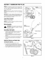
AssemblingTheHandle
• Remove the handle adjustment lever from handle
and lift up upper handle to raise in operating
position. See Figure 1.
• Reinsert adjustment lever through the lower hole,
tightening the lever into lock nut on the retainer
bracket.
• Once the lever is in the lock nut, the handle can be
moved to the desired position and then tighten
securely.
Handle
Adjustment Lever
\
\
\
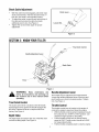
AttachingTailpieceandDepthStake
ToolsRequiredForAssembly
(1) 1/2" socket wrench (or adjustable wrench)
• Remove the two self-tapping screws on the frame
and slide the tailpiece into the frame, with the lower
hole in the tailpiece toward the front. See Figure 2.
• Secure tailpiece with the screws just removed.
Tailpiece
Figure 1
Self-Tapping
Screws
Handle
Adjustment Lever
-Retainer Bracket
Figure 2

CheckCableAdjustment
• With the clutch lever disengaged, pull starter rope
slowly several times. The tines should not turn. If
they turn, the cable is not adjusted properly.
• To adjust the cable, loosen the nut near the top of
the cable and unscrew the cable to provide
additional slack in wire. See Figure 3.
• Tighten the nut and check again for proper
adjustment.
Clutch Lever_.__
Loosen Nut
Figure 3
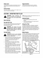
SECTION3: KNOWYOURTILLER
Tine Clutch Control
Handle Adjustment Lever
Depth Stake
Tines
Figure 4
WARNING: Read, understand, and
follow all instructions and warnings on
the machine and in this manual before
operating.
Tine ClutchControl
The clutch control lever is located on the left handle.
Squeezing the lever against the handle engages the
tine drive. Release the lever to stop the tines from
turning. See Figure 4.
DepthStake
The depth stake is located in the rear of the tiller and it
controls the tilling depth. See Figure 4.
HandleAdjustmentLever
The handle may be adjusted to the height desired.
Loosen the handle adjustment lever a few turns and
pivot handle up or down to desired position. Tighten
lock. See Figure 4.
ThrottleControl
The throttle control lever islocated on the engine. It
controlsthe engine's speed and stops the engine.
• With the throttle control pushed completely forward,
the carburetor isin START or FAST position. Use
maximum engine speed for deep tilling.
• Pull the throttle control back to reduce engine
speed to IDLE. Throttle control should be at IDLE
for transporting the tiller.
• Pull the throttle completely back to stop the engine.

ChokeLever
The choke lever is located near the throttle control. It is
used to enrich the fuel mixture when starting a cold
engine.
StarterHandle
The starter handle is located on the engine and is
used to manually start the engine.
EngineControls
See the separate engine manual for additional
information and functions of the engine controls.
SECTION4: OPERATINGYOURTILLER
WARNING: Read, understand, and
follow all instructions and warnings on
the machine and in this manual before
operating.
BeforeStarting
GasAndOilFill-Up
Service the engine with gasoline and oil as instructed in
the separate engine manual packed with your tiller.
Read instructions carefully.
l_ WARNING: Use extreme care when
handling gasoline. Gasoline is extremely
flammable and the vapors are explosive.
Never fuel machine indoors or while the
engine is hot or running.
NOTE: See your engine manual packed with your unit
for more detailed instructions.
StoppingEngine
• Move throttle control lever to STOP or OFF
position.
• Disconnect spark plug wire from spark plug and
ground against the engine.
UsingYourTiller
Your tiller (also known as a cultivator) is a precision
built machine designed for seed bed preparation,
cultivating, furrowing and mulching. It is engineered to
minimize the hardest work in the vegetable or flower
garden, to till the soil for planting and cultivating, and to
perform many other useful labor saving tasks in the
garden.
StartingEngine
_ WARNING: Be sure no one is standing
in front of the tiller while the engine is
running or being started.
• Attach spark plug wire to spark plug. Make sure the
metal cap on the end of the spark plug is fastened
securely over the metal tip on the spark plug.
• Make sure that the tine clutch control is
disengaged.
• Place the throttle control in the FAST position.
• Move choke lever to CHOKE position. A warm
engine requires little or no choke.
• Grasp starter handle and pull rope out slowly until
engine reaches start of compression cycle (rope
will pull slightly harder at this point). Let the rope
rewind slowly.
• Pull rope with a rapid, continuous, full arm stroke.
Keep a firm grip on starter handle. Let rope rewind
slowly. Do not let starter handle snap back against
starter. Repeat until engine starts.
• When engine starts, move choke lever on engine
halfway between CHOKE and RUN. As the engine
warms up, move the lever to RUN position.
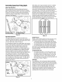
WheelPosition
The tiller is shipped with the wheels adjusted such that
the unit sits level. While tilling, as the tines enter the
ground and the front of the tiller lowers, the wheels
must be raised to level the unit, which is essential for
proper engine operation. This adjustment is made by
removing the clevis pin and hairpin clip from wheel
yoke, raising the wheels to the desired height, and
replacing the clevis pin and hairpin clip. See Figure 5.
Stake
Hairpi_
& Clevis Pins
Figure 5

ControllingSpeedAndTillingDepth
WheelYokeAdjustment
Place wheel yoke so that the wheels are forward
(nearest point between wheels and tines) for shallow
tilling, cultivating and transport. The forward speed will
increase. Turn yoke around (farthest point between
wheels and tines) for deep tilling. Forward speed will
decrease. See Figure 6.
Yoke _ition Wheel
For Deep Tilling ForShallow Tilling
Figure 6
DepthStakeAdjustment
The depth stake acts as a brake for the tiller and
controls the depth and speed at which the machine will
operate. Remove the clevis pin and hairpin clip to raise
or lower depth stake. Refer to Figure 5.
By increasing the depth of the depth stake, the forward
speed of the machine is reduced and the working depth
is increased. When the depth stake is raised, the
working depth of the machine is reduced and the
forward speed is increased. The working depth of the
machine may be predetermined by setting the depth
stake and wheels so that the wheels are about four
inches from the ground when the tines and depth stake
are resting on the ground. This setting will permit a
working depth of about four inches. When presetting
the working depth, the handles should be adjusted so
the hand grips are a little above waist. The tiller will be
lower when the tines and depth stake penetrate the
ground. See Figure 7.
Transport De
Position
Shallow
Tilling S
Deep
Deep Tilling
Figure 7
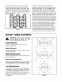
When tilling, leave approximately 8 inches of untilled
soil between the first and second tilling paths, then
make the third path between the first and second. In
some soils, the desired depth is obtained the first time
over the garden. In other soils, the desired depth is
obtained by going over the garden two or three times. In
the latter case, the depth stake should be lowered
before each succeeding pass over the garden. Passes
should be made across the length and width of the
garden alternately. Rocks which are turned up should
be removed from the garden area. See Figure 8.
Figure 8
HandlePressure
Further control of tilling depth and travel speed can be
obtained by variation of pressure on the handles.
• A downward pressure on the handles will reduce
the working depth and increase the forward speed.
• An upward pressure on the handles will increase
the working depth and reduce the forward speed.
The type of soil and working conditions will determine
the actual setting of the depth stake and the handle
pressure required.
TransportingtheTiller
• To transport the tiller to or from the garden, pivot
the depth stake forward and out of the way. With
the throttle control in SLOW position, the unit will
walk freely on the lawn. If the operator does not
allow the tiller to move freely, the unit will start to till
the surface. Refer to Figure 7.
Cultivating
For cultivating, a two to three inch depth is desirable.
Setting the wheels and depth stake so that the wheels
are about two inches above the ground while the tiller is
resting on the tines and depth stake will allow the
machine to work at cultivating depth. The throttle
should be set to control forward movement to a slow
walking speed. With the outer tines installed, the
working width of the machine is 22 or24 inches.

Forcultivation,thismaybereducedto13inchesby
removingtheoutertines.RefertotheAdjustment
Section.Whenlayingoutplantrows,besuretoallow
enoughwidthtopermitcultivationbetweentherows.In
growingcornorsimilarcrops,check-rowplantingwill
permitcrosscultivationandpracticallyeliminatehand
hoeing.SeeFigure9.
Figure 9
The tiller has many uses other than tilling and
cultivating a garden. One of these is the preparation of
lawn area for seeding. The tiller will prepare a deep
seed bed which will be free of hard untilled spots,
allowing a better stand of grass to grow. The tiller is
very useful for loosening hard soil for excavation with a
shovel. No tedious handwork will be necessary. Your
tiller may be used for mixing compost in the pile, or for
mixing it with the soil in your garden. This should be
done after the soil has been broken to the full working
depth. The compost should be worked in to a depth of
six to seven inches. This may be done by working the
length of the garden and then by making separate
passes across its width. The addition of decayed
organic matter will substantially increase the fertility of
your garden. For proper decaying action, fertilizer
should be applied and worked in with the mulch
materials. Breaking up leaves and straw and mixing it
with several inches of soil causes the soil to hold
moisture longer and allows proper aeration of the plant
root system. This also retards the growth of weeds.
SECTION5: MAKINGADJUSTMENTS
WARNING: Disconnect the spark plugwire and ground it against the engine
before performing any adjustments.
EngineAdjustment
Refer to the separate engine manual for engine
adjustment instructions.
WheelAdjustment
To adjust the wheel yoke and wheel position, refer to
the Operating Section.
DepthStakeAdjustment
To adjust the depth stake to a desired position, refer to
the Operating Section.
ClutchControlAdjustment
Periodic adjustment of the belt tension may be required
due to normal stretch and wear on the belt. To adjust
the clutch control lever, refer to the Assembly Section.
TineWidthAdjustment
The tilling width of the unit is22 inches. Tilling width can
be increased to 24 inches by removing the clevis pins
and hairpin clips, sliding the outer tines out one inch,
and securing in this position with the clevis pins and
hairpin clips. For cultivation, reduce the tine width to 13
inches by removing the outer tines completely.
See Figure 10.
24"
13"
Figure 10

SECTION6: MAINTAININGYOURTILLER
WARNING: Disconnect the spark plug
wire and ground it against the engine
before performing any repairs or
maintenance.
Engine
Refer to the separate engine manual for engine
maintenance instructions.
Maintain engine oil as instructed in the separate
engine manual packed with your unit. Read and follow
instructions carefully.
Service air cleaner every ten hours under normal
conditions. Clean every hour under extremely dusty
conditions. Poor engine performance and flooding
usually indicates that the air cleaner should be
serviced. To service the air cleaner, refer to the
separate engine manual packed with your unit.
IMPORTANT: Never run your engine without air cleaner
completely assembled.
The spark plug should be cleaned and the gap reset
every 25 hours of engine operation. Spark plug
replacement is recommended at the start of each tiller
season; check engine manual for correct plug type and
gap specification.
Clean the engine regularly with a cloth or brush. Keep
the cooling system (blower housing area) clean to
permit proper air circulation which is essential to engine
performance and life. Be certain to remove all dirt and
combustible debris from muffler area.
Lubrication
Transmission
The transmission is pre-lubricated and sealed at the
factory. It requires no checking. See an authorized
service dealer for any service issues.
ClutchHandle
Lubricate the pivot point on the clutch handle and the
cable at least once a season with light oil. The control
must operate freely in both directions.
Pivot Points
Lubricate all pivot points and linkages at least once a
season with light oil.
TineShafts
Remove tine assemblies and lubricate the tine shafts at
least once a season.
WheelShafts
Remove wheel assemblies and lubricate the axle shafts
at least once a season.
CleaningTineArea
Clean the underside of the tine shield after each use.
The dirt washes off the tines easier if rinsed off
immediately instead of after it dries. Always towel dry
the tiller afterwards and apply a light coat of oil or
silicone to prevent rusting or water damage.
IMPORTANT:Never use a "pressure washer" to clean
your tiller. Water can penetrate tight areas of the tiller
and its chain case and cause serious damage to the
unit.
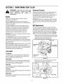
BeltReplacement
Your tiller has been engineered with a belt made of
special material for longer life and better performance.
It should not be replaced with an off-the-shelf belt. See
the retailer from which you purchased your tiller, an
authorized MTD Service Dealer or phone 1-800-800-
7310 for information regarding price and availability.
• Remove the two hex washer screws from the front
of the belt cover and remove the lock nut and flat
washer from the side of the belt cover.
Remove the belt cover. See Figure 11.
Belt Cover
Hex Washel
Screw
Lock Nut &
"Flat Washer
Screw
Figure 11
Remove the hex screw and idler pulley from the
idler bracket assembly. See Figure 12.
Hex Screw
Pulley
Figure 12
lO

• Reassemble the new belt and reattach idler pulley
to secure in place.
• Replace belt cover assembly and secure with the
hardware removed earlier.
Off-SeasonStorage
If the tiller will not be used for a period longer than 30
days, the following steps should be taken to prepare the
tiller for storage.
• Clean the exterior of engine and the entire tiller
thoroughly. Lubricate the tiller as described in the
lubrication instructions.
• We do not recommend the use of pressure
washers to clean your unit. They may cause
damage to spindles, pulleys, bearings or the
engine. The use of pressure washers will result in
shortened life and reduce serviceability.
• Refer to the engine manual for correct engine
storage instructions.
• Wipe tines with oiled rag to prevent rust.
• Store tiller in a clean, dry area. Do not store next to
corrosive materials, such as fertilizer.
NOTE: When storing any type of power equipment in
an unventilated or metal storage shed, care should be
taken to rustproof the equipment. Using a light oil or
silicone, coat the equipment and especially any
springs, bearings, and cables.
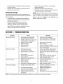
SECTION7: TROUBLESHOOTING
Problem Cause
Engine fails to start
Engine runs erratic
Engine overheats
Tines do not engage
1. Spark plug wire disconnected.
2. Fuel tank empty or stale fuel.
3. Throttle control lever not in correct
starting position. (If equipped)
4. Choke not in ON position.
5. Blocked fuel line.
6. Faulty spark plug.
7. Engine flooded
1. Spark plug wire loose.
2. Unit running on CHOKE.
3. Blocked fuel line or stale fuel.
4. Vent plugged.
5. Water or dirt in fuel system.
6. Dirty air cleaner.
7. Carburetor out of adjustment.
1. Engine oil level low.
2. Dirty air cleaner.
3. Air flow restricted.
4. Carburetor not adjusted properly.
1. Foreign object lodged in tines.
2. Tineclevis pin(s) missing.
3. Control cable not adjusted properly.
4. Belt worn and/or stretched.
5. Pulley and idler not in correct
adjustment.
Remedy
1. Connect wire to spark plug.
2. Fill tank with clean, fresh gasoline.
3. Move throttle lever to start position.
4. Move lever to ON position.
5. Clean fuel line.
6. Clean, adjust gap, or replace.
7. Wait a few minutes to restart, but do not
prime. (If Equipped)
1. Connect and tighten spark plug wire.
2. Move choke lever to OFF position.
3. Clean fuel line; fill tank with clean, fresh
gasoline.
4. Clear vent.
5. Drain fuel tank. Refill with fresh fuel.
6. Clean following engine manual.
7. Refer to engine manual.
1. Fill crankcase with proper oil.
2. Clean air cleaner.
3. Remove blower housing and clean.
4. Refer to engine manual.
1. Stop tiller completely, check and
discard foreign object.
2. Replace tineclevis pin(s).
3. Adjust control cable.
4. Replace belt.
5. Take unit to authorized service dealer.
NOTE: For repairs beyond the minor adjustments listed above, contact your nearest service dealer.
11

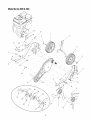
SECTION8: MODELSERIES300 & 330 PARTSLIST
1'4
27 17
19
18
\14
24
42
-5
14
45
51
61
.63
_52
53 _54
_55
56
\\
\,,
57
12

ModelSeries300 &330
Ref.
Part No.
No.
1. 720-0274
2. 731-0473
3. 686-0002
4. 649-0137
5. 712-0442
6. 738-1225
7. 746-1148
8. 738-1226
9. 710-0189
10. 736-0242
11. 786-0340
12. 710-0606
13. 719-0279
14. 712-0720
15. 786-0341
16. 649-0136
17. 710-0805
18. 711-0415
19. 750-0890
20. 786-0003
21. 786-0004
22. 786-0005
23. 714-0149B
24. 712-3004A
27. 710-0604A
28. 710-0602
29. 738-0934
30. 712-0240
31. 736-0171
32. 786-0138A
33. 786-0139A
Part Description
Grip
Clutch Grip
Clutch Lever
Handle Assembly
Lock Nut Cap 1/4-20
Shoulder Screw
Clutch Cable
Shoulder Screw
Hex Cap Screw 5/16-18 x 3.0
Bell Washer.340 ID x.872 OD
Adjustable Handle Crank
Hex Cap Screw 1/4-20 x 1.5
Rope Guide
Flange Nut 5/16-18
Retainer Bracket
Handle Tube
Hex Cap Screw 5/16-18 x 1.5
Clevis Pin 3/8 x 1.62
Spacer
Tailpiece Bracket LH
Tailpiece Bracket RH
Depth Bar
Cotter Pin
Hex Flange Locknut 5/16-18
Hex Washer Screw 5/16-18 x.625
Hex Washer Screw 5/16-18 x 1.0
Ref.
Part No.
No.
35. 711-0919
37. 786-0035A
38. 710-0502A
39. 710-3008
40. 786-0053
42. 786-0039B
43. 736-0119
44. 710-0107
45. 750-0892
46. 748-0350
47. 756-0971
48. 756-0972
49. 754-0428
50. 736-0452
51. 710-0152
52. 756-0585
53. 736-0312
54. 736-0112
55. 712-3029
56. 710-0599
57. 786-0056
58. 712-0392
59. 736-3020
60. 738-0930
61. 712-0266
62. 786-0144
Part Description
Belt Cover Bolt
Tine Shield 20"
Hex Washer Screw 3/8-16 x 1.25
Hex Cap Screw 5/16-18
Tine Shield Bracket 20"
Cover Bracket
Lock Washer 5/16
Hex Cap Screw 5/16-24 x.50
Input Spacer.64 ID x 2.4 Lg
Pulley Adapter
Engine Inner Half Pulley
Engine Outer Half Pulley
Belt
Bell Washer.396 ID x 1.140 OD
Hex Cap Screw 3/8-24 x 1.0
Flat Pulley
Retainer Bearing Washer
Spherical Washer.531 ID x.620 OD
Jam Nut 1/2-20
Hex Washer Screw 1/4-20 x.50
Belt Cover
Cap Lock Nut 1/4-28
Flat Washer.271 ID x.630 OD
Shoulder Screw
Jam Nut 3/8-16
Idler Bracket
Shoulder Screw
Jam Nut 7/16-20
Lock Washer 7/16
Frame RH
Frame LH
63. 786-0149
64. 756-0313
65. 710-0723
66. 686-0088
Idler Belt Keeper
Flat Idler
Hex Cap Screw 3/8-16 x 1.25
Idler Bracket Assembly
13

ModelSeries300 &330
21
<
17
4
16
5
14
14

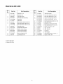
ModelSeries300 &330
Ref.
No.
1.
2.
3.
4.
5.
6.
7.
8.
9.
10.
11.
12.
13.
Part No.
734-1988
734-17815
738-0929
686-0081A
714-0149B
711-0415
736-0242
710-0189t
710-01765
738-0934
786-0145A
750-0470
686-0189t
686-0091_
712-0429
736-0171
Part Description
Wheel 8 x 1.75
Wheel 8 x 1.8
Shoulder Screw
Wheel Bracket Assembly
Cotter Pin
Clevis Pin
Bell Washer.340 ID x.872 OD
Hex Cap Screw 5/16-18 x 3.0
Hex Cap Screw 5/16-18 x 2.75
Shoulder Screw
Engine Mounting Plate
Spacer.47 OD x.96Lg
Chain Case Assembly
Chain Case Assembly
Hex Lock Nut 5/16-18
Lock Washer 7/16
Ref.
Part No.
No.
14. 712-0240
15. 642-0002:1:
642-0003:1:
16. 642-0004:1:
642-0005:1:
17. 710-0502A
18. 712-3010
19. 736-0242
20. 710-3180
21. 750-02731-
22. 049221-
23. 049231-
24. 711-07021-
25. 049181-
26. 710-05991-
27. 750-04561-
Part Description
Jam Nut 7/16-20
Inner Tine Assembly - RH 12"
Inner Tine Assembly - LH 12"
Outer Tine Assembly -RH 12"
Outer Tine Assembly - LH 12"
Hex Washer Screw 3/8-16 x 1.25
Hex Nut 5/16-18
Bell Washer.340 ID x.872 OD
Hex Cap Screw 5/16-18 x 1.75
Spacer, .51 x .69 x 1.97
Tine 9.5" RH
Tine 9.5" LH
Clevis Pin
Tine Adapter
Self-tapping Screw, 1/4-20 x .5
Spacer, .790 x .347
1 Series 300 Only
:1:Series 330 Only
15

MANUFACTURER'S LIMITED WARRANTY FOR:
The limited warranty set forth below is given by MTD LLC with
respect to new merchandise purchased and used in the
United States, its possessions and territories.
"MTD'warrants this product against defects in material and
workmanship for a period of two (2) years commencing on the
date of original purchase and will, at its option, repair or
replace, free of charge, any part found to be defective in
materials or workmanship. This limited warranty shall only
apply if this product has been operated and maintained in
accordance with the Operator's Manual furnished with the
product, and has not been subject to misuse, abuse,
commercial use, neglect, accident, improper maintenance,
alteration, vandalism, theft, fire, water, or damage because of
other peril or natural disaster. Damage resulting from the
installation or use of any part, accessory or attachment not
approved by MTD for use with the product(s) covered by this
manual will void your warranty as to any resulting damage.
Normal wear parts are warranted to be free from defects in
material and workmanship for a period of thirty (30) days from
the date of purchase. Normal wear parts include, but not
limited to items such as: batteries, belts, blades, blade
adapters, grass bags, rider deck wheels, seats, snow thrower
skid shoes, shave plates, auger spiral rubber and tires.
HOW TO OBTAIN SERVICE: Warranty service is available,
WITH PROOF OF PURCHASE, through your local authorized
service dealer. To locate the dealer in your area, check your
Yellow Pages, or contact MTD LLC at P.O. Box 361131,
Cleveland, Ohio 44136-0019, or call 1-800-800-7310 or 1-
330-220-4683 or log on to our Web site at
www.mtdproducts.com.
This limited warranty does not provide coverage in the
following cases:
a. The engine or component parts thereof. These items
may carry a separate manufacturer's warranty. Refer
to applicable manufacturer's warranty for terms and
conditions.
b. Log splitter pumps, valves, and cylinders have a
separate one year warranty.
c. Routine maintenance items such as lubricants, filters,
blade sharpening, tune-ups, brake adjustments, clutch
adjustments, deck adjustments, and normal
deterioration of the exterior finish due to use or
exposure.
d. Service completed by someone other than an
authorized service dealer.
e. MTD does not extend any warranty for products sold or
exported outside of the United States, its possessions
and territories, except those sold through MTD's
authorized channels of export distribution.
f. Replacement parts that are not genuine MTD parts.
g. Transportation charges and service calls.
No implied warranty, including any implied warranty of
merchantability of fitness for a particular purpose,
applies after the applicable period of express written
warranty above as to the parts as identified. No other
express warranty, whether written or oral, except as
mentioned above, given by any person or entity,
including a dealer or retailer, with respect to any product,
shall bind MTD. During the period of the warranty, the
exclusive remedy is repair or replacement of the product
as set forth above.
The provisions as set forth in this warranty provide the
sole and exclusive remedy arising from the sale. MTD
shall not be liable for incidental or consequential loss or
damage including, without limitation, expenses incurred
for substitute or replacement lawn care services or for
rental expenses to temporarily replace a warranted
product.
Some states do not allow the exclusion or limitation of
incidental or consequential damages, or limitations on how
long an implied warranty lasts, so the above exclusions or
limitations may not apply to you.
In no event shall recovery of any kind be greater than the
amount of the purchase price of the product sold. Alteration
of safety features of the product shall void this warranty.
You assume the risk and liability for loss, damage, or injury to
you and your property and/or to others and their property
arising out of the misuse or inability to use the product.
This limited warranty shall not extend to anyone other than the
original purchaser or to the person for whom it was purchased
as a gift.
HOW STATE LAW RELATES TO THIS WARRANTY: This
limited warranty gives you specific legal rights, and you may
also have other rights which vary from state to state.
IMPORTANT: Owner must present Original Proof of
Purchase to obtain warranty coverage.
MTD LLC, P.O.BOX361131CLEVELAND,0HI0 44136-0019; Phone:1-800-800-7310,1-330-220-4683
-
 1
1
-
 2
2
-
 3
3
-
 4
4
-
 5
5
-
 6
6
-
 7
7
-
 8
8
-
 9
9
-
 10
10
-
 11
11
-
 12
12
-
 13
13
-
 14
14
-
 15
15
-
 16
16


Ask a question and I''ll find the answer in the document
Finding information in a document is now easier with AI
Related papers
-
MTD 21A-240M029 Owner's manual
-
-
-
-
Kmart World Tiller - Series 240 Owner's manual
-
Craftsman 24729936 Owner's manual
-
-
-
-
Other documents
-
Bolens 21A-332C765 Owner's manual
-
-
Yard Machines 30 User manual
-
-
Bolens 21A-250H765 Owner's manual
-
-
-
Cub Cadet 340 User manual
-
-