Page is loading ...

Mark 5x, Mark 5x Pro & Elite 5x sonar
Installation & Operation manual

Copyright © 2009 Navico
All rights reserved.
No part of this manual may be copied, reproduced, republished, transmitted or distributed for any purpose,
without prior written consent of Navico. Any unauthorized commercial distribution of this manual is strictly
prohibited.
Navico may nd it necessary to change or end our policies, regulations and special offers at any time.
We reserve the right to do so without notice. All features and specications subject to change without
notice.
Lowrance® and Navico® are registered trademarks of Navico.
Visit our website:
www.lowrance.com
Navico
12000 E. Skelly Dr.
Tulsa, OK USA 74128-2486

1
Table of Contents
Installation ..................................2
Basic Operation .......................13
Pages .............................................14
Sonar ............................................. .14
Split Zoom ..................................... .14
Split Frequency.............................. .14
Split Flasher................................... .14
Working with menus ....................... 16
Exiting menus ................................ .17
Selecting a Fishing Mode ............... 17
Restoring Defaults ......................... .18
Standby mode ................................18
Advanced Mode.............................. 18
Sonar Operation ......................19
Viewing Sonar History ................... 19
Sensitivity ...................................... .20
Auto Sensitivity .............................. .20
Depth Range ..................................21
Frequency...................................... .21
Sonar Options menu...................... .21
Overlay Data................................... 23
Settings Menu ..........................24
System............................................ 24
Language ...................................... .24
About ............................................. .24
Surface Clutter .....................................25
Keel Offset ..................................... .26
Temperature calibration ................. .26
Alarms ........................................... 27
Units ..............................................27
Simulator ....................................... 27
Specications ..........................28

2
Mark and Elite Series Installation
This document covers the installation of the transducer and display unit
installation, which includes connecting the unit to power and installing the
unit on the bracket mount.
Transducer Installation
One piece bracket (Recommended Tools and Supplies — not included)
Drill Marine grade above-or-below waterline sealant
1” (25mm) or 5/8” (15mm) drill bit Marine grade epoxy (Shoot-thru-hull install only)
#29 (0.136”) (3mm) drill bit Zip ties (trolling motor mount)
Phillips (Slotted-head) screwdriver TMB-S bracket kit (Skimmer trolling motor mount)
NOTE: Make sure you read all the installation instructions before drilling holes
in your vessel. Check the transducer cable and power wires to make sure they will
reach the desired mounting location for the display unit. If they will not reach,
you either will have to select a different mounting location for the display unit, or
extend the transducer cable and /or power wires.
Installation

3
A. Select a transducer location
To function properly the Skimmer transducer must be in the
water at all times and in a location that has a smooth ow of
water when the boat is moving.
If the transducer is not placed in a smooth ow of water,
interference caused by bubbles and turbulence may cause
the product to not perform properly. The unit also could lose
bottom signal when the boat is on plane. Install transducer
at least 1’ (.3m) away from the engine’s lower unit.
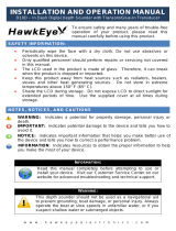
B. Aligning Ratchets on Transducer bracket
You will use the ratchets to ensure the transducer is installed parallel to
the ground.
Insert the ratchets in the bracket with the letter “A” 1.
aligned with the dot stamped on the outside of the
transducer bracket.
Slide the transducer into the bracket and temporarily 2.
slide the bolt through the transducer bracket.
Good locations
Poor locations
Align dot and letter
"A".
dot
A
Ratchet
Bracket
Installation

4
Hold the transducer assembly against the transom. Look at 3.
the transducer from the side. If it is parallel to the ground,
then the “A” position is correct.
If the transducer can not be adjusted so its face is parallel 4.
to the ground, remove the transducer and ratchets from
the bracket. Reinsert the ratchets into the bracket, this
time with the letter “B” aligned with the dot stamped in the
bracket. Reassemble the transducer and bracket and place
it against the transom.
Check to see if the transducer will adjust so its face is parallel with the ground. 5.
Repeat this process until the transducer can be adjusted so its face is parallel
with the ground.
C. Assembling the bracket
After determining the correct position for
the ratchets, loosely assemble the transducer
and bracket assembly.
Lock nut
Metal washer
Rubber washers
Ratchets
Metal washer
Bolt
Installation
Place the
transducer and
bracket against
the transom.

5
D. Attaching Transducer to Transom
Adjust the transducer so its face is parallel with the 1.
ground and its center line is even with the bottom
of the boat hull.
Hold the transducer and bracket assembly against 2.
the transom. When the transducer and bracket
are properly aligned mark its position on the hull.
Drill the mounting holes for the transducer bracket. 3.
Use a #29 bit (for the #10 screws).
Routing cables
When mounting your transducer, make sure to leave some slack in the cable near the transducer.
If you need to drill a hole in the transom to pass the connector
through, the hole size will depend on the connector on the end of the
transducer’s cable.
Installation
The transducer centerline must
be even with the boat hull. Its face
should be parallel to the ground.
Transom
Bottom
of hull
Waterline
Do not overtighten the lock nut; otherwise the transducer
will not be able to kick up if it strikes an object
Run cable over the bolt
and through the bracket.

6
E. Make a test run
After the transducer is installed make a test run to ensure the transducer is installed properly.
Use the slots in the transducer mounting bracket to loosen the screws and slide the transducer
up or down, if adjustments are necessary.
Shoot-thru-hull Skimmer & Pod transducer installation
Before attempting any installation on boats with otation material sandwiched within the hull,
consult the boat manufacturer.
In a shoot-thru-hull installation the
transducer is epoxied to the inside of the
boat hull.
A transducer can not shoot through wood
or metal hulls. Wood and metal hulls
require either a transom mount or thru-
hull installation.
WARNING: Do not remove material from the inner hull. Careless grinding on
the hull could damage hull integrity. Contact the boat dealer or manufacturer to
conrm hull specications
.
Transducer epoxied to hull
Epoxy
Transducer
Hull
Keel pad
Installation

7
For shoot-thru-hull applications many boat hulls have a at keel pad that offers a good transducer
mounting surface.
Make sure the Skimmer transducer is oriented so the nose of the transducer is facing the bow
(front) of the boat. If the transducer has a
built in temp sensor, it will only show the
temperature of the hull, not the water temp.
Before you epoxy the transducer to the hull,
make sure the area is clean, dry and free of
oil or grease.
The surface of the hull must be at so the entire transducer face is in contact with the hull. Also,
make sure the cable is long enough to reach the sonar unit.
To use shoot-thru-hull installation:
Sand the inside surface of the hull, where the transducer is to be epoxied, and 1.
the face of the transducer. Sand the hull until it is smooth to the touch. The
sanded area should be about 1-1/2 times the diameter of the transducer.
2. After sanding, clean the hull and the face of the transducer with an alcohol
wipe to remove any dust.
On vee hulls
try to place the
transducer where
the dead rise is
10° or less.
Installation

8
Apply a thin layer of epoxy (about 1/16” or 1.5 3.
mm) on the face of the transducer and the
sanded area on the hull. Be careful when
mounting a transducer inside a boat hull.
Once epoxied into position, the transducer
can not be removed.
Press the transducer into the epoxy, turning 4.
it to force out any air bubbles from under the
transducer face. Make sure there are no air
pockets in the epoxy layers.
Stop pressing when it bottoms out on the hull. 5.
Apply pressure to hold the transducer in place
while the epoxy sets. Be careful not to move
the transducer while the epoxy is setting. Allow
the epoxy to set before moving the boat.
When nished, the face of the transducer should 6.
be parallel with the hull with a minimum amount
of epoxy between the hull and transducer.
Sand transducer face
and mounting location
Apply epoxy to transducer
face and mounting location.
Epoxy transducer to hull.
HullEpoxy
Installation

9
Trolling motor Skimmer and Pod Installation
The TMB-S trolling motor bracket (Part No. 51-45) is an optional accessory and is available
through LEI Extras at www.lei-extras.com. The TMB-S bracket is used to attach a one-piece
bracket skimmer transducer to a trolling
motor.
The Pod transducer does not need a TMB-S
trolling motor bracket to be installed on a
trolling motor. It only needs a hose clamp
(adjustable strap).
Installing transducer on trolling motor:
Using the components supplied with the TMB-S bracket attach the skimmer 1.
transducer to the bracket as shown
in the diagram.
Slide the adjustable strap (hose 2.
clamp) through the plastic bracket
on the skimmer transducer or
through the Pod transducer slots
and then slip the strap around the
trolling motor.
Flat washer
Lock
nut
Bolt
Internal tooth
washer
Plastic bracket
Adjustable strap
Plastic ties (not
included)
Move transducer
cable to back
side of shaft
Installation

10
Position the transducer so its face is pointing straight down when the trolling 3.
motor is in the water.
Tighten the adjustable strap 4.
securely to the trolling motor.
Make sure there is enough slack
in the transducer cable for the
trolling motor to turn freely.
Mounting display unit
Before mounting the display unit mount, make sure there is nothing in the area that will obstruct
the display unit when it is installed on the bracket.
To install bracket mount:
Place the bracket on the desired mounting surface and mark the four mount-1.
ing holes. If you want to run the unit’s cables up through the mounting surface,
make a mark in the center of the bracket mounting surface.
Drill pilot holes for the four mounting holes. If desired, use a 1-inch (25mm) bit 2.
to drill the center cabling hole in the mounting surface.
The top of the Pod
transducer is curved to t
the contour of the trolling
motor, so you do not
need a TMB-S mounting
bracket.
Installation

11
If you are running the cables up through the mounting surface, push the cables 3.
through the mounting surface and then pull them through the cabling hole in
the center of the bracket.
Align the mounting bracket with the four mounting holes and use the supplied 4.
screws to fasten it to the mounting surface.
Connect the display unit to the bracket mount. 5.
Connecting display unit to bracket.
Installation

12
Connecting to Power
Connect the black wire to a 1.
ground.
Attach a 3 Amp fuse to the end 2.
of the power wire and then con-
nect the fuse to the positive (+)
terminal on the battery. (Use 18
gauge wire to extend the power
or ground wires.)
Connect the Power cable to the 3.
Power port on the back of the dis-
play unit.
12V
Optional paddlewheel
speed/temp sensor
Optional
temp
sensor
Black (ground)
wire
3 Amp
fuse
Red (power)
wire
Speed/
Temp
port
Power
port
Installation

13
ZOOM Keys: used to
zoom in/zoom out
PAGES: Opens
pages menu; allows
you to select a page
to view
KEYPAD: controls
cursor & selects
items on menus
MENU: Opens
settings, context
and page menus
ENTER: nalizes
menu selections
LIGHT/POWER: controls
backlight level and turns
unit on/off
Basic Operation
Fish arches
Surface Clutter
Overlay
Data
Frequency
Range
Scale
Amplitude
Scope
Colorline

14
Basic Operation
Getting Started
Turn unit
on/off
To turn on/off the unit, press
and hold the LIGHT/POWER
key for three seconds.
Adjusting
the
backlight
Press the
LIGHT/POWER
key, select Brightness and
press the keypad left/right.
Muting
Audio
Select Mute Audio from
the System menu and press
ENTER.
Pages
This unit has four page screens: Sonar, Split
Zoom, Split Frequency and Split Flasher.
Sonar
Displays the water column
moving from right to left
on your unit’s screen.
Split Zoom
Displays a 2X zoom in the
left panel with the sonar view
in the right panel.
Split Frequency
Displays 83 kHz frequency
in the left panel and 200kHz
view in the right panel.
(Mark 5x Pro and Elite 5x)
Split Flasher
Displays a sonar asher in
the left panel with the sonar
view in the right panel.

15
Accessing Settings menu
Selecting Menu items
Accessing Pages
Accessing Sonar menu
Sonar menu
Settings menu
Basic Operation
Settings
menu
Sonar settings
menu

16
Entering text
To input text:
Select the desired character and 1.
press ENTER.
Repeat Step 1 for each 2.
character.
When text entry is completed, 3.
highlight OK and press ENTER.
Basic Operation
Switches
keyboard between
Alpha and Qwerty
layout
Switches letters
to uppercase/
lowercase
Working with menus
Scrollbars
Select the scrollbar and press
the keypad left (decrease) or
right (increase).
On/Off features
Select an on/off menu item
and press ENTER.
Dropdown menus
Press the keypad up/down
to select the desired item
and press ENTER.

17
Fishing Mode Options
General Use
Bottom brown/blue background;
50% ping speed
Shallow Water
Bottom brown/white background;
best suited for depths less than
100 feet
Fresh Water
Bottom brown/white background;
50% ping speed
Deep Water Deep Blue; 50% ping speed
Slow Trolling
Bottom brown/white background;
50% ping speed
Fast Trolling
Bottom brown/white background;
slightly lower chart speed
Clear Water
Bottom brown/white background;
50% ping speed
Brackish
Water
Bottom brown/blue background;
higher ASP; slightly lower chart
speed
Basic Operation
Exiting menus
If a screen or menu has an exit option (Close,
Return to screen, Exit dialog) highlight the
exit option and press ENTER to exit.
If there is no exit option press the
MENU key repeatedly to close all
menus.
Selecting a Fishing Mode
Fishing modes are preset
packages of sonar settings
geared to specic shing
conditions.
NOTE: Use Shallow Water mode
when shing in less than 100 feet
of water; otherwise your unit
may not track bottom properly.

18
Basic Operation
Advanced Mode
Enables advanced
features and settings.
Advanced Mode features
Custom
range
Enables Upper and Lower Limits
Sensitivity Enables manual control of sensitivity
Colorline Enables manual control of colorline
Surface
Clarity
Enables manual control of surface
clarity
Ping Rate Enables manual control of ping rate
Alarms
Enables Arrival, Off Course and
Anchor alarms
Units
Enables units for Distance, Speed,
Depth, Temperature and Bearings
Restoring Defaults
Resets unit options and set-
tings to defaults.
Standby mode
Lowers power consumption by putting the
unit into a sleep mode and turning off sonar.
Press any key to resume normal operation.
Elite 5x
backlight menu
Mark series
backlight menu
WARNING: Leaving the unit in
Standby with the boat turned
off will drain the battery.
/