Page is loading ...

INSTALLATION &
OPERATION MANUAL
8128 River Way, Delta B.C. V4G 1K5 Canada T. 604.946.9981 F. 604.946.9983 TF. 800.668.3884 (US/CANADA)
www.AnalyticSystems.com
An ISO9001 Registered Company Battery Chargers • Inverters • Power Supplies • Voltage Converters
VTC120 SERIES
VOLTAGE CONVERTER

2
SAVE THESE INSTRUCTIONS — This manual contains important safety and operating
instructions for the voltage converter.
VOLTAGE CONVERTER PRECAUTIONS
1. Do not expose the voltage converter to rain or snow unless it is a sealed model.
2. Use of an attachment not recommended or sold by the manufacturer may result in a
risk of re, electric shock, or injury to persons.
3. Do not disassemble the voltage converter. If service or repair is required, return it to
the manufacturer or an authorized service center. Incorrect reassembly may result in
a risk of re or electric shock. Voltages up to 350 volts are present inside the voltage
converter any time it is connected to input power source, even if it is switched OFF.
4. To reduce risk of electric shock, disconnect the voltage converter from the input power
before attempting any maintenance or cleaning. Switching the voltage converter to
OFF will not reduce this risk.
5. Never place the voltage converter directly above a battery; gases from the battery will
corrode and damage the voltage converter.
6. Never allow battery acid to drip onto the voltage converter.
VOLTAGE CONVERTER
IMPORTANT SAFETY INSTRUCTIONS
MEDICAL EQUIPMENT NOTICE
Analytic Systems does not recommend the use of their products in life support
applications where failure or malfunction of this product can be reasonable
expected to cause the failure of the life support device or to signicantly affect
its safety or effectiveness. Analytic Systems does not recommend the use of its
products in direct patient care.
Examples of devices considered to be life support devices are: neonatal oxygen
analyzers, nerve stimulators (whether used for anesthesia, pain relief, or other
purposes), auto-transfusion devices, blood pumps, debrillators, arrhythmia
detectors and alarms, pacemakers , hemodialysis systems, peritoneal systems,
neonatal ventilator incubators, ventilators for both adults and infants, anesthesia
ventilators, and infusion pumps as well as any other devices designated as
“critical” by the U.S. FDA.

3
TABLE OF CONTENTS
• Front Cover
• Product Warnings and Advisories
• Table of Contents
• Introduction
• Main Parts
• Box Contents
• Installation
• Operation
• Troubleshooting
• Specications
• Warranty
Revised - April 18, 2019
Copyright (2005-2019) Analytic Systems Ware (1993) Ltd.

4
Introduction
The VTC120 Series Voltage Converter is a variable duty cycle switching voltage converter with
a precision linear regulator output. It can be congured to run from a 12 VDC or 24 VDC input
battery voltage to provide output voltages of 12 VDC, 24 VDC, or 48 VDC. All VTC120 series
models are fully isolated from the input (up to 500 VDC).
Applications of this unit include:
• Running 24V PLC controls from a 12 Volt battery system.
• Any application requiring 24 VDC when only 12 VDC is available.
• Providing ground isolation between two 12 VDC or 24 VDC power systems, or between a
12 VDC and 24 VDC power system.
In addition to the VTC120 series, Analytic Systems also manufactures the VTC120h series, a
high power output version of the standard model. These models supply a higher output current
than the standard models (7.5 A Continuous/ 8 Amp Peak) and are built with appropriate fuses
for the higher current.
Box Contents
The box that you’ve received should contain:
• One VTC120 DC/DC Voltage Converter
• This User Guide (a .PDF copy can be downloaded from www.AnalyticSystems.com)
• One Warranty Registration Card
If anything is damaged or missing from your box, please contact us by e-mailing [email protected]

5
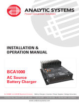
Main Parts
1. DC Output Connection: 4-pin
Phoenix Connector (Pins 1 and 2)
2. Output Power LED
3. DC Input Connection: 4-pin
Phoenix Connector (Pins 3 and 4)
4. Input Power LED
5. Power Switch
2
3
5
Front Panel
1
4

6
Installation
MOUNTING
Mount the unit in a DRY and WELL VENTILATED location. Allow at least 1 inch of clearance
around the unit for adequate cooling.
POWER CONNECTION
This unit is equipped with a 4-pin Phoenix connector to serve as both an input and output
connection. The polarity of this connection can be found on top panel label.
Max. Output Current 24.00 A 15.00 A 9.30 A 5.90 A 3.70 A
American Wire Gauge #8AWG #10AWG #12AWG #14AWG #16AWG
Max. Output Current 2.30 A 1.50 A 0.92 A 0.58 A 0.23 A
American Wire Gauge #18AWG #20AWG #22AWG #24AWG #28AWG
IMPORTANT: The wire gauge used for the input/output connections is of a suitable gauge
for the input current rating and output current rating, respectively. See Specications for more
details.
Pin Polarity
1 Input Positive
2 Input Negative
3 Output Negative
4 Output Positive
IMPORTANT: Ensure that the total average load of all devices connected to the output does
not exceed the continuous current rating of the unit. If multiple devices are connected to the
output of the voltage converter, they must share a common ground! See Specications for
more details.

7
Operation
This VTC120 is designed for simple and intuitive operation. Before using the voltage converter,
it must be properly installed and connected to the load and power source. For more information,
see Installation.
TO START OPERATION
1. Move the Power Switch to the ON position.
2. The INPUT LED and OUTPUT LED will both glow green indicating that the circuitry is
energized.
3. The voltage converter will automatically begin supplying the voltage listed on the label to
any connected devices.
TO END OPERATION
1. Move the Power Switch to the OFF position.
2. Wait for the INPUT LED and OUTPUT LED to stop glowing.
3. Once the LEDs is dim, it is safe to disconnect the power source and load from the voltage
converter. The unit is ready for storage or service.

8
Troubleshooting
The table below details malfunctions that voltage converter may experience during installation or
operation, the cause of those malfunctions, and the suggested course of action correcting them.
Issue: The unit is not supplying the listed output voltage
Cause:
If the current being drawn by the connected devices exceeds the unit’s peak
output current rating for too long of a time, the unit will drop the output
voltage to try and maintain the current at its maximum level.
Fix:
Check the output current with a multimeter. If the unit is overloaded, reduce
the load by disconnecting some devices from the voltage converter.
Issue: The input fuse blows with the unit is turned ON
Cause:
The power source is likely connected in the reverse polarity.
Fix:
Check the polarity of the input connection and correct it if reversed. If
this connection is correct, the cause of the blown fuse is an internal
component failure and the unit must be returned for service.
Issue: The input LED does not turn glow when the power source is connected
Cause:
The unit is not detecting the minimum input voltage required for normal
operation.
Fix:
Check that the input power source is supplying the rated voltage
using a multimeter. Check that the input connection is not damaged or
discontinuous. If there are no problems with the power source or input
connection, the cause of the failure is an internal component failure and
the unit must be returned for service.

9
Specications
12 Volt Input Models
Model VTC120-12-12 VTC120-12-24 VTC120-12-48
Input Voltage 11 – 15 VDC
Maximum Input Amps 8.5 A 15 A 30 A
Input Fuse AGC-10 AGC-20 AGC-30
Output Voltage 12.0 VDC 24.0 VDC 48.0 VDC
Output Amps 5 Continuous / 5.5 Peak
Mechanical
Length 5.3 in / 13.5 cm
Width 7.9 in/ 20.1 cm
Height 2.4 in / 6.1 cm
Clearance 1.0 in / 2.5 cm all around
Weight 3.0 lb / 1.36 kg
Material and Finish Marine Grade Black Anodized Aluminum
Fasteners 18-8 Stainless Steel
Connections Input/ Output - 4-pin Phoenix Connector
Isolation > 500 VDC (Input-Output)
48 Volt Input Models
Model VTC120-48-12 VTC120-48-24 VTC120-48-48
Input Voltage 40 – 60 VDC
Maximum Input Amps 2.1 A 4.2 A 8.4 A
Input Fuse MDA-5 MDA-5 AGC-10
Output Voltage 12.0 VDC 24.0 VDC 48.0 VDC
Output Amps 5 Continuous / 5.5 Peak 5 Continuous / 5.5 Peak 2.5 Cont. / 5.5Peak
24 Volt Input Models
Model VTC120-24-12 VTC120-24-24 VTC120-24-48
Input Voltage 22 – 30 VDC
Maximum Input Amps 3.8 A 7.5 A 15 A
Input Fuse MDA-6 AGC-10 AGC-20
Output Voltage 12.0 VDC 24.0 VDC 48.0 VDC
Output Amps 5 Continuous / 5.5 Peak

10
High Output
Model (VTC120X) h-12-12 h-12-24 h-24-12 ih-24-24 ih-48-12 ih-48-24
Input Volts (DC) 11 – 15 11 – 15 22 – 30 22 – 30 40 – 60 40 – 60
Input Amps (max) 11 21.8 6.2 10.9 3.0
Input Fuse AGC-15 AGC-25 MDA-7 AGC-15 MDA-7 AGC-15
Output Volts (DC) 12.0 24.0 12.0 24.0 12.0 24.0
Output Amps 7.5 Continuous / 8.0 Peak
Isolation Input-Output > 500 VDC
Environmental and Safety
Operating Temperature Range
-25°C to +40°C @ maximum output. Derate Linearly 2.5% per °C from 40°C
(Optional -40°C extra wide temperature operation available)
Humidity 0 - 95% Relative Humidity (non-condensing) with standard conformal coating
Audible Noise 0 dB
Typical Service Life > 10 years (87,600 hrs)
Warranty Three years parts and labor
Safety Built to meet CSA 22.2.107.1 & UL458
*Specications subject to change without notice.
Designed and manufactured by: ANALYTIC SYSTEMS WARE (1993) LTD.
8128 River Way
Delta, BC V4G 1K5 Canada
p. 604.946.9981 f. 604.946.9983
tf. 800.668.3884 US/Canada
www.analyticsystems.com [email protected]

11
Limited Warranty
1. The equipment manufactured by Analytic Systems Ware (1993) Ltd. (the “Warrantor”) is warranted to be free
from defects in workmanship and materials under normal use and service.
2. This warranty is in effect for:
a. 3 Years from date of purchase by the end user for standard products offered in our catalog.
b. 2 Years from date of manufacture for non-standard or OEM products
c. 1 Year from date of manufacture for encapsulated products.
3. Analytic Systems will determine eligibility for warranty from the date of purchase shown on the warranty card
when returned within 30 days, or
a. The date of shipment by Analytic Systems, or
b. The date of manufacture coded in the serial number, or
c. From a copy of the original purchase receipt showing the date of purchase by the user.
4. In case any part of the equipment proves to be defective, the Purchaser should do the following:
a. Prepare a written statement of the nature of the defect to the best of the Purchasers knowledge, and
include the date of purchase, the place of purchase, and the Purchasers name, address and telephone
number.
b. Call Analytic Systems at 800-668-3884 or 604-946-9981 and request a return material authorization
number (RMA).
c. Return the defective part or unit along with the statement at the Purchasers expense to the Warrantor;
Analytic Systems Ware (1993) Ltd., 8128 River Way, Delta, B.C., V4G 1K5, Canada.
5. If upon the Warrantor’s examination the defect proves to be the result of defective material or workmanship,
the equipment will be repaired or replaced at the Warrantor’s option without charge, and returned to the
Purchaser at the Warrantor’s expense by the most economical means. Requests for a different method of return
or special handling will incur additional charges and are the responsibility of the Purchaser.
6. Analytic Systems reserves the right to void the warranty if:
a. Labels, identication marks or serial numbers are removed or altered in any way.
b. Our invoice is unpaid.
c. The defect is the result of misuse, neglect, improper installation, environmental conditions, non-
authorized repair, alteration or accident.
7. No refund of the purchase price will be granted to the Purchaser, unless the Warrantor is unable to remedy the
defect after having a reasonable number of opportunities to do so.
8. Only the Warrantor shall perform warranty service. Any attempt to remedy the defect by anyone else shall
render this warranty void.
9. There shall be no warranty for defects or damages caused by faulty installation or hook-up, abuse or misuse of
the equipment including exposure to excessive heat, salt or fresh water spray, or water immersion except for
equipment specically stated to be waterproof.
10. No other express warranty is hereby given and there are no warranties that extend beyond those described
herein. This warranty is expressly in lieu of any other expressed or implied warranties, including any implied
warranty of merchantability, tness for the ordinary purposes for which such goods are used, or tness for a
particular purpose, or any other obligations on the part of the Warrantor or its employees and representatives.
11. There shall be no responsibility or liability whatsoever on the part of the Warrantor or its employees and
representatives for injury to any person or persons, or damage to property, or loss of income or prot, or any
other consequential or resulting damage which may be claimed to have been incurred through the use or sale of
the equipment, including any possible failure of malfunction of the equipment, or part thereof.
12. The Warrantor assumes no liability for incidental or consequential damages of any kind

Register Products Online | www.analyticsystems.com/support/warranty-registration
DESIGNED AND MANUFACTURED BY
800-668-3884
604-946-9983
www.AnalyticSystems.com
8128 River Way
Delta, BC V4G 1K5 | Canada
Battery Chargers • Inverters • Power Supplies • Voltage Converters
/