Page is loading ...

L8543010
12/2012 Rev. 0
LADY 5
BARRIERE STRADALI
ROAD BARRIERS
STRASSENSCHRANKEN
BARRIÈRES LEVANTES
BARRERAS DE CARRETERAS
SZLABANY DROGOWE
Libro istruzioni e catalogo ricambi
Operating instructions and spare parts catalogue
Betriebsanleitung und Ersatzteilliste
Livret d’instructions et catalogue des pieces de rechange
Manual de instrucciones y catálogo de recambios
Książeczka z instrukcjami i katalog części wymiennych
UNIONE NAZIONALE COSTRUTTORI
AUTOMATISMI PER CANCELLI, PORTE
SERRANDE ED AFFINI

2
Dati tecnici
Technical data
Technische Daten Données technique
Datos técnicos
Dane techniczne
LADY 5
Alimentazione
Alimentazione motore
Assorbimento motore
Coppia
Grado di protezione
Intermittenza lavoro
Temp. funzionamento
Tempo apertura
Lubrificazione
Rumorosità
Peso
Feed
Motor feed
Motor consumption
Torque
Degree of protection
Jogging
Operating temp.
Opening time
Lubrication
Noise level
Weight
Versorgung
Motorspeisung
Motorstromaufnahme
Drehmoment
Schutzart
Betriebsintervall
Betriebstemperatur
Öffnungszeit
Schmierung
Geräuschentwicklung
Gewicht
Alimentation
Alimentation moteur
Absorption moteur
Couple
Indice de protection
Intermittence travail
Temp. fonctionnement
Temps d’ouverture
Lubrification
Bruit
Poids
Alimentación
Alimentación del motor
Absorción motor
Par
Grado de protección
Intermitencia de trabajo
Temp. de funcionamiento
Tiempo de apertura
Lubricación
Ruido
Peso
Zasilanie
Zasilanie silnika
Pobór mocy silnika
Moment obrotowy
Stopień ochrony
Cykliczność pracy
Temp. podczas pracy
Czas otwierania
Smarowanie
Max. halas
Ciężar
230 Vac
24 Vdc
1,6 A
205 Nm
IP44
*
-20°C/+50°C
**
***
<70dB (A)
52 kg
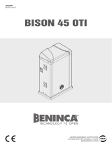
222
40
324
1008
MAX. 5,0m
MIN. 2,0m
MAX. 5,2m
MIN. 2,2m
Dimensioni d’ingombro
Overall dimensions
Platzbedarf
Dimensions d’encombrement
Dimensiones totales
Wymiary gabarytowe
* Uso intensivo - Intensive use - Intensive Nutzung - Usage intensif - Uso intensivo - Użytkowanie intensywne
** Vedi tabella A - See table A - Siehe Tabelle A - Voir tableau A - Ver cuadro A - Zobacz tabelę A
*** Grasso permanente - Permanent grease - Permanentfett - Graisse permanente - Grasa permanente - Smar trwały
TAB A
Alimentazione motore
Motor feed
Motorspeisung
Alimentation moteur
Alimentación del motor
Zasilanie silnika
Tempo di apertura
Opening time
Öffnungszeit
Temps d’ouverture
Tiempo de apertura
Czas otwierania
(s)
Tempo di chiusura
Closing time
Schließenzeit
Temps de fermeture
Tiempo de cierre
Czas zamknięcia
(s)
Lunghezza asta
Bar length
Stangenlänge
Longueur lisse
Largura del asta
Długość ramienia
(MAX)
26 Vdc 3 4 4m
23 Vdc 4 5 5m
18 Vdc 5 6 5m
I tempi indicati comprendono i rallentamenti
The indicated time is inclusive of braking time.
Die angegebenen Zeiten berücksichtigen Verzögerungen.
Les temps indiqués comprennent les ralentissements.
Los tiempos indicados incluyen las ralentizaciones.
Czas podany łącznie z czasem opóźnienienia.

3
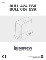
TAB.1
LADY 5
Lunghezza asta (m) - Bar length (m) - Stangenlänge (m))
Longueur lisse (m) - Largura del asta (m) - Długość ramienia (m)
Accessori utilizzabili - Accessories for use
Verwendbares Zubehör - Accessoires utilisables
Accesorios utilizables - Stosowane akcesoria
2,2 2,7 3,2 3,7 4,2 4,7 5,2
NA
C C C B A B C
LADY.P(1)
C C B B A A A
LADY.P(2)
C C B B A A A
VE.RAST
C B B A A
LADY.P(1) + VE.RAST
C B B A
LADY.P(1) + VE.AM
C B B A A A A
LADY.P(2) + VE.AM
C B B A A
LADY.P(1) + VE.RAST + VE.AM
C B A
SC.RES
C B B A A
LADY.P (1) + SC.RES
C B A A
SC.RES + VE.AM
C B A A
LADY.P(1)+ SC.RES + VE.AM
C B A
VE.RAST + VE.AM
C B B A A
C
B
A
Fig.1
Legenda
NA Nessun accessorio
LADY.P(1) Profilo di protezione (solo superiore).
LADY.P(2) Profili di protezione (superiore e inferiore).
VE.RAST Rastrelliera in alluminio.
VE.AM Appoggio mobile per asta.
SC.RES Bordo sensibile resistivo (conforme all’alle-
gato 4 della Direttiva Macchine).
Attenzione:
L'installazione della VE.RAST pregiudica l'uso della SC.RES
e viceversa.
L'installazione del kit luci LADY.L non influenza il bilancia-
mento dell'asta
Key
NA
No accessories
LADY.P(1)
Protection profile (only upper).
LADY.P(2)
Protection profiles (upper and lower).
VE.RAST
Aluminium skirt.
VE.AM
Mobile support for bar.
SC.RES
Sensitive resistive edge (complying with
annexe 4 of the Machines Directive).
Attention:
The installation of the
VE.RAST
interferes with the use of the
SC.RES
and vice versa.
The installation of the
LADY.L
lights kit does not influence
the balancing of the bar
Legende
NA
Kein Zubehör
LADY.P(1)
Schutzprofil (nur oben).
LADY.P(2)
Schutzprofile (oben und unten).
VE.RAST
Unterfahrsperre aus Aluminium
VE.AM
Bewegliche Stangenauflage.
SC.RES
Resistive Kontaktleiste (gemäß Anlage 4 der
Maschinenrichtlinie).
Achtung:
Die Installation der
VE.RAST
beeinträchtigt den Einsatz der
SC.RES
und umgekehrt.
Die Installation des Beleuchtungskits
LADY.L
beeinflusst nicht
die Auswuchtung der Stange
Légende
NA
Aucun accessoire
LADY.P(1)
Profil de protection (supérieur).
LADY.P(2)
Profils de protection (supérieur et inférieur)
.
VE.RAST
Filet de lisse en aluminium.
VE.AM
Appui mobile pour lisse.
SC.RES
Barre palpeuse (bord sensible de sécurité à
variation de résistance conforme à l’annexe
4 de la Directive Machines).
Attention:
L’installation de la
VE.RAST
empêche l’emploi de la
SC.RES
et vice-versa. L’installation du kit lumières
LADY.L
n’influence
pas l’équilibrage de la lisse
Leyenda
NA
Ningún accesorio
LADY.P(1)
Perfil de protección (sólo superior).
LADY.P(2)
Perfiles de protección (superior e inferior).
VE.RAST
Faldilla en aluminio.
VE.AM
Apoyo móvil para asta.
SC.RES
Bordo sensible resistivo (conforme al anexo
4 de la Directiva Máquinas).
Atención:
Si se instala el VE.RAST no se podrá utilizar el SC.RES, y
viceversa.
La instalación del kit luces LADY.L no afecta al equilibrado
del asta
Opis
NA Bez akcesoriów
LADY.P(1) Odbojnica ochronna (tylko górna).
LADY.P(2) Odbojnice ochronne (górna i dolna).
VE.RAST Drabinka aluminiowa.
VE.AM Słupek podpierający ramię, ruchomy.
SC.RES Obrzeże czujnikowe rezystywne (zgodne
z wytycznymi załącznika 4 do Dyrektywy
dla Maszyn).
Uwaga:
Instalacja drabinki VE.RAST uniemożliwia stosowanie
obrzeża SC.RES i odwrotnie. Instalacja zestawu świateł
LADY.L nie wpływa na wyważenie ramienia szlabanu

5
Piastra.
Plate.
Platte.
Platine
Placa.
Płyta
Asta LADY.A.
Bar LADY.A.
Stange LADY.A.
Lisse LADY.A.
Asta LADY.A.
Ramię LADY.A
Supporto.
Support.
Auflage.
Support.
Soporte.
Wspornik
Colonna
Column
Säule
Fût
Columna
Kolumna
Vite M14x30 UNI 5933.
Screw M14x30 UNI 5933.
Schraube M14x30 UNI 5933.
Vis M14x30 UNI 5933.
Tornillo M14x30 UNI 5933.
Sruba M14x30 UNI 5933
Vite M8x16 UNI 5931.
Screw M8x16 UNI 5931.
Schraube M8x16 UNI 5931.
Vis M8x16 UNI 5931.
Tornillo M8x16 UNI 5931.
Sruba M8x16 UNI 5931
Rosetta Ø8.4x17 UNI 6592.
Washer Ø8.4x17 UNI 6592.
Unterlegscheibe Ø8.4x17 UNI 6592.
Rondelle Ø8.4x17 UNI 6592.
Arandela Ø8.4x17 UNI 6592.
Podkładka Ø 8.4x17 UNI 6592
V ring (V 60A).
V ring (V 60A).
V ring (V 60A).
V ring (V 60A).
V ring (V 60A).
V ring (V 60A)
Fig.3

9
Fig.8
Finecorsa di apertura (B)
Opening limit stop (B)
Endschalter Öffnen (B)
Fin de course d’ouverture (B)
Fin de carrera de apertura (B)
Krańcówka otwarcia (B)
C
Camma finecorsa rallentamento chiusura
Slowing and closing limit stop cam
Endschalternocken Verlangsamung und Ver-
schluss
Came fin de course ralentissement et fer-
meture
Leva fin de carrera de deceleración y cierre
Krzywka krańcówki na zwalnianie i zamnk-
nięcia
A
Camma finecorsa apertura
Opening limit stop cam
Endschalternocken Öffnen
Came fin de course d’ouverture
Leva fin de carrera de apertura
Krzywka krańcówki otwarcia
+
Anticipa l’azione frenante.
Anticipate the braking action.
Vorverlegung der Abbremswirkung.
Anticipe l’action freinante.
Anticipa la acción frenante.
Przyspiesza hamowanie.
-
Posticipa l’azione frenante.
Delay the braking action.
Nachverlegung der Abbremswirkung.
Retarde l’action freinante.
Retarda la acción frenante.
Opóźnia hamowanie.
Fig.9
Finecorsa di rallentamento (C)
Slowing limit stop (C)
Verlangsamungs-Endschalter (C)
Fin de course de ralentissement (C)
Fin de carrera de deceleración (C)
Krańcówka na zwalnianie (C)
Finecorsa di chiusura (D)
Closing limit stop (D)
Endschalter Schließen (D)
Fin de course de fermeture (D)
Fin de carrera de cierre (D)
Krańcówka zamknięcia (D)
Fermo meccanico ammortizzato in
apertura
Damped mechanical stop on ope-
ning
Gedämpfte mechanische Feststellvor-
richtung beim Öffnen
Butée mécanique amortie en
ouverture
Tope mecánico amortiguado en
apertura
Blokada mechaniczna amortyzowa-
na w otwarciu
Fermo meccanico chiusura
Mechanical stop on closing
Mechanische Feststellvorrichtung Schließen
Butée mécanique fermeture
Tope mecánico de cierre
Blokada mechaniczna zamknięcia
Grani di bloccaggio
Blocking dowels
Arretierstifte
Goujons de blocage
Tornillos sin cabeza de bloqueo
Kołki blokujące
V

10
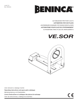
1 Centrale di comando DA.24V
2 Fotocellula trasmettitore FTC
3 Fotocellula ricevente FTC
4 Lampeggianti LADY.L
5 Bat. a tamp. N° 2-12V-6 Ah collegate in serie
6 Colonnina fotocellula per barriera LADY.COL
7 Gomma di protezione inferiore/superiore LADY.P
8 Costa pneumatica SC.RES
9 Circuito SC.E di interfaccia tra SC.RES e DA.24V
1 Control unit DA.24V
2 Transmitting photocell FTC
3 Receiving photocell FTC
4 Blinking lights LADY.L
5 N° 2-12V-6 Ah buffer batteries connected in series
6 Photocell column for barrier LADY.COL
7 Bottom/top rubber protection LADY.P
8 Pneumatic edge SC.RES
9 SC.E interface circuit between SC.RES and
DA.24V
2
3
3x1
2x1
2x1
9
4
7
8
1
5
+
+
-
-
2x1
4x1
2x2
2x1.5
230 V
6
1 Steuerzentrale DA.24V
2 Photozelle Sender FTC
3 Photozelle Empfänger FTC
4 Blinkleuchten LADY.L
5 Pufferbatterie. N° 2-12V-6 Ah in Serie geschaltet
6 Photozellensäule für Schranke LADY.COL
7 unterer/oberer Schutzgummi LADY.P
8 pneumatische Kontaktleiste SC.RES
9 SC.E-Kreis als Schnittstelle zwischen SC.RES und
DA.24V
1 Logique de commande DA.24V
2 Photocellule émetteur FTC
3 Photocellule récepteur FTC
4 Clignotants LADY.L
5 2 Batteries tampon 12V-6 Ah connectées en série
6 Colonne photocellule pour barrière LADY.COL
7 Profil de protection inférieur/supérieur en caoutchouc
LADY.P
8 Barre palpeuse SC.RES
9 Circuit SC.E d’interface entre SC.RES et DA.24V
1 Central de comando DA.24V
2 Fotocélula del transmisor FTC
3 Fotocélula del receptor FTC
4 Lámparas destellantes LADY.L
5 Bat. tamp. N° 2-12V-6 Ah conectadas en serie
6 Columna fotocélula para barrera LADY.COL
7 Goma de protección inferior/superior LADY.P
8 Banda neumática SC.RES
9 Circuito SC. y de interfaz entre SC.RES y DA.24V
1 Centralka sterowania DA.24V
2 Fotokomórka przekaźnikowa FTC
3 Fotokomórka odbiornikowa FTC
4 Światła migające LADY.L
5 Akum. podtrzym. N° 2-12V-6 Ah połączone szerego-
wo
6 Kolumienka fotokomórki dla ramienia LADY.COL
7 Ochrona gumowa dolna/górna LADY.P
8 Skuwka pneumatyczna SC.RES
9 Obwód SC.E interfejsu pomiędzy SC.RES i DA.24V
Schema impianto elettrico LADY 5
Wiring diagram LADY 5
Schaltplan der Elektroanlage LADY 5
Schéma installation électrique LADY 5
Esquema instalación eléctrica LADY 5
Schemat instalacji elektrycznej LADY 5

14
The product shall not be used for purposes or in ways
other than those for which the product is intended for and
as described in this manual. Incorrect uses can damage
the product and cause injuries and damages.
The company shall not be deemed responsible for the
non-compliance with a good manufacture technique of
gates as well as for any deformation, which might occur
during use.
Keep this manual for further use.
Qualified personnel, in compliance with regulations in force,
shall install the system.
Packaging must be kept out of reach of children, as it can
be hazardous. For disposal, packaging must be divided
the various types of waste (e.g. carton board, polystyrene)
in compliance with regulations in force.
The installer must supply all information on the automatic,
manual and emergency operation of the automatic system
and supply the end user with instructions for use.
WARNING
;
An omnipolar switch/section switch with remote
contact opening equal to, or higher than 3mm
must be provided on the power supply mains..
Make sure that before wiring an adequate differential
switch and an overcurrent protection is provided.
Pursuant to safety regulations in force, some types of in-
stallation require that the gate connection be earthed.
During installation, maintenance and repair, cut off power
supply before accessing to live parts.
Descriptions and figures in this manual are not binding.
While leaving the essential characteristics of the product
unchanged, the manufacturer reserves the right to modify
the same under the technical, design or commercial point
of view without necessarily update this manual.
EC Declaration of Conformity
(Directive 2004/108/EC(EMC); 2006/95/EC (LVD
:Manufacturer
Automatismi Benincà SpA.
Address:
Via Capitello, 45 - 36066 Sandrigo (VI) – Italy
It is hereby stated that the product
operator for road gates
LADY 5.
is compliant with provisions set forth in the following EC Directives:
- DIRECTIVE 2004/108/EC OF THE EUROPEAN PARLIAMENT AND OF THE COUNCIL of 15 December 2004, on the harmo-
nisation of the laws of Member States relating to electromagnetic compatibility and which cancels Directive 89/336/EEC, according to the
following harmonised regulations: EN 61000-6-2:2005, EN 61000-6-3:2007.
- DIRECTIVE 2006/95/EC OF THE EUROPEAN PARLIAMENT AND OF THE COUNCIL of 12 December 2006, on the harmoni-
sation of the laws of Member States relating to electrical equipment designed for use with certain voltage limits, according to the following
harmonised regulations: EN 60335-1:2002 + A1:2004 + A11:2004 + A12:2006 + A2:2006 + A13:2008; EN 60335-2-103:2003.
- DIRECTIVE 2006/42/EC OF THE EUROPEAN PARLIAMENT AND OF THE COUNCIL of 17 May 2006, on machinery, which
amends Directive 95/16/EC, and complies with the requisites for the “partly completed machinery (almost machinery)” set forth in the
EN13241-1:2003 regulation.
• Moreover, Automatismi Benincà SpA declares that the pertaining technical documentation has been drawn up in compliance with
Attachment VII B of the 2006/42/ EC Directive and that the following requirements have been complied with: 1.1.1 - 1.1.2 - 1.1.3 - 1.1.5
- 1.2.1 - 1.2.3 - 1.2.6 - 1.3.1 - 1.3.2 - 1.3.3 - 1.3.4 - 1.3.7 - 1.3.9 - 1.5.1 - 1.5.2 - 1.5.4 - 1.5.5 - 1.5.6 - 1.5.7 - 1.5.8 - 1.5.10 - 1.5.11 - 1.5.13
- 1.6.1 - 1.6.2 - 1.6.4 - 1.7.2 - 1.7.4 - 1.7.4.1 - 1.7.4.2 - 1.7.4.3.
• The manufacturer undertakes that information on the “partly completed machinery” will be sent to domestic authorities. Transmission
ways are also included in the undertaking, and the Manufacturer’s intellectual property rights of the “almost machinery” are respected.
• It is highlighted that commissioning of the “partly completed machinery” shall not be provided until the final machinery, in which it
should be incorporated, is declared compliant, if applicable, with provisions set forth in the Directive 2006/42/EC on Machinery.
• Moreover, the product, as applicable, is compliant with the following regulations:
EN 12445:2002, EN 12453:2002, EN 12978:2003.
.Benincà Luigi, Legal Officer
..Sandrigo, 06/06/2012

15
Warnings and advice for installation
Before carrying out any work on the system, disconnect the 230Vac and the buffer batteries (if
present).
t 5IFCPYDPOUBJOJOHUIFDPOUSPMVOJUJTTFDVSFEUPCBSSJFSDBTFXJUIUXPTDSFXTUPBWPJEEBNBHFEVSJOHUSBOT-
port. Once the barrier has been positioned it possible to remove the screws and to unhook the box from the
case so as to facilitate wiring operations and the preparation of the control unit. On completing installation,
secure the box to the barrier case again.
t $POTVMUUIFDPOUSPMVOJUJOTUSVDUJPOTNBOVBMBTSFHBSETUIFSFHVMBUJPOPGUIFPQFSBUJOHUJNFTBOEMPHJDUIF
connection of the accessories and of the safety devices, etc.
1. General characteristics
Sturdily made but with a sober and pleasing design, LADY 5 road barriers are suitable for intensive use, thanks
to their 24Vdc motor. Installation and regulation are easily accomplished. Equipped with a very simple and
intuitive manual release, the barrier can be fitted with buffer batteries that allow it to operate even when there
is no power supply.
The bar made of painted aluminium is suitable for the application of all the accessories, signalling and safety
devices. In the event of contact of the bar with an obstacle, an amperometric sensor interrupts the movement
immediately.
2. Positioning the spring and the accessories for use
Depending on the length of the bar and on the type of accessories installed, before putting the spring under
tension it is necessary to choose the correct point in which to attach the spring to the lever.
The correct fastening point (“A”, “B” or “C” - Fig.1), must be chosen in table 1, depending on the length of the
bar and on the type of accessories you intend to install.
3. Laying the foundation plate (Fig.2)
After having arranged the passage of the cables (power supply, accessories, etc.), put the foundation plate in
position, referring to the measurements in fig.2.
4. Fixing the bar (Fig.3)
The bar is fixed to the plate using the support and the screws provided, as illustrated in Fig.3. We recommend
installing any accessories for the bar (protective profiles, lights, edge, skirt, etc.) before fixing it to the plate.
5. Preparing the barrier for right or left (Fig.4)
If the opening direction reversion is required, proceed as follows. If it is not necessary, go to the next section:
t &OUJSFMZVOMPBEUIFTQSJOHCZMPPTFOJOHJUBOEVOIPPLJOHJUGSPNUIFi-wBODIPSJOHMFWFS
t XJUISFGFSFODFUP'JHJOWFSUUIFQPTJUJPOPGUIFi'wBOEi'wNFDIBOJDBMTUPQQFST#FGPSFMPPTFOJOH
the stoppers, back-off the related locking grains (see section HOW TO ADJUST THE MECHANICAL STO-
PERS)
t VOMPDLUIFHFBSFENPUPSTFFi.BOVBM0QFSBUJPOwJOTPGBSBTUPSFOEFSUIF-IPPLJOHMFWFSJEMF
t BDDPSEJOHUPUIFMFOHUIPGUIFSPBECBSSJFSBSNBOEBDDFTTPSJFTVTFEDIPPTFUIFDPSSFDUIPPLJOHQPTJUJPO
as indicated in paragraph “Positioning of the spring and accessories”.
t IPPLUIFTQSJOHJOUIFOFXQPTJUJPO'JHTIPXTUIFEJGGFSFODFTCFUXFFOBSJHIUIBOESPBECBSSJFSBOEB
left-hand one.
t JOUIFDPOUSPMVOJUJOWFSUUIFXJSFTPGNPUPSBTXFMMBT48$MJNJUTXJUDIDMPTJOHMJNJUTXJUDIBOE
SWC-R limit switch (closure braking limit switch).
6. Manual and emergency manoeuvres
In the event of a power cut or of abnormal operation, it is possible to release the bar and move it by hand (Fig.
5).
Using the key provided:
t 5PSFMFBTFUIFCBSUVSOUIFLFZJOBDMPDLXJTFEJSFDUJPOVOUJMZPVGFMMBDFSUBJOSFTJTUBODF
t 5P SFTUPSF UIF BVUPNBUJD NPWFNFOU PG UIF CBS UVSO UIF LFZ JO BO BOUJDMPDLXJTF EJSFDUJPO VOUJM JU JT
blocked.
7. Balancing (fig. 6)
For good operation of the barrier it is fundamental for the bar to be suitably balanced by the action of the spring.
To check this, proceed as follows:
t &OTVSFUIBUUIFTQSJOHJTmYFEUPUIFDPSSFDUQPJOUPGUIFMFWFSTFFQBSBHSBQI

16
t .FDIBOJDBMMZSFMFBTFUIFCBSSJFSVTJOHUIFSFMFBTFLFZ
t 5IFDPSSFDUMZCBMBODFECBSNVTUTUBZTUJMMJOXIJDIFWFSQPJOUJUJTQPTJUJPOFE
- if it tends to open, decrease the tension of the spring
- if it tends to close, increase the tension of the spring
The tension of the spring may be regulated by manually screwing (anti-clockwise rotation) or unscrewing
(clockwise rotation) the spring itself. Once you have regulated the spring tension, block it, screwing down
the nut “D” until it makes contact with the cap T.
8. Movements and work times (fig. 7)
During the closing manoeuvre:
The bar starts from point “A” and arrives at the point “C” of intervention of the slowing limit stop with a speed
that may be set by the control unit.
The braking cycle starts from the intervention of the slowing limit stop and concludes exclusively with the in-
tervention of the closing limit stop in point “D”, since the control unit checks when the limit stop “D” is reached
and is able to compensate automatically any variations due, for example, to different climatic conditions. The
braking angle is fixed and corresponds to about 25°.
During the opening manoeuvre:
The bar starts from point “D” and arrives at the point “B” of intervention of the opening limit stop with a speed
that may be set by the central control unit.
The bar covers the braking space when opening in a time defined by the control unit.
The bar then arrives at point A, completing the opening movement.
The regulations of the limit stop cams, of the trimmers and of the dip-switches must be carried out referring to
these operating principles.
9. Regulating the limit stop cams
The regulation of the limit stop cams allows:
Cam A Anticipate or delay the start of the slowing phase in opening (Fig.7- point “B”).
Cam C Regulate with precision the stopping point in closing (Fig.7 - point “D”).
Note: Before activating the closing limit stop (Fig.8 - D), the cam C starts the slowing phase, activating the
slowing limit stop (Fig.8 - C).
With reference to Fig.8:
t 4MBDLFOUIFDBNmYJOHTDSFX7
t #SJOHUIFPQFOJOHPSDMPTJOHDBNJOUPUIFEFTJSFEQPTJUJPO
t 5JHIUFOUIFDBNmYJOHTDSFX7
10. Regulating the mechanical stops
The inertial movement of the bar after the motor stops is blocked using the adjustable mechanical stops shown
in Fig.9.
After having regulated the opening/closing limit stop cam, bring the respective closing mechanical stop into
contact with the lever. The opening mechanical stop is of the damped type.
With reference to Fig.9:
t 4MBDLFOUIFCMPDLJOHEPXFM
t 5JHIUFOVOTDSFXUIFNFDIBOJDBMTUPQVOUJMUIFEFTJSFEQPTJUJPOPGJOUFSWFOUJPOJTPCUBJOFE
t 5JHIUFOUIFCMPDLJOHEPXFM
ATTENTION
The third-party liability policy on the products, which covers any damage to persons or things caused by manu-
facturing defects, requires that the system comply with the regulations in force and that authentic Benincà
accessories be used.

30
LADY 5
User’s handbook
Safety rules
t%POPUTUBOEJOUIFNPWFNFOUBSFBPGUIFHBUF
t%POPUMFUDIJMESFOQMBZXJUIDPOUSPMTBOEOFBSUIFHBUF
t4IPVMEPQFSBUJOHGBVMUTPDDVSEPOPUBUUFNQUUPSFQBJSUIFGBVMUCVUDBMMBRVBMJmFEUFDIOJDJBO
Manual and emergency manoeuvres
In the event of a power cut or of abnormal operation, it is possible to release the bar and move it by hand.
Using the key provided:
t5PSFMFBTFUIFCBSUVSOUIFLFZJOBDMPDLXJTFEJSFDUJPOVOUJMZPVGFMMBDFSUBJOSFTJTUBODF
t5PSFTUPSFUIFBVUPNBUJDNPWFNFOUPGUIFCBSUVSOUIFLFZJOBOBOUJDMPDLXJTFEJSFDUJPOVOUJMJUJTCMPDLFE
Maintenance
t&WFSZNPOUIDIFDLUIFHPPEPQFSBUJPOPGUIFFNFSHFODZNBOVBMSFMFBTF
t*UJTNBOEBUPSZOPUUPDBSSZPVUFYUSBPSEJOBSZNBJOUFOBODFPSSFQBJSTBTBDDJEFOUTNBZCFDBVTFE
These operations must be carried out by qualified personnel only.
t5IFPQFSBUPSJTNBJOUFOBODFGSFFCVUJUJTOFDFTTBSZUPDIFDLQFSJPEJDBMMZJGUIFTBGFUZEFWJDFTBOEUIFPUIFSDPNQPOFOUT
of the automation system work properly. Wear and tear of some components could cause dangers.
Waste disposal
If the product must be dismantled, it must be disposed according to regulations in force regarding the differentiated waste
disposal and the recycling of components (metals, plastics, electric cables, etc..). For this operation it is advisable to call
your installer or a specialised company.
Warning
All Benincá products are covered by insurance policy for any possible damages to objects and persons caused by con-
struction faults under condition that the entire system be marked CE and only Benincá parts be used.
Emergency release
Reset automation

35
Pos. Denominazione - Description - Bezeichnung - Dénomination - Denominación - Określenie Cod.
8
9
10
11
12
13
14
15
16
17
18
19
20
21
Molla
Gruppo camme FC
Leva
Colonna
Porta
Supporto
Testa a snodo
Microinteruttore
Leva sblocco
Perno sblocco
Flangia Sblocco
Chiave sblocco
Fermo meccanico
Centrale
Spring
Set of limit stop cams
Lever
Column
Door
Support
Articulated head
Microswitch
Release lever
Release pin
Release flange
Release key
Mechanical stop
Control unit
Feder
Nockengruppe FC
Hebel
Säule
Tür
Support
Gelenkkopf
Mikroschalter
Entriegelungshebel
Entriegelungsbolzen
Entriegelungsflansch
Entriegelungsschlüssel
Mech. Feststellvo rrichtung
Zentrale
Ressort
Groupe cames FC
Levier
Fût
Porte
Support
Tête à rotule
Microinterrupteur
Levier déblocage
Axe déblocage
Flasque déblocage
Clé déblocage
Butée mécanique
Boîtier logique
Muelle
Grupo de levas FC
Palanca
Columna
Puerta
Soporte
Cabeza de unión
Microinterruptor
Palanca de desbloqueo
Perno de desbloqueo
Brida de desbloqueo
Llave de desbloqueo
Tope mecánico
Centralita
Sprężyna
Zespół krzywek FC
Uchwyt
Kolumna
Drzwiczki
Wspornik
Głowa sprężyny przegubowa
Mikrowyłącznik
Uchwyt rozsprzęglający
Sworzeń rozsprzęglający
Kołnierz rozsprzęglający
Pilot kluczowy rozs.
Blokada mechaniczna
Centralka
9688137
9686160
9686248
9688138
9688139
6986184
9686666
9686120
9686190
9686191
9686192
9686193
9686185
9686911
/