Page is loading ...

GEK-95352
GE Industrial Systems
Instructions
Vertical Induction Motors
High Thrust
Hollow and Solid-Shaft
In-Line Solid-Shaft
Frames 444-5011 NEMA Type P Base
Weather Protected Type I and Type II

GEK-95352
2
CONTENTS
Subject Page
Safety Precautions ......................................................................................................................................3
Introduction................................................................................................................................................4
Cross-Sectional Drawings..............................................................................................................24, 25, 26
Receiving, Handling and Storage................................................................................................................5
Unpacking...............................................................................................................................................5
Installation..................................................................................................................................................6
Location and Mounting............................................................................................................................6
Pump and System Precautions..................................................................................................................6
Alignment of Solid-Shaft Motors.............................................................................................................7
Couplings for Hollow-Shaft Motors.........................................................................................................7
General.................................................................................................................................................7
Self-Release Couplings.........................................................................................................................7
Bolted Couplings ..................................................................................................................................9
Non-Reverse Couplings ........................................................................................................................9
Power Supply and Connections..............................................................................................................10
Wiring and Grounding........................................................................................................................10
Allowable Voltage and Frequency.......................................................................................................10
Position of Conduit Box......................................................................................................................11
Lubrication............................................................................................................................................11
Water Cooling .......................................................................................................................................11
General...............................................................................................................................................11
Oil Cooling Coil Connections .............................................................................................................11
Connection Fitting Drawing................................................................................................................12
Operation.................................................................................................................................................. 12
Safety Warnings ....................................................................................................................................12
Steps Prior to Initial Start-Up.................................................................................................................12
Initial Start.............................................................................................................................................14
Jogging and Repeat Starts......................................................................................................................14
Maintenance.............................................................................................................................................15
Safety Warning......................................................................................................................................15
General..................................................................................................................................................15
General Cleanliness ............................................................................................................................... 15
Coupling Maintenance........................................................................................................................... 15
Relubrication.........................................................................................................................................16
Oil Viscosity (Table II)..........................................................................................................................17
End-Play Adjustment.............................................................................................................................17
General............................................................................................................................................... 17
Ball Thrust Bearings ........................................................................................................................... 17
Spherical Roller Thrust Bearings.........................................................................................................18
Bearing Replacement.............................................................................................................................19
Oil Cooling Coil Maintenance................................................................................................................19
Insulation and Windings ........................................................................................................................20
General............................................................................................................................................... 20
Vacuum and Compressed Air Cleaning............................................................................................... 21
Cleaning with Water and Detergent.....................................................................................................21
Cleaning with Solvents ....................................................................................................................... 21
Revarnishing Windings.......................................................................................................................22
Renewal Parts........................................................................................................................................... 22
Trouble-Shooting Chart............................................................................................................................23

GEK-95352
3
Safety Precautions
High voltage and rotating parts
can cause serious or fatal in-
jury. Installation, operation
and maintenance of electric
machinery should be per-
formed by qualified personnel.
Familiarization with NEMA
Publication MG-2, Safety Standard for Construc-
tion and Guide for Selection, Installation and
Use of Electric Motors and Generators, the Na-
tional Electrical Code and sound local practices
is recommended.
For equipment covered by this instruction book,
it is important to observe safety precautions to
protect personnel from possible injury. Among
the many considerations, personnel should be
instructed to:
•
Avoid contact with energized circuits or ro-
tating parts,
•
Avoid by-passing or rendering inoperative
any safeguards or protective devices,
•
Avoid use of automatic-reset thermal pro-
tection where unexpected starting of
equipment might be hazardous to person-
nel.
•
Avoid contact with capacitors until safe dis-
charge procedures have been followed.
•
Be sure that the shaft key is fully captive
before the motor is energized.
•
Avoid extended exposure in close proximity
to machinery with high noise levels.
•
Use proper care and procedures in han-
dling, lifting, installing, operating and main-
taining the equipment.
•
Do not lift anything but the motor with the
motor lifting means.
Safe maintenance practices with qualified per-
sonnel are imperative. Before starting mainte-
nance procedures, be positive that:
•
Equipment connected to the shaft will not
cause mechanical rotation,
•
Main machine windings and all accessory
devices associated with the work area are
disconnected from electrical power sources.
If a high potential insulation test is required,
procedures and precautions outlined in NEMA
Standards MG-1 and MG-2 should be followed.
Failure to properly ground the frame of the ma-
chine can cause serious injury to personnel.
Grounding should be in accordance with the
National Electrical Code and consistent with
sound local practice.
These instructions do not purport to cover all of the details or variations in equipment nor to provide for every possible
contingency to be met in connection with installation, operation or maintenance. Should further information be desired or
should particular problems arise which are not covered sufficiently for the purchaser’s purposes, the matter should be re-
ferred to the General Electric Company.
1988, 1999 General Electric Company

GEK-95352
4
I. INTRODUCTION
General Electric high-thrust vertical mo-
tors covered by these instructions are
carefully constructed of high-quality ma-
terials and are designed to give long and
trouble-free service when properly in-
stalled and maintained. These motors are
generally used to drive pumps.
Both HOLLOW-SHAFT and SOLID-
SHAFT motors are described in this in-
struction book. Figure 1 shows a typical
hollow-shaft high-thrust motor. The solid-
shaft construction is similar except that
the top half-coupling is omitted, and the
motor shaft extends out the bottom of the
motor. See Figure 2. Solid-shaft high-
thrust motors are not suitable for driving
loads that impose significant radial load
on the motor shaft; they should not, for
example, be used for belt-drive applica-
tions.
Motors may be supplied with different
bearing arrangements for various external
thrust conditions imposed by the pump,
such as different magnitudes of down-
thrust and either momentary or continu-
ous up-thrust. A typical high-thrust motor
with angular-contact ball bearings is
shown in Figure l. This standard con-
struction is for high continuous down-
thrust and is suitable for momentary up-
thrust equal to 30% of the rated down-
thrust capacity of a high-thrust motor.
NOTE THAT ANGULAR-CONTACT
BEARINGS CAN ONLY CARRY
THRUST IN ONE DIRECTION.
Figure 3 shows a typical solid-shaft high-
thrust construction (on right side) for ap-
plications requiring continuous up-and-
down thrust capability. In this type of
motor, two or three angular-contact ball
bearings are mounted in opposed mount-
ing with one bearing oriented to carry up-
thrust and one or two oriented to carry
down-thrust. If greater down-thrust ca-
pacity is required, motors may use one or
two standard angular-contact ball bear-
ings and one split-race bearing which
gives the capacity of two or three bear-
ings down and one bearing up. This does,
however, give more end-play than nor-
mal.
IN-LINE motors (designed to be mounted
on pumps which are directly in the pipe-
line, and hence called IN-LINE motors)
are also covered by this instruction book.
These motors have two opposed-mounted
angular-contact ball thrust bearings at the
top end of the motor so they can carry
either up or down thrust. The lower guide
bearing is a radial-ball type and also car-
ries any radial load imposed by the pump.
IN-LINE motors are always of the solid-
shaft type. This construction is shown on
the left side of Figure 3.
Spherical-roller bearings are sometimes
used for applications requiring extra high
down-thrust capacity and/or extra bearing
life; these bearings may require water-
cooling. See Figure 2. Motors with
spherical-roller thrust bearings also re-
quire certain minimum down-thrust dur-
ing all continuous operation.
Since overloading greatly reduces bearing
life, the amount of thrust applied should
not exceed the recommended values.
This instruction book applies to motors
with either Weather-Protected I or
Weather-Protected II enclosures as de-
fined by NEMA. Both of these are “open"
motors. (WP-II enclosure is not available
in 440 frame series.)
Weather-Protected I motor construction is
shown in Figure 1 for 500 frame motors
and in Figure 3 for 440 frame motors.

GEK-95352
5
Weather-Protected II motor construction
is shown in Figure 2. This enclosure is
characterized by additional protection at
the air inlet and outlet passages and by
gaskets, drains, and other features to
make it suitable for use outdoors in severe
climates. Filters can be supplied for the
air-inlet openings. When used, they
should be cleaned periodically, since
clogged filters restrict the amount of
cooling air and cause the motor to over-
heat. Gages are sometimes used to meas-
ure the pressure drop across the filter and
thus indicate its condition. Filters should
be cleaned when the gage reads over 0.4”
of water.
II. RECEIVING, HANDLING AND
STORAGE
Each motor should be carefully examined
when received and a claim filed with the
carrier for any damage. The nearest office
of the General Electric Company may of-
fer guidance.
The motor should be lifted by
the lugs provided. These lugs
are intended for lifting the mo-
tor only and must not be used
to lift any additional weight. Be
careful not to touch overhead
equipment. Failure to observe this warning
may result in personal injury or death.
If the motor is not to be installed immedi-
ately, it should be stored in a clean, dry
location. Precautions should be taken to
prevent the entrance of moisture, dust, or
dirt during storage and installation. Pre-
cautions are taken by the factory to guard
against corrosion. The machined parts are
slushed to prevent rust during shipment.
Examine the parts carefully for rust and
moisture, if the equipment is to be stored,
and re-slush where necessary.
Motors are shipped without oil in the
bearing reservoirs. An oil film remains on
the bearings, but if the storage period is to
exceed three months, the reservoirs
should be filled. It is suggested that such
oil-filled motors be conspicuously tagged
in order to prevent mishandling, which
would cause oil spillage and subsequent
damage to the internal parts of the motor.
When filling for storage, fill to the maxi-
mum level shown on the gage or ap-
proximately ½” over the mark showing
the standstill level. Before operating the
motor, drain this oil and refill with fresh
oil.
See instructions under RELUBRI-
CATION for oil recommendations.
During storage, windings should be pro-
tected from excessive moisture absorption
by some safe and reliable method of
heating. Space heaters, if supplied, may
be used for this purpose. The temperature
of the windings should always be main-
tained a few degrees above the tempera-
ture of the surrounding air. It is recom-
mended that motors in storage be in-
spected, the windings meggered, and a
log of pertinent data kept. Any significant
decrease in insulation resistance should
be investigated.
If a motor is to be in storage for over one
year, it is recommended that competent
technical inspection service be obtained
to ensure that the storage has been ade-
quate and that the motor is suitable for
service. Contact your nearest General
Electric Sales office to arrange for in-
spection service.
A. Unpacking
If the machine or machine parts have
been exposed to low temperature, unpack
it only after it has reached the temperature
of the room in which it will be unpacked
or located; otherwise sweating will occur.

GEK-95352
6
III. INSTALLATION
Installation should be in accor-
dance with the National Electri-
cal Code and consistent with
sound local practices. Coupling
guards should be installed as
needed to protect against acci-
dental contact with moving parts. Machines
accessible to personnel should be further
guarded by screening, guard rails, or other suit-
able enclosure to prevent anyone from coming
in contact with the equipment. This is especially
important for motors that are remotely or auto-
matically controlled or have automatic re-
setting overload relays, since such motors may
start unexpectedly. Failure to observe these
precautions may result in injury or death to per-
sonnel.
A. Location and Mounting
Allow enough space around the motor to
permit free flow of ventilating air and to
maintain an ambient temperature not over
40° C. Where a choice of locations is pos-
sible, install the motor so that it will be
subjected to the least amount of dirt, dust,
liquids, or other harmful materials. Mount
the motor securely on a level, firm foun-
dation, align accurately with the driven
equipment, and tighten mounting bolts
securely.
Weather-Protected Type I motors may be
installed in indoor locations with rela-
tively high moisture content or sheltered
outdoor locations in dry climates.
Weather-Protected Type II motors may be
installed outdoors. Use filters in unclean
areas.
If ignitable dust or lint is pres-
ent the surface temperature of
space heaters, if supplied,
should not exceed 80% of the
ignition temperature. Refer to
space heater nameplate or fac-
tory for information on surface temperature.
Dust and-or lint should not be allowed to build
up around the surface of space heaters. Fail-
ure to observe these precautions may result in
damage to equipment, injury to personnel or
both.
A. Pump and System Precautions
Some precautions are necessary to assure
satisfactory operation of motors in
pumping service. The packing gland in
the pump head should be kept in good
condition so that the liquid being pumped
will not be forced out along the shaft and
enter the motor through the lower bearing
housing.
Motors driving pumps in pressure sys-
tems where the pressure is maintained
after shutdown should be protected from
over speeding by check valves, or non-
reverse couplings.
Installation of the machine
where hazardous, flammable, or
combustible vapors or dusts
present a possibility of explo-
sion or fire should be in accor-
dance with the National Electri-
cal Code, Articles 500-503, and consistent with
sound local practices. Extreme care is required
for machines supplied with an explosion-proof
or dust-ignition proof accessory device or con-
duit box since any nicks or burrs in the sealing
surfaces during disassembly and reassembly
may destroy the explosion-proof or dust-
ignition proof features. Failure to observe
these precautions may result in damage to the
equipment, injury to personnel, or both.

GEK-95352
7
The SYSTEM REED CRITICAL
FREQUENCY should be 25% above or
below motor operating speed in order to
avoid excessive vibration.
C. Alignment of Solid-Shaft Motors
Accurate mechanical lineup is essential
for successful operation. Mechanical vi-
bration and roughness when the motor is
running may indicate poor alignment. In
general, lineup by straight edge across,
and feeler gages between coupling halves
is not sufficiently accurate. It is recom-
mended that the lineup be checked with
dial indicators. The space between cou-
pling hubs should be maintained as rec-
ommended by the coupling manufacturer.
D. Couplings for Hollow-Shaft
Motors
1. General
Vertical hollow-shaft motors are
designed for driving deep-well, tur-
bine-type pumps and can be
equipped with either self-release,
bolted, or non-reverse couplings as
described in following sections.
These couplings are located at the
top of the motor and allow pump
impeller position to be adjusted eas-
ily. The type of coupling is specified
by the customer. Remove the top
cap for access to the coupling.
Two slots are provided in the out-
side rim of the coupling so that a bar
can be inserted to keep the assembly
from turning while the adjustment
of pump impeller clearance is being
made. A coupling bolt can be
screwed into one of the extra tapped
holes in the top endshield to provide
a stop for the bar.
To prevent breakage, coupling bolts
must be tightened to torque values
indicated below for bolted or non-
reverse couplings
Bolt Size Torque
1/2 90 lb-ft
5/8 180 lb-ft
3/4 320 lb-ft
1 710 lb-ft
It shall be the installer’s re-
sponsibility in all cases to as-
certain that these torque values
are used and maintained. This
shall include those instances
when the coupling comes mounted in the mo-
tor. Failure to comply may cause the coupling
bolts to break, with resultant extensive damage
to the equipment.
2. Self-Release Couplings
Should the motor accidentally be
run in the reverse direction, the
pump line-shaft joints may unscrew.
The self-release coupling acts to
limit the amount of this unscrewing.
In normal operation, torque from the
motor is transmitted by the lower
half-coupling through the driving
pins to the upper half-coupling, and
then to the pump shaft. If reversal
occurs and the pump shaft starts to
unscrew and lengthen, the upper
half of the self-release coupling is
lifted up off of the driving pins, thus
uncoupling the pump from the mo-
tor. See Figure 1, where a self-
release coupling is shown to the left
of the shaft center-line.
NOTE : THAT SELF-RELEASE COU-
PLINGS CANNOT CARRY UP-
THRUST
Proper functioning of a self-release
coupling depends upon several fac-
tors. The pump shaft adjusting nut
must be securely attached to the top

GEK-95352
8
half-coupling, and the top half-
coupling must not bind on the lower
half. Otherwise, the adjusting nut
lock-screw may break instead of the
coupling halves separating. Should
this happen, the motor would con-
tinue to drive the pump line shaft,
and the joints would continue to un-
screw. Serious damage to both mo-
tor and line shaft may result. Clear-
ance between the coupling halves
should be checked by placing the
top half-coupling in position prior to
installing the motor. It should drop
into place, and rest solidly on the
lower half-coupling, without forc-
ing.
Proper alignment of the pump head-
shaft within the motor hollow shaft
is also important. After the coupling
releases it no longer holds the pump
shaft centered. If the alignment is
not good, the motor shaft which is
still rotating may rub the pump shaft
which has stopped, and damage will
result.
A third requirement is that the dis-
tance between the top of the pump
shaft and the inside of the top cap be
at least enough to allow the top half-
coupling, when it tries to release, to
clear the pins before the shaft hits
the cap. Check this clearance after
the adjusting nut has been drawn up
to its final position. To facilitate
making the check, the motor outline
print shows a maximum dimension
"XH" from the top of the coupling
to the top of the pump shaft. Ad-
hering to this design limit will allow
the shaft and coupling to lift enough
to clear the pins and still leave a
small clearance between the shaft
and cap. For standard motors, “XH”
is as shown in Table 1.
Table 1
Frame Size XH
444-449 4.38”
509-5011 4.88”
Depending upon the circumstances
causing reversal and upon which
line-shaft joint unscrews, there may
be enough energy stored in the ro-
tating parts, at the time the coupling
clears the pins, to cause the pump
shaft to continue to rise and strike
the top cap. However, if the above
conditions are met, damage, even in
the most severe cases, should be
limited to a broken cap.
It is intended that self-release cou-
plings will be called upon to un-
couple only infrequently.
NOTE: ANY TIME A SELF-RELEASE
COUPLING UN-COUPLES, IT IS
NECESSARY T0 REMOVE ALL
POWER AND MANUALLY RE-
COUPLE.
Uncoupling is most frequently
caused by application of single-
phase power after a power supply
disturbance, while the motor is be-
ing driven in the reverse direction
by the pump; this single-phase
power causes the motor to take over
and drive the pump in the reverse
direction and the pump shaft joints
will then unscrew. To prevent this,
select a motor starter which requires
a manual start after any stop (rather
than allowing automatic re-start as
soon as power is applied to the
starter), or incorporates a back-spin
timer to keep power from being
automatically reapplied to the motor
until enough time has elapsed for
water back-flow through the pump
to stop and for the motor to com-
pletely stop.

GEK-95352
9
Power supply phase-sequence rever-
sal will also cause the motor to re-
verse and unscrew the pump shaft,
but this rarely occurs. An anti-
phase-reversal relay can be incorpo-
rated in the motor controller if de-
sired.
To prevent uncoupling on initial
start-up, check motor rotation direc-
tion before installing the upper half-
coupling to be sure direction is cor-
rect. To reverse direction of rota-
tion, interchange any two power
leads.
2. Bolted Couplings
Bolted couplings allow up-thrust
from the pump to be taken by the
motor bearings. This type of cou-
pling is similar to a self-release
coupling except that the driving pins
are replaced by bolts, which should
be securely tightened to hold the
two halves of the coupling solidly
together so that torque is transmitted
by face friction. See torque re-
quirements. This type of coupling
does not have the self-release fea-
ture and allows reverse rotation.
See the self-release coupling shown
to the left of the motor centerline in
Figure 1, which is applicable to
bolted couplings except that the
headless drive pins are replaced by
bolts as explained above.
4. Non-Reverse Couplings
The non-reverse type of coupling, as
shown to the right of the motor
centerline in Figure 1, is also a
bolted type, and, in addition, it
keeps the pump and motor from ro-
tating in the reverse direction. Thus,
it not only prevents the pump shaft
from unscrewing, but it also pre-
vents damage from overspeeding
and damage to water-lubricated
pump shaft bearings, when during
shutdown the residual water in the
system drives the pump in the re-
verse direction. This type of cou-
pling also allows up-thrust from the
pump to be carried by the motor
bearings. Motor torque is transmit-
ted to the pump shaft through the
two halves of the coupling which
are bolted together. See required
bolt torques.
The operation of a non-reverse cou-
pling is explained as follows. When
the motor is started in the correct or
forward direction, the ratchet pins
are lifted by the ratchet teeth, and
are held up by centrifugal force and
friction when motor speed becomes
high enough. When power is re-
moved, the speed decreases, and the
pins fall. At the instant of reversal, a
pin will catch on a ratchet tooth and
prevent backward rotation. The
number of pins differ from the
number of teeth to multiply the
number of stopping positions.
A very rapid decrease in speed can
result in acceleration forces great
enough to prevent the pins from
dropping. This condition is further
aggravated when the pins become
dirty, and their action sluggish. If
the time from shutdown (the instant
the “stop” button is pressed) to zero
speed is greater than two seconds,
operation will be satisfactory.
To permit operation when stopping
time is less than two seconds, the
pins are spring-loaded. For those
cases involving cycling (frequent
starting and stopping) and stopping
times greater than two seconds, the

GEK-95352
10
springs may be removed to decrease
wear on the ratchet plate.
Pins and springs are made of heat-
treated stainless steel.
A complete non-reverse coupling
consists of a self-release coupling
plus a non-reverse assembly, which
includes pin carrier, pins, springs,
pin retaining plate, and cap-screws.
On motors covered by this instruc-
tion book, the ratchet teeth are an
integral part of the endshield cover
casting.
A self-release or a bolted coupling
can be converted to a non-reverse
coupling without disturbing the ad-
justment of the pump shaft nut. The
non-reverse aAssembly will nor-
mally be received as a unit. To as-
semble it onto the motor, loosen the
3 small capscrews that hold the pin-
retaining plate so this plate can be
centered during assembly. Next, re-
move the drive-pins or bolts from the
lower half-coupling. Then slide the
non-reverse assembly down over the
top half-coupling. Next insert the
long cap screws through the plate,
pin carrier, and top coupling and into
the lower coupling. Tighten them
securely so that torque will be trans-
mitted by friction between the cou-
pling faces rather than through the
bolts. See TORQUE REQUIRE-
MENTS. Finally tighten the 3 small
capscrews to secure the pin-retaining
plate.
The top half of the coupling should
seat solidly on the lower half and
the pins should touch the bottom of
the pockets between the teeth in the
ratchet. The clearance between the
pin-carrier and the top of the ratchet
teeth should be between 1/16 and
1/8”.
When installing a non-reverse
coupling do not use lubricant. Lu-
brication will lower the coefficient
of friction between pins and pin-
carrier, and the pins may not stay up
when motor reaches full speed.
Motors shipped from stock may
have their top couplings and non-
reverse assemblies packaged sepa-
rately. They can be installed as de-
scribed in previous paragraphs.
E. Power Supply Connections
1. Wiring and Grounding
Motor and control wiring, over-
load protection, and grounding
should be in accordance with
the National Electrical Code and
consistent with sound local
practices. Failure to observe
these precautions may result in damage to the
equipment, injury to personnel, or both.
Stator winding connections should
be made as shown on the connection
diagram or in accordance with the
wiring diagram attached to the in-
side of the conduit box cover. For 3-
lead motors no connection diagram
is needed or supplied.
The motor frame may be grounded
by attaching a ground strap from a
known ground point to the bronze
grounding bolt in the conduit box.
2. Allowable Voltage and
Frequency
The power supply must agree with
the motor nameplate voltage and
frequency. Motors will operate (but
with characteristics somewhat dif-
ferent from nameplate values) on
line voltages within + l0% of name-
plate value or frequency within

GEK-95352
11
+ 5% and a combined variation not
to exceed + 10%.
3. Position of the Conduit Box
When mounting conditions permit
the conduit box may be turned so
that entrance can be made upward,
downward, or from either side.
F. Lubrication
Motors with oil-lubricated bearings are
shipped without oil. Before starting the
motor, fill each reservoir to the standstill
level shown on the sight gage. Be careful
to keep dirt out of the lubricant and bear-
ing housing.
Use only the oil specified on the lubrica-
tion nameplate or the lubrication instruc-
tion supplied with each motor. See
RELUBRICATION, TABLE II and
LUBE NAMEPLATE for oil grade and
viscosity and further instructions.
If reservoirs have had oil in them during
storage period, drain out this old oil when
installing the motor for operation.
G. Water Cooling
1. General
If a bearing requires auxiliary water
cooling, the oil reservoir will be
provided with a cooling coil whose
ends are brought out to fittings in
the end-shield wall (see Figure 2).
The lubrication nameplate or in-
struction will specify the required
water flow and the maximum water
flow in gallons per minute. Ex-
ceeding this maximum flow could
cause deterioration of the cooling
coil.
Whenever the motor is running,
enough water should be circulated
through the coil to keep the steady
oil-bath temperature below 150° F
(65°C).
The maximum pressure and maxi-
mum temperature allowable for
cooling water are also shown on the
nameplate or instructions. Exceed-
ing these values may damage the
coil or give insufficient cooling of
the lubricating oil. Use only pure,
clean water unless the motor was
specifically ordered to have a coil
and fittings of special material to
withstand corrosive water. Standard
cooling coils are made from type
'K" copper tubing with wall thick-
ness of 0.050”.
When the motor is shut down during
freezing weather, blow any remain-
ing water out of the coil.
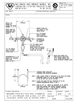
2. Oil Cooling Coil Connection
As indicated above, a cooling coil is
used to keep oil in the bearing res-
ervoir cool. Water at pressures as
high as 100 PSI is circulated
through the coil. It is imperative,
there for, that all joints be tight and
that there be no leaks. A pin-hole
leak will quickly allow enough wa-
ter to overflow into interior of motor
and cause motor failure.
Motors covered by this instruction
book are furnished with inlet and
outlet connection fittings designed
to prevent inadvertent loosening of
internal joints or undue stress on the
internal piping when external water
supply pipes are connected to the
motor.

GEK-95352
12
See Figure 4 and the following
paragraphs for further instructions.
Also see maintenance instructions.
To make water connections, simply
remove the pipe plugs (furnished for
shipping) from brass fittings B and
make connection to female pipe-
tapped hole in accordance with ap-
plicable codes and good practice.
TIGHTEN CONNECTIONS SE-
SECURELY BUT NOT EXCES-
SIVELY. It is recommended that
the upper fitting be used for inlet
and lower fitting for drain.
DO NOT LOOSEN SCREWS F OR
REMOVE PART B WHEN
CONNECTING WATER SUPPLY
TO MOTOR: PART B MUST BE
FULLY SEATED AGAINST
PART A TO COMPRESS THE
WATER/OIL SEALING O-RING.
Part A is screwed into the endshield
wall and locked with set-screws E --
when making water connection
check part A to be sure it is tight
and there are no oil leaks around it.
Since there is no solid connection
between parts A and C, inadvertent
loosening of internal connections is
minimized.
COOLING COIL CONNECTION FITTINGS
IV. OPERATION
Before energizing the motor for
the first time or after an ex-
tended shutdown, it is advis-
able to check insulation resis-
tance, power supply and me-
chanical freedom of the motor.
If the motor has been stored in a damp loca-
tion, dry it out thoroughly before operating.
Be sure that the motor is not
running and the power supply
is disconnected before working
on motor.
A. Steps Prior to Initial Start-Up or
After a Long Idle Period
1. Check insulation resistance as
indicated in the caution above.
Before measuring insulation
resistance the machine must be
at standstill and all windings to
be tested must be electrically
connected to the frame and to
ground for a time sufficient to
remove all residual electrostatic charge. Failure
to observe these precautions may result in in-
jury to personnel.
In accordance with established stan-
dards, the recommended minimum
insulation resistance for the stator
winding is as follows:
VS
R
S
=+ 1
1000
Where RS is the recommended
minimum insulation resistance in
megohms at 40º C of the entire sta-
tor winding obtained by applying di-
rect potential to the entire winding
for one minute, and VS is rated ma-
chine voltage.

GEK-95352
13
NOTE SEE IEEE RECOMMENDED
PRACTICE FOR TESTING INSU-
LATION RESISTANCE OF ROTATING
MACHINES, PUBLICATION NO. 43,
FOR MORE COMPLETE INFOR-
MATION.
If the insulation resistance is lower
than this value, it may be wet and it
is advisable to eliminate the mois-
ture in one of the following ways:
a. Dry the stator in an air circulating
oven with the air surrounding the part at
95ºC to 115ºC until the stator has been
above 90º C for at least four hours. Then
the air temperature may be raised to
135ºC to 1 15ºC. Continue to heat until
the insulation resistance is constant for a
one-half hour period.
b. Enclose the motor with canvas or
similar covering, leaving a hole at the top
for moisture to escape. Insert heating
units or lamps and leave them on until the
insulation resistance is constant for one-
half hour period. Be careful not to get
heating units so close to the winding that
they cause localized damage.
c. With the rotor locked and using ap-
proximately 10% of rated voltage, pass a
current through the stator windings. In-
crease the current gradually until the tem-
perature reaches 90ºC . Do not exceed
this temperature. Maintain a temperature
of 90ºC until the insulation resistance be-
comes constant for a one-half hour pe-
riod.
2. Check bearing oil reservoirs to
be sure they have been filled to the
proper level with fresh oil. See
RELUBRICATION, TABLE II,
and LUBE NAMEPLATE on motor
for oil grade and viscosity and fur-
ther instructions. Be sure filler caps
and drain plugs are securely tight-
ened.
3. Whenever possible, examine
the interior of the machine for loose
objects or debris which may have
accumulated, and remove any for-
eign material.
4. If possible, turn the rotor by
hand to be sure that it rotates freely.
5. Check all connections with the
connection diagram. Check all ac-
cessible factory-made connections
for tightness to make sure none has
become loose during shipment.
6. Check water-cooling connec-
tions, flow, and temperature.
7. If possible leave motor un-
coupled (or uncouple it) for initial
operation so that motor vibration,
noise, current and bearings can be
checked uncoupled before they are
masked by the pump. To run a VHS
motor uncoupled, it is recommended
that the pump head-shaft be re-
moved. If this cannot be done re-
move the upper half-coupling and
be sure the pump shaft is well cen-
tered in the motor shaft so it will not
rub. IF THIS IS DONE, ROTATE
MOTOR BY HAND TO BE SURE
THERE IS NO INTERFERENCE
BETWEEN SHAFTS. Do not try to
run motor uncoupled by just re-
moving gib-key.
8. When the driven machine is
likely to be damaged by the wrong
direction of rotation, it is imperative
to uncouple the motor from its load
during the initial start and make cer-

GEK-95352
14
tain that it rotates in the correct di-
rection. If it is necessary to change
rotation, interchange any two line
leads. For multispeed motors check
each speed independently. On VHS
motors do this before installing
pump head-shaft and upper half-
coupling.
Some motors are designed for unidi-
rectional rotation. Rotation of these
motors must be in accordance with
the rotation indicated on the name-
plate and the outline furnished with
the equipment.
B. Initial Start
1. After inspecting the machine
carefully as outlined above, make
the initial start by following the
regular sequence of starting opera-
tions in the control instructions.
2. Run the motor uncoupled ini-
tially, if possible, checking for ab-
normal noise, vibration or bearing
temperatures, and for current and
voltage balance. Then check motor
operation under load for an initial
period of at least one hour to ob-
serve whether any unusual noise or
hotspots develop.
3. In the event of excessive vi-
bration or unusual noise, remove all
power and disconnect the machine
from the load and check the
mounting and alignment.
4. Space heaters should be de-
energized during motor operation.
5. Check line voltage on all 3
phases to be sure it is balanced and
within 10% of motor rated voltage
with motor drawing load current.
6. Check the operating current
against the nameplate value. Do not
exceed the value of nameplate am-
peres X service factor (if any) under
steady continuous load. Also check
to be sure that current in all three
lines is balanced.
C. Jogging and Repeated Starts
Repeated starts and/or jogs of
induction motors greatly reduce
the life of the winding insula-
tion. The heat produced by
each acceleration or jog is
much more than that dissipated
by the motor at full load. If it is necessary to re-
peatedly start or jog a motor, it is advisable to
check the application with the local General
Electric sales office.
Check motor heating but do not de-
pend on your hand to determine
temperature. Use the temperature
detectors furnished in the motor if
there are any (eg., RTD’s or thermo-
couples), or use a thermometer. If
there is any doubt about the safe op-
erating temperature, take the tem-
perature of the part in question and
confer with the nearest sales office
of the General Electric company.
Give full details, including all
nameplate information.
Overheating of the motor may be
caused by improper ventilation, ex-
cessive ambient temperature, dirty
conditions, excessive current due to
overload, unbalanced a-c voltage, or
(if a variable speed controller is
used) harmonics in power supplied
to the motor.

GEK-95352
15
V. MAINTENANCE
Before initiating maintenance
procedures, disconnect all
power sources to the motor and
accessories. For machines
equipped with surge capacitors
do not handle capacitor until it
is discharged by a conductor simultaneously
touching
all terminals
and leads, including
ground. This discharge conductor should be
insulated for handling.
Replace all normal grounding connections prior
to operating.
Failure to observe these precautions may result
in injury to personnel.
A. General
Inspect the motor at regular intervals, as
determined by service conditions. Keep
the motor clean and the ventilation open-
ings clear.
In addition to a daily observation of the
overall condition, it is recommended that
a regular inspection routine be set up to
check periodically the following items:
1. General Cleanliness
2. Insulation and Windings
3. Lubrication and Bearings
4. Coupling Bolt Tightness
B. General Cleanliness
The interior and exterior of the machine
should be kept free from dirt, oil, grease
and conducting dust. Oily vapor, debris,
or dust may build up and block off venti-
lation. Any of these contaminants can
lead to early motor failure. Motors should
be disassembled and thoroughly cleaned
periodically as needed.
Motors may be blown out with dry, com-
pressed air of moderate pressure. How-
ever, cleaning by suction is preferred be-
cause of the possibility of water in the
compressed air lines and the danger of
blowing metal chips into the insulation
with compressed air.
To prevent injury to eyes and
respiratory organs, safety
glasses and suitable ventilation
or other protective equipment
should be used. Operator must
not use compressed air to re-
move dirt or dust from his person or clothing
.
Screens and covers are provided as neces-
sary for protection of the equipment and
personnel. All screens must be kept free
of dirt and debris to ensure proper venti-
lation, and kept in place for protection of
personnel.
C. Coupling Maintenance
The condition of non-reverse couplings
should be checked periodically by re-
moving the top cap. If dirt has caused the
action of the pins to become sluggish, the
pin-carrier should be removed, disassem-
bled, and thoroughly cleaned with a suit-
able solvent. The parts should then be
dried and reassembled in accordance with
the instructions given under NON-
REVERSE COUPLINGS.
Sometimes, after a long period of opera-
tion with frequent stops and starts, the
surface of the holes in the pin-carrier be-
comes polished, so that friction forces
will no longer hold the pins clear of the
ratchet teeth when the motor is running.
This condition can be remedied by rough-
ening these surfaces with a piece of em-
ery paper wrapped around a rod.

GEK-95352
16
NOTE: WHENEVER THE DISMAN-
TLING OF COUPLINGS IS NECES-
SARY, THE USE OF WITNESS
MARKS WILL ASSURE A BAL-
ANCED CONDITION WHEN RE-
ASSEMBLY IS COMPLETE.
Bolts on both bolted couplings and non-
reverse couplings should be checked pe-
riodically to be sure they are tight. See
recommended tightening torques.
A. Relubrication
Motors covered by these instructions have
oil lubricated bearings. Maintain proper
lubrication by checking the oil level peri-
odically and adding oil when necessary.
Because of the clearing action of the
bearing as the motor accelerates up to
speed, and the expansion of the oil as it
comes up to operating temperature, the oil
level will be higher after the motor has
been in operation for a while than it is
with the motor at standstill. The normal
level, with the motor stopped and the oil
cold, is marked STANDSTILL LEVEL
on the sight gage.
Overfilling should be avoided not only
because of the possibility that expansion
may force the oil over the oil sleeve and
into the motor, but also because operating
with the oil level too high prevents the
bearing from clearing itself of excess oil.
The resultant churning can cause extra
loss, high temperatures, and oxidized oil.
If, during operation, the oil level goes
above the maximum shown on the sight
gage, drain enough oil to bring the level
back within the operating range. A hole is
provided inside the drain plug to make it
possible to do this without completely
removing the plug.
Do not permit the operating oil level to
fall below the minimum shown on the
gage. Should it ever become necessary to
add excessive amounts of make-up oil,
investigate immediately for oil leaks.
Change oil at regular intervals. The time
between oil changes depends upon the se-
verity of operating conditions and, hence,
must be determined by the motor user.
One or two changes a year is average, but
special conditions, such as high ambient
temperature, may require more frequent
changes. Avoid operating motor with oxi-
dized oil.
Use only best grade, oxidation and corro-
sion inhibited turbine oil produced by
reputable oil companies. The viscosity
(weight) of the oil to be used depends
upon the type and size of the bearing, its
load and speed, the ambient temperature,
and the amount and temperature of the
cooling water (if used). The lubrication
nameplate or instruction with each motor
specifies the viscosity range of oil suit-
able for average conditions. The usual
recommendations are summarized in Ta-
ble 11, Oil Viscosity. Operation in ambi-
ent temperatures that are near or below
freezing may require preheating the oil or
the use of a special oil.
In some cases, water cooling for the oil is
impractical or undesirable, and the normal
operating oil temperature will be in range
of 170ºF to 210ºF. Also, in some cases
the bearing size, thrust-load and speed are
so high that even with water cooling the
normal oil temperature may be as high as
210ºF. In these cases, it is especially im-
portant that proper viscosity, high-grade
oil containing an oxidation inhibitor be
used. Observe the condition of the oil fre-
quently and change oil when it begins to
show signs of deterioration.

GEK-95352
17
TABLE II
OIL VISCOSITY
(For a particular motor, refer to the lubrication nameplate or instructions.)
Bearing Function Oil Viscosity - SUS
and Location Bearing Type
@100°F@°210 F
GE Spec
Thrust Bearing Angular Contact Ball 150 45 D6B6A
(In top endshield) Spherical Roller 600 70 D6B14C1
or 300 53 D6B6B
Guide Bearing Ball 150 45 D6B6A
(In base endshield)
Oil-lubricated bearing housings are pro-
vided with large settling chambers in
which dust, dirt, and sludge collect. Un-
less the oil has been permitted to oxidize,
the draining of the old oil during regular
changes will usually provide sufficient
flushing action to clean out the reservoir.
Whenever the motor is disassembled for
general cleaning and reconditioning, the
bearing housing may be washed out with
a suitable cleaning solvent. 1,1,1 Trichlo-
roethane may be used, following the same
instructions and cautions as shown for
cleaning windings. Avoid using any sol-
vent that will soften the paint used on the
interior of’ the oil reservoir. Be sure that
the oil metering hole is clear, and then dry
the housing thoroughly before reassem-
bly.
E. End-Play Adjustment
1. General
Most high-thrust motors are de-
signed to withstand only momentary
up-thrust. This up-thrust, which can
exist for a few seconds during
starting, is taken by the lower guide
bearing. To prevent the thrust bear-
ing from losing radial stability dur-
ing this time, the motor end-play is
limited to a small amount by ad-
justment of the motor shaft nut. This
adjustment is made at the factory
and need not be disturbed on a new
motor. However, should the motor
be disassembled for any reason, the
adjustment must be made during re-
assembly to avoid damaging the
bearings, or having some rotating
part rub against a stationary part.
The procedure depends upon the
type of thrust bearing.
2. End-Play Adjustment – Ball
Thrust Bearing
For a motor with angular-contact
ball thrust bearings, refer to Figure
1. When the motor shaft nut is tight-
ened, the rotor, shaft, and lower
bearing are drawn up until the outer
ring of the lower bearing seats
against the lower bearing cover.
Further tightening of the nut pre-
loads the bearings. (Note that shoul-
der on the shaft below the lower
half-coupling is purposely located
so that it does not seat against the
coupling.)
The best way to adjust the nut is by
trial, using an indicator between the
lower half-coupling and top end-
shield, and lifting the rotor to check
the end-play after each setting of the
nut until between 0.002 and 0.005”

GEK-95352
18
is obtained. The nut should then be
locked with its lockwasher. If
equipment is not available to use
this method, the following proce-
dure may be used. Tighten the mo-
tor shaft nut carefully until all end-
play is removed and the rotor just
fails to turn freely. Then back the
nut off 1/6 turn and lock with its
washer. An assembly nameplate
giving this information is mounted
on the motor.
Motors which must withstand con-
tinuous up-thrust have a somewhat
different construction. The upper
(thrust) bearing is arranged to take
this up-thrust; it consists of angular-
contact thrust bearing mounted
back-to-back (DB). (See Figure 3.)
The inner rings are locked on the
lower half-coupling with a nut and
the outer rings are clamped in the
endshield with a ring. The shaft
shoulder below the lower half-
coupling is so located that it seats
against the lower half-coupling be-
fore the lower bearing comes up
against its cover. No special adjust-
ment is necessary when reassem-
bling this type of motor, and the
motor shaft nut can be pulled down
tight and locked. The end-play of
motors using DB-mounted bearings
will then be very small, 0.005” or
less.
3. End-Play Adjustment
Roller-Thrust Bearing
Springs are used under spherical-
roller thrust bearing to keep them
axially loaded during momentary
up-thrust periods. See Figure 2. This
puts an up-thrust load on the lower
guide bearing. The springs (and
spacers if a full circle of spring is
not used) are located in a “chair”
which is in turn located in the upper
endshield. This ”chair” and the cap-
tive springs can be removed and
cleaned as a unit if necessary; it
should not be taken apart unless it or
a spring is damaged.
End-play is provided in the motor so
that the application of down-thrust
during normal operation will cause
the thrust bearing to move down and
seat in its housing and relieve the
up-thrust load on the lower bearing.
Thus, to avoid premature failure of
the lower bearing, the minimum to-
tal external down-thrust that is ap-
plied continuously to the motor
during operation should always be
greater than the spring-load listed on
the individual outline provided with
the motor. This value may range
from 3000 pounds to 6000 pounds,
depending on the size of the bear-
ing.
Adjust the end-play by adjusting the
motor shaft nut. Tighten the nut un-
til the lower bearing comes up
against its cover and the springs are
being compressed, as indicated by
downward movement of the lower
half-coupling. Check the end-play
by placing a dial indicator between
the end-shield cover and the lower
half-coupling and pressing down on
the latter with a jack (sec Figure 2)
until the bearing seats in its housing.
Repeat this process of tightening the
nut and checking the end-play until
0.015 to 0.020” end-play is ob-
tained; then lock the nut with the
setscrew.
There are six holes in the nut and
five holes in the lower half-
coupling, making a total of 30
“locking positions” where two holes

GEK-95352
19
line up. Turning the nut from one
locking position to the next repre-
sents a change of end-play of ap-
proximately 0.0028”.
When run uncoupled from the
pump, the motor may have exces-
sive vibration. If so, it should be
checked with zero end-play. The
thrust bearing will then be more
nearly in the position it will assume
when down-thrust is applied during
normal operation. After the check
run, set the end-play as described
previously. Do not run motors with
spherical roller thrust bearings un-
coupled for long periods because the
lower bearing may over-heat or fail
because of the up-thrust load im-
posed by the springs.
F. Bearing Replacement
In general, replacement bearings should
be of the same type, and installed in the
same relative position, as the original
bearings.
When removing bearings, apply steady,
even pressure parallel to the shaft or
lower half-coupling center-line. Apply
this pressure to the inner race whenever
possible. Angular-contact bearings which
have failed, and are especially tight on the
coupling, can sometimes be removed by
using the following procedure: separate
the bearing by forcing the outer race over
the balls; then with a torch, apply quick
heat to the inner race while also applying
pulling pressure.
Angular-contact bearings which are to be
stacked together should have their high
points of eccentricity (indicated by a bur-
nished spot on the inner race) lined up.
All bearings should be of same manufac-
ture and of the type that permits stacking.
Some motors with angular-contact ball
bearings are supplied with removable
spacer ring under the outer race of the
thrust bearing so that the thrust capacity
can be increased by adding an extra
bearing or bearings. When these bearings
are installed, the high points of eccentric-
ity should be lined up with the keyway in
the lower half-coupling. If the original
bearings have been in service, they should
be replaced at the time this conversion is
made.
G. Oil Cooling Coil Maintenance
See general description of cooling coil
connection fitting and Figure 4.
As part of ongoing preventative mainte-
nance check for oil leaks around the
cooling coil fitting, and check for possible
internal water leakage as indicated by an
unexplained rise in oil level or a change
in oil color. Parts A, B, E and F should
always be tight, and part B should always
be seated tightly against part A to ensure
that the sealing O-Ring is properly com-
pressed.
If cooling coil is to be removed, first re-
move supply pipes and drain water out of
coil. Next remove parts F, B, E and A in
that order. Then remove the endshield
cover and unscrew the inlet and outlet
pipes (part C) from the cooling coil being
careful to hold the elbows on the ends of
the cooling coil to prevent damage. Fi-
nally, remove the oil-baffle and the cool-
ing coil.
To re-install the cooling coil proceed as
follows:
1. OBTAIN A NEW O-RING
UNLESS YOU ARE CERTAIN
OLD O-RING IS UN-DAMAGED
AND HAS NOT AGED OR
TAKEN A COMPRESSION SET.

GEK-95352
20
2. Place coil (without inlet / out-
let pipes C) in endshield and secure
loosely.
3. Stick inlet-outlet pipes C
through holes in end shield wall and
check line up of pipes and end
shield holes by screwing pipes
loosely into cooling coil elbow.
Pipes should be centered in holes in
end shield wall. Adjust cooling coil
as needed but Do Not Tighten
Parts Yet.
4. Thread part A over pipes and
screw A into end shield loosely.
Adjust position of cooling coil as
necessary to let pipes exit without
strain and then secure cooling coil
into end shield.
5. Remove parts A and C and put
pipe joint compound on threads. In-
spect outer end and slots in C pipes
and remove any burrs or sharp
edges to prevent damage to O-Ring
during assembly. Then screw pipes
C hand-tight into cooling coil el-
bows, being careful not to bend or
damage the cooling coil when tight-
ening C. Next, tighten C by using
wrench on hex fitting at inner end of
C.
6. Next, slide part A into place
and screw tightly into end shield,
being careful not to damage outer
surface of C where O-Ring will seat.
7. Check gap between endshield
wall and inner surface of A. If this
exceeds 1/4", endshield hole should
be tapped deeper.
8. Check position of end of C
with respect to outer face of A. See
Figure 4 for limiting dimensions.
9. Install 3 set-screws E in A
120° apart and tighten securely to
lock A into position and keep it
from unscrewing. Set-screws should
bite into surface of endshield.
10. Be very careful not to damage
or mar outer surface of C where O-
Ring seats.
11. Re-check outer end and slot of
C and remove any burrs or sharp
edges to prevent damage to O-Ring
during assembly. Then lubricate O-
Ring and slide it into position
shown in Figure 4. Be sure to push
it in until it seats against A.
12. Slide part B into place and se-
cure with 3 socket-head screws F.
Tighten F screws until flange of B
seats solidly against A. There
should never be a gap between A
and B. Use ”Loc-Tite” on threads of
F-screws to prevent their unscrew-
ing.
Parts A and B compress the O-Ring
against C and seal oil into motor and wa-
ter into coil.
13. Pressure check entire system.
H. Insulation and Winding
Maintenance
1. General
For long life and satisfactory opera-
tion, insulated winding should be
kept clean and free of dirt, oil, metal
particles, and other contaminants. A
variety of satisfactory and accept-
able methods are available for
keeping equipment clean. The
choice of method will depend
greatly on time, availability of
/