ADC HRM-238 L1 User manual

Type
User manual

This manual is also suitable for

ADC HRM-238 L1 is a two-slot HiGain Retrofit Management shelf that can accommodate up to two HiGain management units (HMU-319s). This shelf's primary function is to manage HiGain line units and provide network management capabilities for up to 56 line units. It can be used in conjunction with either unmanaged 220-type, 3190-type, or DDM+ type mechanic shelves. With the HRM-238 L1, users can expect improved operational capabilities, flexible application options, and enhanced management cabling.

ADC HRM-238 L1 is a two-slot HiGain Retrofit Management shelf that can accommodate up to two HiGain management units (HMU-319s). This shelf's primary function is to manage HiGain line units and provide network management capabilities for up to 56 line units. It can be used in conjunction with either unmanaged 220-type, 3190-type, or DDM+ type mechanic shelves. With the HRM-238 L1, users can expect improved operational capabilities, flexible application options, and enhanced management cabling.

Product Catalog: HRM-238 L1
CLEI: T1MFW004
HRM-238 List 1 HiGain Retrofit Management Shelf
User Manual
LTPH-UM-1237-04
ii July 21, 2004 HRM-238 List 1
Revision History
To order copies of this manual, use document catalog number LTPH-UM-1237-04. (Copies of this publication
can be downloaded from the ADC website at www.adc.com. To order a hard copy, please contact your sales
representative.)
Copyright
July 21, 2004
© 2004 ADC Telecommunications, Inc. All rights reserved.
Trademark Information
ADC and HiGain are registered trademarks of ADC Telecommunications, Inc. No right, license, or interest to such trademarks
is granted hereunder, and you agree that no such right, license, or interest shall be asserted by you with respect to such
trademark.
Other product names mentioned in this document are used for identification purposes only and may be trademarks or
registered trademarks of their respective companies.
Disclaimer of Liability
Information contained in this document is company private to ADC Telecommunications, and shall not be modified, used,
copied, reproduced or disclosed in whole or in part without the written consent of ADC.
Contents herein are current as of the date of publication. ADC reserves the right to change the contents without prior notice.
In no event shall ADC be liable for any damages resulting from loss of data, loss of use, or loss of profits, and ADC further
disclaims any and all liability for indirect, incidental, special, consequential or other similar damages. This disclaimer of
liability applies to all products, publications and services during and after the warranty period.
Issue Release Date Revisions Made
1 May 9, 2003 Initial release
2 March 31, 2004 Updated Certificate and Warranty and Product Support Sections.
3 April 28, 2004 Misc technical updates
4 July 21, 2004 Misc technical updates/additions.
LTPH-UM-1237-04 Using This Manual
HRM-238 List 1 July 21, 2004 iii
USING THIS MANUAL
The following conventions are used in this manual where applicable:
Monospace type indicates screen text.
Keys you press are indicated by small icons such as or . Key combinations to be pressed
simultaneously are indicated with a plus sign as follows: + .
Items you select are in bold.
The following types of messages, identified by icons, may appear in text.
For a list of abbreviations used in this document, refer to “Appendix C - Abbreviations” on page 15.
INSPECTING SHIPMENT
Upon receipt of the equipment:
Unpack each container and inspect the contents for signs of damage. If the equipment has been damaged in
transit, immediately report the extent of damage to the transportation company and to ADC
Telecommunications, Inc. Order replacement equipment, if necessary.
Check the packing list to ensure complete and accurate shipment of each listed item. If the shipment is short
or irregular, contact ADC as described in “Appendix B - Product Support” on page 14. If you must store the
equipment for a prolonged period, store the equipment in its original container.
Notes provide information about special circumstances.
General cautions indicate the possibility of personal injury, product failure, or equipment
damage if instructions are ignored or not completely followed.
An Electrostatic Discharge (ESD) caution indicates that a device or assembly is susceptible
to damage from electrostatic discharge.
An electrical shock warning indicates the presence of a dangerous level of electrical power
and the potential for serious personal injury or equipment damage.
Y ENTER
CTRL ESC
Inspecting Shipment LTPH-UM-1237-04
iv July 21, 2004 HRM-238 List 1
LTPH-UM-1237-04 Table of Contents
HRM-238 List 1 July 21, 2004 v
TABLE OF CONTENTS
Overview ____________________________________________________________________________ 1
Features..............................................................................................................................................1
Operational Capabilities.....................................................................................................................2
Application ..........................................................................................................................2
Management Cabling...........................................................................................................4
Installation___________________________________________________________________________ 5
Inspecting Your Shipment .................................................................................................................5
Installing the HRM-238 Shelf............................................................................................................5
Installing Frame Ground and Battery Power .....................................................................................5
Installing Communication Wiring .....................................................................................................6
Connect NMA Wiring .........................................................................................................7
Connect to a LAN or Interconnect Shelves.........................................................................9
Connect to a Computer, Terminal, or Modem.....................................................................9
Identifying Alarms...........................................................................................................................11
Turning Up the System....................................................................................................................11
Insert Fuse..........................................................................................................................11
Verify Cabling...................................................................................................................12
Secure Cabling...................................................................................................................12
Installing the Management Unit(s) ..................................................................................................12
Appendix A - Specifications____________________________________________________________ 13
Appendix B - Product Support _________________________________________________________ 14
Appendix C - Abbreviations ___________________________________________________________ 15
Certification and Warranty______________________________________________ Inside Back Cover
List of Figures LTPH-UM-1237-04
vi July 21, 2004 HRM-238 List 1
LIST OF FIGURES
1. HRM-238 List 1 (front view) ........................................................................................................................ 1
2. Recommended Network Setup for 220 Type Shelves................................................................................... 2
3. Recommended Network Setup for 3190 Type Shelves................................................................................. 3
4. Recommended Network Setup for DDM+ Type Shelves ............................................................................. 3
5. HRM-238 Shelf Backplane Connectors (back view) .................................................................................... 4
6. Shelf with Brackets Positioned for 19-inch Rack.......................................................................................... 5
7. Connect -48 Vdc and Frame Grounds to TB1............................................................................................... 6
8. Connect NMA Wiring ................................................................................................................................... 7
9. Using BNC Connector................................................................................................................................... 9
10. AUX or OS Connectors................................................................................................................................. 9
11. Alarm Relay Wire-Wrap Pins...................................................................................................................... 11
LTPH-UM-1237-04 List of Tables
HRM-238 List 1 July 21, 2004 vii
LIST OF TABLES
1.HRM-238 Connectors ......................................................................................................................................4
2.Terminal Block (TB1)......................................................................................................................................6
3.P1 and P6 NMA Connectors ............................................................................................................................8
4.BNC Connector J1 and J3 ................................................................................................................................9
5.AUX P3 and P5 Connectors...........................................................................................................................10
6.OS Port P2 and P4..........................................................................................................................................10
7.Alarm J13 and J14 Pinouts.............................................................................................................................11
List of Tables LTPH-UM-1237-04
viii July 21, 2004 HRM-238 List 1
LTPH-UM-1237-04 Overview
HRM-238 List 1 July 21, 2004 1
OVERVIEW
The HiGain
®
HRM-238 List 1 is a two-slot HiGain Retrofit Management (HRM) shelf. This shelf fits into either
a 19- or 23-inch Central Office (CO) equipment rack. It accommodates up to two HiGain management units
(HMU-319s). It is used in conjunction with 220-type, unmanaged 3190 type, and DDM+ type mechanic shelves
to manage HiGain line units.
The HRM-238 shelf, with two management units installed, provides network management capabilities for a
maximum of 56 HiGain line units (one 3190 or DDM+ or two 220 shelves). Each management unit in the
HRM-238 shelf can manage up to 28 line units.
The HMU-319 management unit installs horizontally into the 4 ¾-inch slots labeled A or B on the HRM-238 shelf
(Figure 1). Each management unit connects to the shelf backplane through a 96-pin DIN connector.
Figure 1. HRM-238 List 1 (front view)
FEATURES
Standard features include:
50-pin Amp-type connectors for connection between the management units in the HRM-238 shelf and
previously unmanaged HiGain line units in 220, 3190, or DDM+ mechanics shelves.
DB-25 connectors for connection to a computer, terminal, or modem
British Naval Connector (BNC) for connection to a Local Area Network (LAN) or to a HMU-319 multi-shelf
connection
screw-type terminals for -48 Vdc power connection and grounding
23 wire-wrap pins to monitor alarm relay activity
AB
96-pin DIN
connector (J2)
96-pin DIN
connector (J4)
H0543-A
Overview LTPH-UM-1237-04
2 July 21, 2004 HRM-238 List 1
OPERATIONAL CAPABILITIES
Application
With two HMU-319 management units installed, the HRM-238 shelf provides network management for up to 56
HiGain line units.
Recommended Network Setup for 220 Type Shelves
The configuration shown in Figure 2 is the recommended setup for 220 type mechanics shelves. Position the
HRM-238 shelf between the 220 type shelves, with up to two 220-type shelves above and two below. This limits
the distance for the wire leads between the connectors for the management units and the line units they manage.
Figure 2 shows the HRM-238 shelf from the rear view with the A-side connectors on the right and the B-side
connectors on the left. The leads from the HRM-238 shelf connector attach to the Network Management Agent
(NMA) pins on the rear of the 220-type mechanics shelves for each line unit managed. The NMA pin on 220 type
chassis is pin 46.
Figure 2. Recommended Network Setup for 220 Type Shelves
HCS-417/418
HCS-417/418
HCS-417/418
HCS-417/418
HRM-238
-48V A
-48V A
-48V A
-48V A
-48V B
-48V B
-48V B
-48V B
NMA 1 to 14 B
NMA 15 to 28 B
NMA 1 to 28 B
NMA 1 to 14 A
Network B Network A
TB1
CO -48V
Supply
NMA 15 to 28 A
NMA 1 to 28 A
H0544-B
LTPH-UM-1237-04 Overview
HRM-238 List 1 July 21, 2004 3
Recommended Network Setup for 3190 Type Shelves
The configuration shown in Figure 3 is the recommended setup for 3190 type mechanics shelves. Position the
HRM-238 shelf below the 3190 type shelves. This limits the distance for the wire leads between the connectors
for the management units and the line units they manage. Figure 3 shows the HRM-238 shelf from the rear view
with the A-side connectors on the right and the B-side connectors on the left. The leads from the HRM-238 shelf
connector attach to the Network Management Agent (NMA) pins on the rear of the 3190-type mechanics shelves
for each line unit managed. The NMA pin on 3190 type chassis is pin 7.
Figure 3. Recommended Network Setup for 3190 Type Shelves
Recommended Network Setup for DDM+ Type Shelves
The configuration shown in Figure 4 is the recommended setup for DDM+ type mechanics shelves. Position the
HRM-238 shelf below the DDM+ type shelves. This limits the distance for the wire leads between the connectors
for the management units and the line units they manage. Figure 4 shows the HRM-238 shelf from the rear view
with the A-side connectors on the right and the B-side connectors on the left. The leads from the HRM-238 shelf
connector attach to the Network Management Agent (NMA) pins on the rear of the DDM+ type mechanics shelves
for each line unit managed. The NMA pin on DDM+ type chassis is pin 104.
Figure 4. Recommended Network Setup for DDM+ Type Shelves
3190
HRM-238
-48V A
-48V A
-48V B
-48V B
Network B Network A
TB1
CO -48V
Supply
H0544-C
3190
NMA 1 to 28 B
NMA 1 to 28 A
NMA 1 to 28 B
NMA 1 to 28 A
DDM+
HRM-238
-48V A
-48V A
-48V B
-48V B
Network B Network A
TB1
CO -48V
Supply
H0544-D
DDM+
NMA 1 to 28 B
NMA 1 to 28 A
NMA 1 to 28 B
NMA 1 to 28 A
Overview LTPH-UM-1237-04
4 July 21, 2004 HRM-238 List 1
Management Cabling
Figure 5 shows the location for each connector on the HRM-238 shelf backplane. Table 1 lists the shelf connector
types and management functions available to the HMU-319 management units through those connectors.
Figure 5. HRM-238 Shelf Backplane Connectors (back view)
Table 1. HRM-238 Connectors
Connector Purpose Type Gender
No. of
Pins
P1, P6 Provides connection from the HRM-238 shelf for the management
units to each individual card that they manage.
Amphenol
(CHAMP)
Male 50
P2, P3, P4, P5 Provides 4 connection points (two for each management unit) for a
terminal, computer, or modem. There is one AUX port and one OS port
connector for each management unit.
DB-25 Female 25
TB1 Provides separate -48 Vdc connection from the CO battery source
to each management unit. Also provides battery common ground and
a frame ground.
Terminal
block
N/A 6
J13, J14 Provides connection for alarm relay contacts. Wire-wrap
pins
Male 23
J1, J3 Provides a 10BASE-2 connection to a LAN. BNC Female 1
AUX port DB-25
connector (P5)
OS port DB-25
connector (P4)
BNC connector (J1
)
Alarm relay pins (J13)Terminal block (TB1)Alarm relay pins (J14) BNC connector (J3)
OS port DB-25
connector (P2)
50-pin Amphenol
connector (P6)
AUX port DB-25
connector (P3)
B
-s
id
e connectors
A
-s
id
e connectors
50-pin Amphenol
connector (P1)
H0545-A
LTPH-UM-1237-04 Installation
HRM-238 List 1 July 21, 2004 5
INSTALLATION
INSPECTING YOUR SHIPMENT
Upon receipt of the equipment:
Unpack each container and inspect the contents for signs of damage. If the equipment has been damaged in
transit, immediately report the extent of damage to the transportation company and to ADC
Telecommunications, Inc. Order replacement equipment, if necessary.
Check the packing list to ensure complete and accurate shipment of each listed item. If the shipment is short
or irregular, contact ADC as described in “Appendix B - Product Support” on page 14. If you must store the
equipment for a prolonged period, store the equipment in its original container.
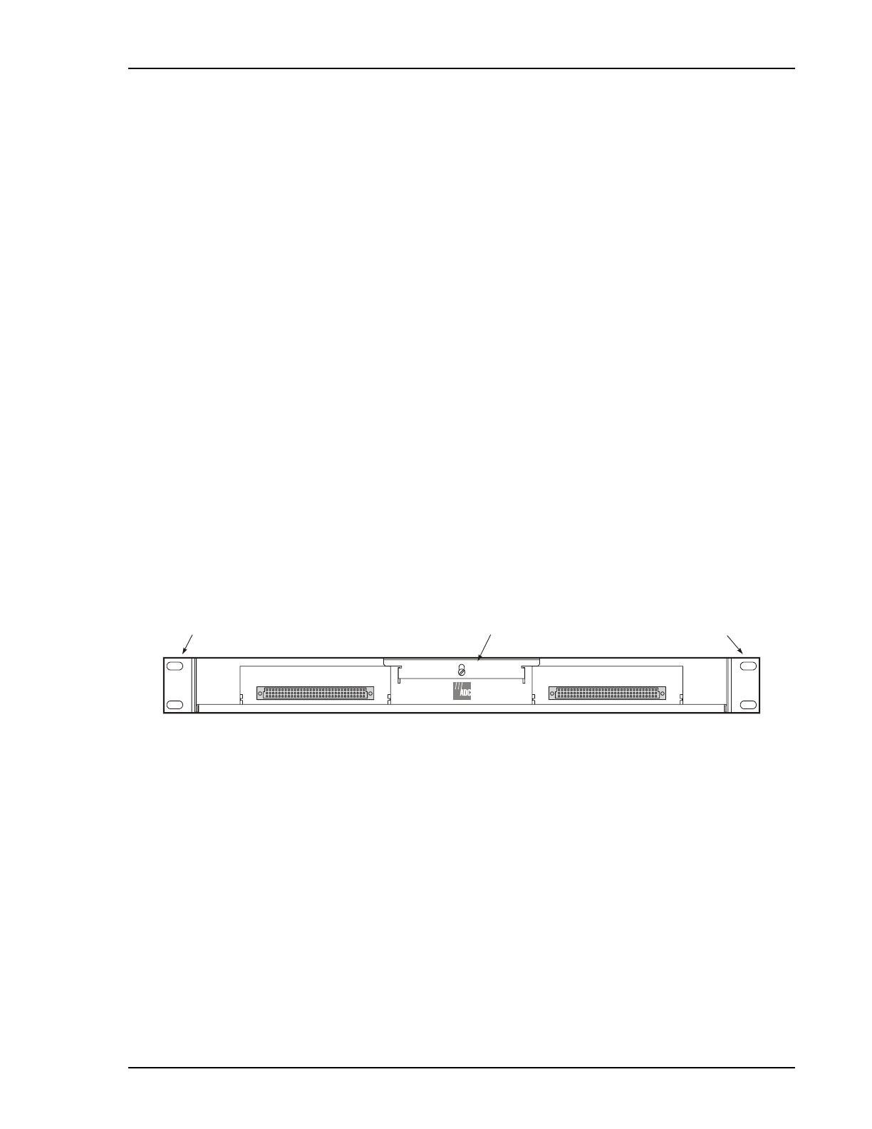
INSTALLING THE HRM-238 SHELF
Install the HRM-238 in a CO equipment bay rack. If the CO rack is 19 inches wide, attach the short side of the
mounting bracket to the HRM-238 shelf and use the long side of the mounting bracket to attach to the CO rack.
If the CO rack is 23 inches wide, reverse the mounting bracket. Attach the long side of the mounting bracket to
the HRM-238 shelf and use the short side of the mounting bracket to attach to the CO rack (Figure 6).
1 Position the HRM-238 shelf in the CO rack. (See “Operational Capabilities” on page 2, and Figure 2 on
page 2, Figure 3 on page 3, or Figure 4 on page 3 for recommended placement.)
2 Align the HRM-238 shelf mounting brackets with the vertical mounting holes on the CO rack (Figure 6).
3 Install the mounting hardware and secure.
Figure 6. Shelf with Brackets Positioned for 19-inch Rack
INSTALLING FRAME GROUND AND BATTERY POWER
Perform the following steps to install the -48 Vdc battery to the HRM-238 shelf and to connect battery common
ground (LGND) and frame ground (FGND). The HRM-238 shelf terminal block TB1 has two connection points
for supplying redundant battery capability. Connect a -48 Vdc battery source to Terminal 1 (-48V_A) to supply
voltage to the HRM-238 shelf (Table 2 on page 6). Connect another -48 Vdc battery source to Terminal 2
(-48V_B) to supply redundant voltage to the HRM-238 shelf. See Table 2 on page 6 for TB1 terminal block
information.
AB
Mounting bracket
H0546-B
Mounting bracket
S
ecurity bracket
Installation LTPH-UM-1237-04
6 July 21, 2004 HRM-238 List 1
1 Remove the fuse(s) in the equipment bay fuse panel for the circuit(s) where the HRM-238 shelf battery
wire(s) will terminate.
2 Connect one end of the frame ground wire to Terminal 4 (FGND) on TB1 of the HRM-238 shelf and attach
the other end of the frame ground wire to the CO ground wire termination point.
3 Connect the -48 Vdc CO battery to the HRM-238 shelf (Figure 7):
a Connect a wire to the HRM-238 shelf TB1 Terminal 1 (-48V_A) for Primary CO battery.
b Connect a wire to the HRM-238 shelf TB1 Terminal 2 (-48V_B) for Redundant CO battery.
c Connect the battery common wire to HRM-238 shelf TB1 Terminal 3 (BATTERY RETURN) of the
HRM-238 shelf and attach the other end to CO battery ground source(s).
d Connect the wire(s) from the HRM-238 TB1 Terminal 1 and Terminal 2 to the CO -48 Vdc power
termination point(s).
Figure 7. Connect -48 Vdc and Frame Grounds to TB1
INSTALLING COMMUNICATION WIRING
All wiring and connections for the HRM-238 shelf are on the back. Figure 5 on page 4 shows the shelf backplane
and connectors. Connect the NMA wiring from the HRM-238 shelf to each HiGain or Megabit Modem line unit
that will be managed using the steps beginning on page 7. Then, use the other connectors in “Connect to a LAN
or Interconnect Shelves” on page 9 and “Connect to a Computer, Terminal, or Modem” on page 9 that are
appropriate for your application.
Table 2. Terminal Block (TB1)
Terminal Description
1 -48V_A
2 -48V_B
3 BATTERY RETURN
4 FGND
Terminal 1
to -48 Vdc
H0547-B
Terminal 4 to
frame ground (FGND
)
Terminal 2
to -48 Vdc
Terminal 3 to battery
common (Battery Return)
LTPH-UM-1237-04 Installation
HRM-238 List 1 July 21, 2004 7
Connect NMA Wiring
From the 50-pin Amphenol connector P1 and/or P6 (Figure 8), wire directly to the NMA pin 46 on the 220-type
shelf backplane for each line unit being managed. Route wires from the P1 and P6 connectors to the NMA
220-type mechanics shelves as shown in Figure 2 on page 2. Refer to Table 3 for P1 and P6 NMA connector
information.
Figure 8. Connect NMA Wiring
1 Remove the plastic cover from the 50-pin Amphenol connector P1 and/or P6.
2 Install a 50-pin female plug into the connector. Separate the wires for each of the 50 pins.
For 220 type mechanics:
3 Wire wrap the corresponding NMA wire from the plug to the NMA pin 46 on the shelf for each line unit being
managed. The wire leads from the Amphenol plug can be up to 20 feet maximum.
For 3190 type mechanics:
4 Wire wrap the corresponding NMA wire from the plug to the NMA pin 7 on the shelf for each line unit being
managed. The wire leads from the Amphenol plug can be up to 20 feet maximum.
For DDM+ type mechanics:
5 Wire wrap or soldier (depending on chassis manufacturer) the corresponding NMA wire from the plug to the
NMA pin 104 on the shelf for each line unit being managed. The wire leads from the Amphenol plug can be
up to 20 feet maximum.
50-pin Amphenol
connector (P6)
50-pin Amphenol
connector (P1)
H0548-A
Installation LTPH-UM-1237-04
8 July 21, 2004 HRM-238 List 1
Table 3. P1 and P6 NMA Connectors
Pin Description Pin Description
26 NMA_1 1 NMA_2
27 NMA_3 2 NMA_4
28 NMA_5 3 NMA_6
29 NMA_7 4 NMA_8
30 NMA_9 5 NMA_10
31 NMA_11 6 NMA_12
32 NMA_13 7 NMA_14
33 NMA_15 8 NMA_16
34 NMA_17 9 NMA_18
35 NMA_19 10 NMA_20
36 NMA_21 11 NMA_22
37 NMA_23 12 NMA_24
38 NMA_25 13 NMA_26
39 NMA_27 14 NMA_28
40 F_ALAM 15 ERR_ALM
41 LOS_ALM 16 GND
42 GND 17 GND
43 GND 18 GND
44 GND 19 GND
45 GND 20 GND
46 GND 21 GND
47 GND 22 GND
48 GND 23 GND
49 N/C 24 N/C
50 N/C 25 N/C
LTPH-UM-1237-04 Installation
HRM-238 List 1 July 21, 2004 9
Connect to a LAN or Interconnect Shelves
Use the BNC connector (Figure 9) when required for access using a LAN or for interconnecting multiple shelves.
Consult the appropriate user manual for the HMU-319 management unit and for the software used in the
application. See Table 4 for information on BNC connector J1 and J3.
Figure 9. Using BNC Connector
Connect to a Computer, Terminal, or Modem
The AUX and OS connectors (Figure 10) are DB-25, configured as Data Terminal Equipment (DTE). There is
one AUX and one OS connector for each of the two management unit slots. Use these connectors for a direct
connection (straight-through) with devices configured Data Communication Equipment (DCE) such as modems,
X.25 Packet Assembler/Disassemblers (PADs), or LAN terminal servers.
Figure 10. AUX or OS Connectors
Table 4. BNC Connector J1 and J3
Shield LAN-, CDS
Center LAN+
BNC connector (J1)BNC connector (J3)
H0549-A
AUX port DB-25
connector (P5)
OS port DB-25
connector (P4)
OS port DB-25
connector (P2)
AUX port DB-25
connector (P3)
H0550-A
Installation LTPH-UM-1237-04
10 July 21, 2004 HRM-238 List 1
Use a null modem connector for cross-over cabling when attaching a device that is not configured as DCE (such
as terminals or computers running terminal emulation software) to these connectors. Table 5 shows the pinouts
for the two AUX ports (one port for each management unit). Table 6 shows the pinouts for the two OS ports (one
port for each management unit).
Table 5. AUX P3 and P5 Connectors
Pin Description I/O Pin Description I/O
1 N/C 14 N/C
2 AUX_TX O 15 N/C
3 AUX_RX I 16 N/C
4 N/C 17 N/C
5 N/C 18 N/C
6 AUX_DSR- I 19 N/C
7 LGND I 20 AUX_DTR- O
8 N/C 21 N/C
9 N/C 22 N/C
10 N/C 23 N/C
11 N/C 24 N/C
12 N/C 25 N/C
13 N/C
Table 6. OS Port P2 and P4
Pin Description I/O Pin Description I/O
1 N/C 14 N/C
2 OS_TX O 15 OS_TCLK I
3OS_RX I 16N/C
4 OS_RTS- O 17 OS_RCLK I
5 OS_CTS- I 18 N/C
6OS_DSR- I 19N/C
7 LGND I 20 OS_DTR- O
8 N/C 21 N/C
9 N/C 22 N/C
10 N/C 23 N/C
11 N/C 24 OS_TCLK I
12 N/C 25 N/C
13 N/C
For further details about connecting to the AUX or OS connectors, consult the appropriate user
manual for the management unit and applicable software.
LTPH-UM-1237-04 Installation
HRM-238 List 1 July 21, 2004 11
IDENTIFYING ALARMS
Alarm relay contacts for each management unit are on J13 and J14 (Figure 11). Install wiring between these pins
and an alarm monitoring device per local practice. Table 7 describes the alarm J13 and J14 pinouts.
Figure 11. Alarm Relay Wire-Wrap Pins
TURNING UP THE SYSTEM
Perform the following procedures prior to installing the management unit(s) into the shelf.
Insert Fuse
Insert an appropriately sized fuse(s) into the equipment bay fuse panel for the circuit(s) where the HRM-238 shelf
battery wire(s) were terminated. Refer to the appropriate management unit user manual for power consumption,
power dissipation, and current drain.
Table 7. Alarm J13 and J14 Pinouts
Pin Description Pin Description
1 CRIT_AUD_NC_A 13 MIN_AUD_NC_A
2 CRIT_AUD_COM_A 14 MIN_AUD_COM_A
3 CRIT_AUD_NO_A 15 MIN_AUD_NO_A
4 CRIT_VIS_NC_A 16 MIN_VIS_NC_A
5 CRIT_VIS_COM_A 17 MIN_VIS_COM_A
6 CRIT_VIS_NC_A 18 MIN_VIS_NO_A
7 MAJ_AUD_NC_A 19 SYS_ID_NC_A
8 MAJ_AUD_COM_A 20 SYS_ID_COM_A
9 MAJ_AUD_NO_A 21 SYS_ID_NO_A
10 MAJ_VIS_NC_A 22 EXT_ACO_A
11 MAJ_VIS_COM_A 23 LGND
12 MAJ_VIS_NO_A
Alarm relay pins (J13)Alarm relay pins (J14)
H0651-A
Installation LTPH-UM-1237-04
12 July 21, 2004 HRM-238 List 1
Verify Cabling
Verify the following:
1Verify a minimum of -42 Vdc and a maximum of -56 Vdc between the following:
a -48 Vdc battery screw Terminal 1 and the battery common Terminal 3 (BATTERY RETURN)
b -48 Vdc battery screw Terminal 2 (when used) and the battery common Terminal 3 (BATTERY
RETURN)
2 Visually verify that all connections are securely terminated.
Secure Cabling
Tie the cable connectors to the back of the HRM-238 shelf using the tie wraps and mounting screws.
INSTALLING THE MANAGEMENT UNIT(S)
1 Install the management unit(s) into the HRM-238 shelf per procedures in the appropriate HMU-319 user
manual.
2 Loosen the security bracket screw, push down the security bracket, and re-tighten the screw (Figure 6 on
page 5).
  • Page 1 1
  • Page 2 2
  • Page 3 3
  • Page 4 4
  • Page 5 5
  • Page 6 6
  • Page 7 7
  • Page 8 8
  • Page 9 9
  • Page 10 10
  • Page 11 11
  • Page 12 12
  • Page 13 13
  • Page 14 14
  • Page 15 15
  • Page 16 16
  • Page 17 17
  • Page 18 18
  • Page 19 19
  • Page 20 20
  • Page 21 21
  • Page 22 22
  • Page 23 23
  • Page 24 24
  • Page 25 25
  • Page 26 26

ADC HRM-238 L1 User manual

Type
User manual
This manual is also suitable for

ADC HRM-238 L1 is a two-slot HiGain Retrofit Management shelf that can accommodate up to two HiGain management units (HMU-319s). This shelf's primary function is to manage HiGain line units and provide network management capabilities for up to 56 line units. It can be used in conjunction with either unmanaged 220-type, 3190-type, or DDM+ type mechanic shelves. With the HRM-238 L1, users can expect improved operational capabilities, flexible application options, and enhanced management cabling.

Ask a question and I''ll find the answer in the document

Finding information in a document is now easier with AI