DreamLine DL-6192R-01 Installation guide

Type
Installation guide
QWALL 5 & SlimLine Shower Base Kit
ACRYLIC SHOWER WALL AND
S
HOWER
B
ASE
K
IT
I
NSTALLATION
INSTRUCTIONS
IMPORTANT
DreamLine
TM
reserves the right to alter, modify or redesign products at any time
without prior notice. For the latest up-to-date technical drawings, manuals or any
other details please refer to the support.BathAuthority.com
web page.
STEP 1: Install Shower Base
Shower Base Installation Instructions
STEP 2: Install Shower Backwalls
Shower Backwalls Installation Instructions
Please read these instructions carefully before installing. If you have any questions regarding
installation, please call our technical support specialists Monday through Friday 9:00 AM 5:00
PM EST at Phone:
1-866-731-2244, Fax: 1-866-227-1533 or e-mail our technical support
group at
support@BathAuthority.com.
For more information on DreamLine Shower Kit please visit www.BathAuthority.com
Ver. 1, Rev. 1
QWALL
5.2 (2 Back Panels)
SHOWER ACRYLIC WALL INSTALLATION INSTRUCTIONS
IMPORTANT
DreamLine
TM
reserves the right to alter, modify or redesign products at any time
without prior notice. For the latest up-to-date technical drawings, manuals or any
other details please refer to the support.BathAuthority.com
web page.
Please read these instructions carefully before installing. If you have any questions
regarding installation, please call our technical support specialists Monday through
Friday 9:00 AM – 5:00 PM EST at Phone: 1-866-731-2244
, Fax: 1-866-227-1533 or
e-mail our technical support group at
For more information on DreamLine
TM
Shower Back Wall please visit www.BathAuthority.com
Ver. 1, Rev. 1
2
Preparation
1. After opening all boxes and packages, read this introduction carefully. Check that all of
the needed parts are included in the package by marking all the components on the
“Detailed Diagram of Shower Door Components”. Examine boxes and packages for
shipping damage. If the unit has been damaged, has a finishing defect, or has missing
parts, please contact our customer support department within 5 business days of the
delivery date. Please note that DreamLine
TM
will not replace any damaged products or
missing parts free of charge after 5 business days or if the product has been
installed. Feel free to contact DreamLine
TM
if you have any questions.
2. Please note that you should consult your local building codes with questions on
installation compliance standards. Building and plumbing codes may vary by
location, and DreamLine is not responsible for code compliance standards for your
project.
3. This acrylic wall system is specially designed to be installed over any solid surface. If you
are installing the acrylic walls over existing tiles, remove all loose tiles before the
installation. If you are installing over existing painted walls, remove any loose paint. Please,
note that some cutting and drilling may be necessary during the installation process.
4. Make sure to turn off the water supply, remove faucet, handles or any fixture trims
protruding from the wall. Clean the surface, removing any soap film and dirt from all wall
surfaces using regular household detergent, and then wipe dry.
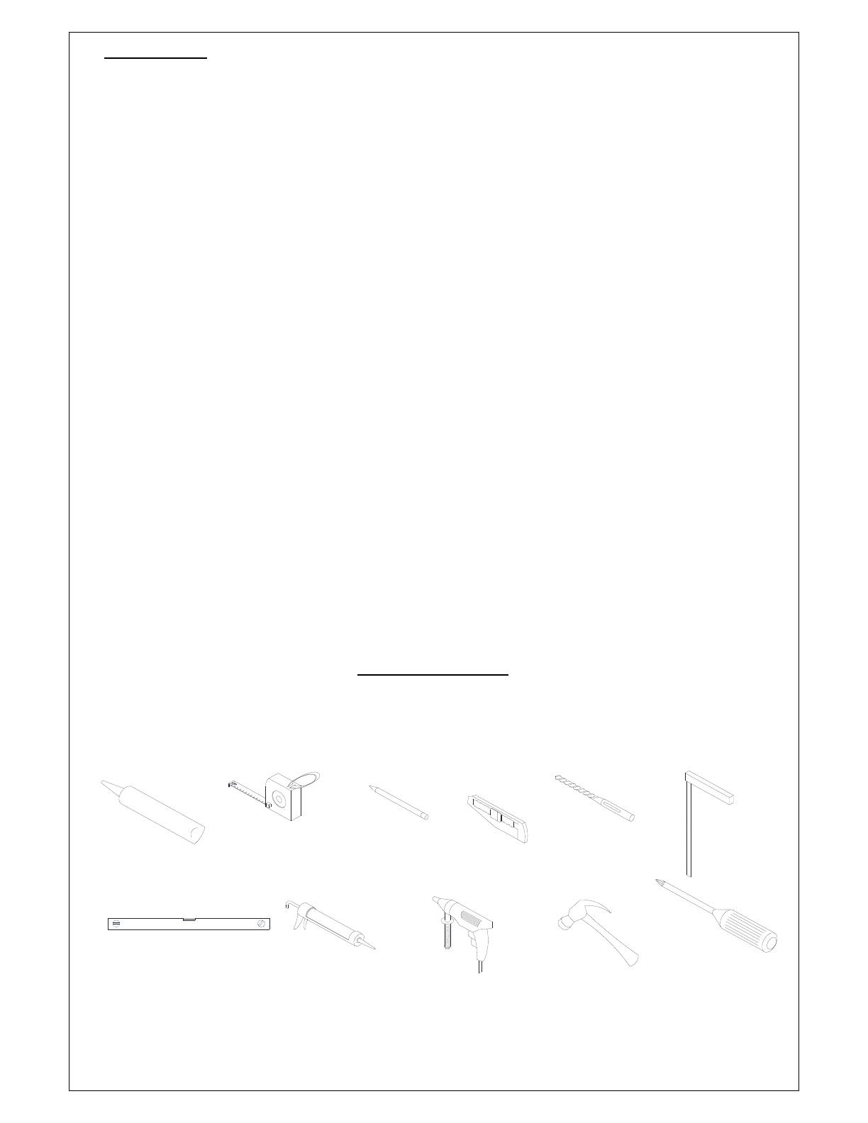
Tools Required
Caulk
Tape
Measure Pencil
Screwdriver
Phillips
(Ø 5/16")
Drill bit
Level
Gun
Caulk
Drill
Electric
Hammer
Knife
T-Square
Ver. 1, Rev. 1
3
Detailed Diagram of Acrylic Shower Wall Components
10
9
5
8
"
-
6
2
"
4
6
"
-
50
"
5
6
7
8
4
2
1
3
Packing List
01 Side panel 2pcs
06 Wall anchor 21pcs
02 Corner cover 2pcs
07 Countersunk screw ST4.2×30 21pcs
03 Decorative edge molding 2pcs
08 Decorative cover 15pcs
04 Shelf bracket 6pcs
09 Back panel 2pcs
05 Glass shelf 2pcs
10 Center cover 1pc
NOTE: Unpack your unit carefully and inspect it. Lay it out and identify all parts using the
detailed diagram and packing list in your manual as a reference. Before discarding the carton,
check for small hardware bags that tend to fall to the bottom of the box. If any parts are
damaged or missing, please contact DreamLine
TM
for replacement.
NOTE:
Retain these installation instructions for future reference.
Ver. 1, Rev. 1
4
Preparation for Installation of Back Panel
1. Place a mark on the walls at a distance of
1” (one inch) from the corner and draw
a plumb vertical line from top to bottom.
See Fig. 1 for details.
NOTE:
Repeat this step for both corners.
Fig. 1
2. The Shower back wall kit has two
Back Panels (09).
Measure the back wall of the shower
between the vertical lines you marked
in Step 1
.
This distance is marked as “W”.
See Fig. 2 for details.
Fig. 2
W
1"
1"
1
2
Ver. 1, Rev. 1
5
3. Divide the measurement “W” by two
and place a mark in the center of the
back wall and from there draw a
plumb vertical line from top to
bottom.
This distance is shown as “W/2”.
See Fig. 3 for details.
Fig. 3
4. Determine the position of both Back
panels (09).
NOTE:
a) The Narrow side (2-3/4”) of the Back
panel cannot be trimmed and should face
the center of the back wall (as shown)
b) The Wide side (3-1/8”) of the Back panel
must be trimmed to the size of the back
wall if necessary, and should face the
corner.
See Fig. 4 for details.
Fig. 9
Fig. 4
W
/
2
W
/
2
3
1
/
8
"
2
3
/
4
"
2
3
/
4
"
3
1
/
8
"
Ver. 1, Rev. 1
6
5. Measure the Back Panel (09).
Width of the Back Panel has to be less than or
equal to the distance between the center line
and the corner line on the back wall in Step. 3
L W/2
If the width of the Back Panel is greater than
the distance between the center line and the
corner line on the back wall in Step. 3
, you have
to trim the Back Panel to fit your measurement.
See Fig. 5 for details.
Fig. 5
6. Measure from the narrow edge of the
Back panel (09) and place a mark at a
distance of "W/2" (that you measured
in Step. 3
),
From this mark, draw a straight line
from top to bottom along the wide
edge of the Back panel.
See Fig. 6 for details.
Fig. 6
L
L
W
/
2
W
/
2
to cut
Line
to cut
Line
Ver. 1, Rev. 1
7
7. Place the Back Panel (09) onto a flat piece of
plywood or particle board. Use a sharp industrial
knife and a T-square to score along the marked side
ends of the Back panel and continue scoring until
you have fully cut through the panel.
See Fig. 7 and Fig. 8 for details.
Fig. 7
Fig. 8
1
2
W
/
2
W
/
2
Ver. 1, Rev. 1
8
Preparation for Installation of Side Panels
ATTENTION:
See Fig. 9 for details.
Fig. 9
8. Measure the side walls of the shower
from the 1” (one inch) line in the corner
(from Step. 1
) to the distance where you
want Side panels (01) to end.
The distance is “D”.
See Fig. 10 for details.
Fig. 10
If you are installing a shower door with a wall profile,
you can hide the edge of the Side panel (01) behind
the wall profile.
D
D
1
2
Wall Profile
Side Panel
Wall
Side Panel
Wall Profile
Wall
Ver. 1, Rev. 1
9
9. Determine the position of both
Side panels (01).
NOTE:
a) The narrow edge of the Side
panel fits behind the corner
cover and cannot be trimmed.
b) The wide edge of the Side
panel can be trimmed to the
size of your measurements
from Step. 8
.
Measure from the narrow edge of
the Side panel and place a mark
at a distance of "D" (that you
measured in Step. 8
).
Draw a straight line from top to
bottom along the wide edge of
the Side panel.
See Fig. 11 for details.
Fig. 11
10. Place the Side panel (01) on a flat piece of plywood
or particle board. Use a sharp industrial knife and a T-
square to score along the marked wide ends of the
Side panel and continue scoring until you have fully
cut through the panel.
See Fig. 12 and Fig. 13 for details.
Fig. 12
1
2
D
D
to cut
Line
to cut
Line
Ver. 1, Rev. 1
10
Fig. 13
11. Take exact measurements of the
fixture on the wall:
from the 1” (one inch) line
in the corner of the shower
to the fixture: (A, B, C)
from the bottom of the wall
of the shower to the fixture:
(E, F).
See Fig. 14 for details.
Fig. 14
D
D
D
A
F
E
1"
B
C
Ver. 1, Rev. 1
11
12. Determine which Side panel (01) will be installed on
the side wall with the fixture.
Mark the fixture location on the Side panel according
to the measurements taken in Step. 11
.
See Fig. 15 for details.
Fig. 15
13. Drill the holes for the fixtures in the Side panel (01) using
the proper diameter saw bit or a handheld jig saw.
See Fig. 16 for details.
Fig. 16
D
F
E
A
B
C
D
Ver. 1, Rev. 1
12
Acrylic Back Panel and Side Panel Installation Instruction
14. Attach the Center cover (10)
vertically at the center point along
the line (from Step. 3
) and mark the
drilling holes through the predrilled
holes in the Center cover.
Drill the holes using Ø5/16” drill bit
and insert the Wall Anchors (06).
See Fig. 17 for details.
Fig. 17
15. Mount the Center cover (10) to the centerline of the
back wall using the Countersunk screws ST4.2×30
(07). Do not fully tighten the screws at this time; leave
them loose for further installation.
See Fig. 18 and Fig. 19 for details
Fig. 18
1
2
3
4
Ø5/16"
1
2
Ver. 1, Rev. 1
13
Fig. 19
16. Attach the Corner cover (02) to
the corner of the shower and mark
the drilling holes through the
predrilled holes in the Corner
cover.
Move aside the Corner cover,
Drill the holes using Ø5/16” drill
bit and insert the Wall Anchors
(06).
See Fig. 20 and Fig. 21 for details
Fig. 20
W
/
2
W
/
2
1
2
34
Ø5/16"
Ver. 1, Rev. 1
14
Fig. 21
ATTENTION:
17. Apply the sealant to the entire surface
of the reverse side of the Back panel
(09).
See Fig. 22 for details.
Fig. 22
Installation of all Acrylic panels must
be finished before the sealant sets
for easy leveling and adjustments.
W
/
2
W
/
2
W
/
2
W
/
2
Ver. 1, Rev. 1
15
18. Slide the right edge of the left Back panel (09) all the way
behind the Center cover (10) and push the Back panel against
the wall.
Slide the left edge of the right Back panel (09) all the way
behind the Center cover (10) and push the Back panel against
the wall as well.
You can adjust the position of the Back panels before the
sealant sets.
Apply equal pressure to the whole surface of the Back panels
from top to bottom.
See Fig. 23 and Fig. 24 for details.
Fig. 23
Fig. 24
1
2
3
Ver. 1, Rev. 1
16
19. Mount the Corner cover
(02) to the corner of the
shower using the
Countersunk screws
ST4.2×30 (07).
Do not fully tighten the
screws at this time; leave
them loose for further
installation.
See Fig. 25 for details
Fig. 25
20. Apply the sealant to the entire surface of the
reverse side of the Side panel (01).
Also, apply the sealant around the drilled
holes.
See Fig. 26 for details.
Fig. 26
1
2
3
4
Ver. 1, Rev. 1
17
21. Slide the narrow edge of the Side
panel (01) behind the Corner
cover (02).
Align trimmed edge of the Side
panel (from Step. 9)
with the
marked line on the wall (in Step. 7)
and push the Side panel against
the wall.
NOTE:
Make sure the drilled holes on the
Side panel are also aligned with
the fixtures on the wall.
See Fig. 27 for details.
Fig. 27
22. Apply sealant to the entire surface of
the reverse side of the other Side
panel (01).
See Fig. 26 for details.
Slide the narrow edge of the other
Side panel (01) behind the Corner
cover (02).
Align trimmed edge of the Side panel
(from Step. 9)
with the marked line on
the wall (in Step. 7)
and push the Side
panel against the wall.
Align the top of both Side panels and
the Back panel before the sealant sets.
Apply equal pressure to the whole
surface of the Acrylic panels from top
to bottom.
See Fig. 28 for details.
Fig. 28
1
2
1
2
Ver. 1, Rev. 1
18
23. Once all panels are aligned, fasten tight the Corner
cover (02) to secure the Side panels (01) and Back
panels (09).
Cover the screw holes with the Decorative covers
(08).
See Fig. 29 for details.
Fig. 29
24. Fasten tight the Center cover (10) to secure the Back
panels (09).
Cover the screw holes with the Decorative covers
(08).
See Fig. 30 for details.
Fig. 30
1
2
1
2
Ver. 1, Rev. 1
19
ATTENTION;
Prior to the next step, please be sure the part of
the wall for installation of the Decorative edge
molding (03) is clean, dry and free from soap, oil
and any construction debris.
25. Gently remove the plastic tape from the adhesive side
of the Decorative edge molding (03) and firmly
press it to the edge of the Side panel (01) from top to
bottom.
See Fig. 31 for details.
Fig. 31
26. Apply caulk along the top edges of
the Side panels (01) and the Back
panels (09).
Apply caulk along the connection of
the bottom edges of the Side
panels and bottom edges of the
Back panels with the Shower base.
See Fig. 32 for details.
ATTENTION:
Installation of your “QWALL-5”
Acrylic shower wall is complete.
If you want to install Glass shelves
(05) to your Shower, follow to the
next step.
Fig. 32
1
2
Side Panel
Wall
Molding
Decorative
Side Panel
Wall
Molding
Decorative
  • Page 1 1
  • Page 2 2
  • Page 3 3
  • Page 4 4
  • Page 5 5
  • Page 6 6
  • Page 7 7
  • Page 8 8
  • Page 9 9
  • Page 10 10
  • Page 11 11
  • Page 12 12
  • Page 13 13
  • Page 14 14
  • Page 15 15
  • Page 16 16
  • Page 17 17
  • Page 18 18
  • Page 19 19
  • Page 20 20
  • Page 21 21
  • Page 22 22
  • Page 23 23
  • Page 24 24
  • Page 25 25
  • Page 26 26
  • Page 27 27
  • Page 28 28
  • Page 29 29
  • Page 30 30
  • Page 31 31
  • Page 32 32
  • Page 33 33
  • Page 34 34
  • Page 35 35
  • Page 36 36
  • Page 37 37
  • Page 38 38
  • Page 39 39
  • Page 40 40
  • Page 41 41

DreamLine DL-6192R-01 Installation guide

Type
Installation guide

Ask a question and I''ll find the answer in the document

Finding information in a document is now easier with AI