Page is loading ...

Montage- und Bedienungsanleitung für Garagentorantriebe COMFORT, PREMIUM
Assembly- and operating instructions for Garage Door Opener COMFORT, PREMIUM
Notice de montage et de commande pour entraînements de portes de garage COMFORT, PREMIUM
Montage- en bedieningshandleiding voor garagepoortaandrijvingen COMFORT, PREMIUM
Monterings- og betjeningsvejledning for garageportautomatik COMFORT, PREMIUM
Monterings- og bruksanvisning for garasjeportmotorer COMFORT, PREMIUM
Monterings- och driftinstruktioner för garageportsöppnare COMFORT, PREMIUM
Instrukcja montażu i obsługi napędów bram garażowych COMFORT, PREMIUM
Návod na montáž a obsluhu pro pohony garážových vrat COMFORT, PREMIUM
Navodila za montažo in upravljanje pogona garažnih vrat COMFORT, PREMIUM
Istruzioni d'uso e di montaggio per gli automatismi delle porte garage modello COMFORT, PREMIUM
Manual de montagem e de instruções para acionamentos de portões COMFORT, PREMIUM
Instrucciones de montaje y manejo para accionamientos de puertas de garaje COMFORT, PREMIUM
Szerelési és használati útmutató COMFORT, PREMIUM garázsajtó-hajtószerkezetekhez
Asennus- ja käyttöohje autotallinoven käyttölaitteille COMFORT, PREMIUM
Návod na montáž a obsluhu pre pohony garážovej brány COMFORT, PREMIUM
Руководство по монтажу и эксплуатации на приводы гаражных ворот COMFORT, PREMIUM
Upute za montažu i uporabu pogona za garažna vrata COMFORT, PREMIUM
Instrucţiuni de montaj þi utilizare pentru sistem de acţionare pentru porţi de garaj COMFORT, PREMIUM
Uppsetningar- og notkunarleiðbeiningar fyrir COMFORT, PREMIUM bílskúrshurðaopnara
de
en
fr
nl
no
sv
pl
cs
sl
it
pt
es
hu
fi
sk
rus
hr
ro
is
®
da

1 General safety guidelines . . . . . . . . . . . . . . . . . . . . . . . . . . . . .1
1 2 Intended use . . . . . . . . . . . . . . . . . . . . . . . . . . . . . . . . . . . . . . .2
1 3 Scope of supply . . . . . . . . . . . . . . . . . . . . . . . . . . . . . . . . . . . . .2
1 4 Product overview . . . . . . . . . . . . . . . . . . . . . . . . . . . . . . . . . . . .2
1 5 Before you begin . . . . . . . . . . . . . . . . . . . . . . . . . . . . . . . . . . . .2
1 6 Door types . . . . . . . . . . . . . . . . . . . . . . . . . . . . . . . . . . . . . . . . .2
1 6.1 Preparation . . . . . . . . . . . . . . . . . . . . . . . . . . . . . . . . . . . . . . .2
1 7 Tools required . . . . . . . . . . . . . . . . . . . . . . . . . . . . . . . . . . . . . .2
1 8 Assembly of the door opener . . . . . . . . . . . . . . . . . . . . . . . . . .3
1 9 Assembling the rail . . . . . . . . . . . . . . . . . . . . . . . . . . . . . . . . . .3
110 Tighten the belt . . . . . . . . . . . . . . . . . . . . . . . . . . . . . . . . . . . . .3
111 Fitting rail to the drive . . . . . . . . . . . . . . . . . . . . . . . . . . . . . . . .3
112 Installation of the opener . . . . . . . . . . . . . . . . . . . . . . . . . . . . .3
112.1 Centre of the garage door . . . . . . . . . . . . . . . . . . . . . . . . . . .3
113 Mounting header bracket . . . . . . . . . . . . . . . . . . . . . . . . . . . . .3
114 Attaching drive to header . . . . . . . . . . . . . . . . . . . . . . . . . . . . .4
115 Hang opener . . . . . . . . . . . . . . . . . . . . . . . . . . . . . . . . . . . . . . .4
116 Mounting door bracket . . . . . . . . . . . . . . . . . . . . . . . . . . . . . . .4
117 Attaching door arm on the trolley . . . . . . . . . . . . . . . . . . . . . . .4
118 Electrical connection . . . . . . . . . . . . . . . . . . . . . . . . . . . . . . . . .5
19 Connect illuminated push button . . . . . . . . . . . . . . . . . . . . . . .5
120 Installation of photocells . . . . . . . . . . . . . . . . . . . . . . . . . . . . . .5
121 Connecting the opener . . . . . . . . . . . . . . . . . . . . . . . . . . . . . . .5
122 Program opener and test . . . . . . . . . . . . . . . . . . . . . . . . . . . . . .5
123 Setting the limits . . . . . . . . . . . . . . . . . . . . . . . . . . . . . . . . . . . .5
24 Test the Safety Reverse System . . . . . . . . . . . . . . . . . . . . . . . .6
125 Program your remote / the Wireless push button (optional) . .6
26 Special features . . . . . . . . . . . . . . . . . . . . . . . . . . . . . . . . . . . . .6-7
27 Operation of the door opener . . . . . . . . . . . . . . . . . . . . . . . . . .8
28 Attach safety labels . . . . . . . . . . . . . . . . . . . . . . . . . . . . . . . . . .8
29 Cleaning and maintenance . . . . . . . . . . . . . . . . . . . . . . . . . . . .8
30 Cleaning . . . . . . . . . . . . . . . . . . . . . . . . . . . . . . . . . . . . . . . . . .8
30.1 Maintenance . . . . . . . . . . . . . . . . . . . . . . . . . . . . . . . . . . . . . .8
30.2 Replace batteries of the remote control . . . . . . . . . . . . . . . . .9
31 Operator light . . . . . . . . . . . . . . . . . . . . . . . . . . . . . . . . . . . . . . .9
32 Disposal . . . . . . . . . . . . . . . . . . . . . . . . . . . . . . . . . . . . . . . . . . .9
33 Frequently asked questions . . . . . . . . . . . . . . . . . . . . . . . . . . .9-10
Diagnostic chart . . . . . . . . . . . . . . . . . . . . . . . . . . . . . . . . . . . .11-12
34 Optional Accessories . . . . . . . . . . . . . . . . . . . . . . . . . . . . . . . . .12
35 Specifications . . . . . . . . . . . . . . . . . . . . . . . . . . . . . . . . . . . . . .13
36 Service parts / Warranty . . . . . . . . . . . . . . . . . . . . . . . . . . . . . .13
37 Declaration of conformity . . . . . . . . . . . . . . . . . . . . . . . . . . . . . .13

Start by Reading These Important Safety Instructions
WARNING!
- The door should be balanced. Unmoving or stuck doors must be
repaired. In an unbalanced state, garage doors, door springs, cables,
discs, brackets and rails are under extreme tension, which can lead to
serious injury. Do not attempt to loosen, move or realign the door, but
contact service centre or a door professional.
- During the installation or maintenance of a door opener, no jewellery,
watches or loose clothing should be worn.
- To avoid serious personal injury due to entanglement, remove all cables
and chains connected to the door before installing the door opener.
- During installation and electrical connection, the local building and electri-
cal regulations must be observed.
This device complies with Protection Class 2 and does not require
grounding.
- To avoid damage to very light doors (such as fibre glass, aluminium or
steel doors), an appropriate reinforcement should be added.
To do so, contact the door manufacturer.
- The automatic safety reverse system should undergo a test. Upon contact
with a 50 mm high barrier on the ground, the garage door MUST return.
Failure to properly adjust the door opener can result in serious personal
injury from a closing garage door. Repeat test once a month and make any
needed changes.
- This system must not be installed in damp or wet areas.
- During operation, the gate should not under any circumstances obstruct
public passageways.
- To remind all operators of the safe operation, in addition to the illuminat-
ed wall switch a warning sign to protect children should be affixed.
The warning signs about the risk of trapping should be placed in clearly
visible spots.
- Children should be supervised to ensure that they do not play with the
device.
- This device is not intended for use by persons (including children) with
restricted physical, sensory or mental abilities or lack of experience
and/or knowledge, unless they are supervised by a person responsible
for their safety or have received instruction in how to use the device.
- All barriers / locks are deactivated to avoid damage to the door.
- If necessary, installed control equipment MUST be mounted within sight
of the door and out of reach of children. Children should not be allowed
to operate the buttons or remote controls. Misuse of the door opener can
result in serious injury.
- The door opener should ONLY be used if the operator can see the entire
door area and is assured that it is free of obstacles and the door opener is
set correctly. No one may pass through the door while it is moving.
Children must not be allowed to play in the vicinity of the door.
- Use the manual release only for the separation of the carriage from the
drive and – if possible – ONLY with the door closed.
Do not use the red handle to push the door up or pull it down.
- Before performing any repairs or removing covers, the door opener
should be separated from the electric power supply.
- This product has a transformer with a special power cord. In case of
damage this MUST be replaced with an original transformer by a
qualified technician.
- Operation of the emergency release can lead to uncontrolled movements
of the door, if springs are weak or broken or if the door is unbalanced.
- Mount the release handle of the emergency release at a height of at
least 1.80 m.
Save these instructions.
CAUTION
Personal injury or property damage
CAUTION
Danger due to electric current or voltage
General safety guidelines
Before you begin the installation:
Please read the operating instructions and especially the precautions. Keep the manual for future reference and pass it on to a possible subsequent owner.
The following symbols are placed in front of instructions to avoid personal injury or property damage. Read these instructions carefully.
Important safety information
The automated door opening system has been as a matter of course tested and designed for safe operation, but safety can be assured only if the safety
instructions listed below are strictly adhered to during installation and operation
en 01/13

Intended use
The device is intended for the opening and closing of garage doors
(please refer to section 6 “Door Types”).
The device is not meant for commercial use but solely for the use in
private garage doors that are appropriate for a single household.
Any improper use of the drive could increase the risk of accidents.
The manufacturer assumes no liability for such usage.
Scope of supply
Please check the supplied parts for completeness before starting the instal-
lation. Note: The numbering only applies to the corresponding section.
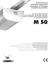
Product overview
This figure always offers you a complete overview of the ready-
assembled system during the step by step installation of the system.
Parts overview (Drivehead):
1. Drive head 1x
2. Remote control 2x
3. Support bracket 2x
4. Hardwarebag 1x
Parts overview (Rail):
5. Header bracket 1x
6. Door bracket 1x
7. Adapter for gear wheel 1x
8. Curved door arm 1x
9. Support bracket 2x
10. Hanging bracket 2x
11. Rail 1x
Hardwarebag:
1. Truss head screw
6 x 80 mm 1x
2. Lock nut M6 1x
3. Hexagonal head screw 4x
4. Nut M6 4x
5. Bolt 1x
6. Safety cotter pin 1x
7. Screw
ST6 x 50 mm 4x
8. Screw
ST6,3 x 18 mm 2x (4x)
9. Plug 4x
1. Header bracket
2. Belt
3. Rail
4. Carriage
5. Connecting piece
6. Mounting bracket
7. Support bracket
8. Power cable
9. Drive head
10. Release
11. Straight door arm
12. Curved door arm
13. Door bracket
2
3
Before you begin
IMPORTANT NOTE
If your garage does not have a side entrance, an external emergency
release should be installed. This allows for manual operation of the garage
door from the outside during power failure.
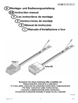
Door Types
A. One-Piece Door with Horizontal Track Only.
B. One-Piece Door with Horizontal and Vertical Track – Special door arm
(E, The Chamberlain Arm™) and the Protector System™
required. See your dealer.
C. Sectional Door with Curved Track – See 20B – connect door arm.
D. Canopy door – Special door arm (E, The Chamberlain Arm™) and the
Protector System™ required. See your dealer.
E. The Chamberlain Arm™ for use on door types B and D.
4
5
6
en 02/13
Preparation
First, check whether your door is balanced and in equilibrium.
Open your door about halfway and let it go.
The door can now hardly change its position independently,
but must remain in this position held by the spring force alone.
1. The rail of the garage door MUST be connected securely and firmly to
the supporting wall or ceiling above the garage door.
2. Additional brackets and mounting rails (not included in the supply) might
be required, if the your garage ceiling has a cladding, boards or similar.
3. If your garage does not have a separate side entrance, an external
emergency release (refer to section 34 “Optional Accessories”) must be
installed.
Tools required
6.1
7
Tool list:
Ladder
Marking pen
Pliers
Drilling machine
Hammer
Ratchet 10 mm / 13 mm
Hacksaw
Different drill bits for concrete
and(or wood
(8, 6, 5, 4.5 mm)
Box wrench
Water level
Screwdriver
Measuring tape

en 03/13
Assembly of the door opener
Important instructions for a safe installation.
Observe all assembly instructions.
Incorrect installation can cause serious injury.
Assembling the rail
The rail is largely preassembled and consists of 3 parts.
The carriage, push rod, release handle, the guide pulley and the lintel
bracket with belt tensioner are in the front part (A). The seating for the
drive shaft and the sprocket are in the rear part (B). Lay the front and
rear rail sections one behind the other.
Assembly of a 3-piece rail:
1. Remove cable ties that secure the belt.
2. Pull apart the two rail sections completely in order to create a gap for
the middle section (C). This rail is designed in such a way so as to
easily add the middle section. Slide the 2 connecting pieces (D) over the
seams of the rail sections up to the markings. To secure the connecting
pieces, bend the sheet metal lugs outwards with a suitable tool.
The assembly of the rail is complete.
Tighten the chain belt
Tighten the belt of the rail until the spring (1) is compressed only
by about half. The spring must compress and be able to bounce during
operation.
8
9
10
Fitting rail to the drive
1. Check if the belt is seated on the gear-wheel. If the belt has slipped off
during assembly, relax the belt, lay it and tighten again.
2. Turn around the rail (1) and completely put on the opener (3) with
the gear side (2).
3. Secure the rail on the opener with two mounting brackets (4) and
the screws (5).
Optional:
To reduce the total overall length by 140 mm the drive can be rotated by
90° as shown in fig.11. This allows access and programming sideways.
Unscrew the switch and mount it to the designated second position.
Remove the rubber plug in order to seal the cable exit.
Proceed with step 3.
This completes the assembly of the door opener.
11
Installation of the opener
Centre of the garage door
Eye protection goggles should be worn for overhead work.
All available barriers / locks should be deactivated to avoid damage
to the door.
To avoid serious injuries, remove all cables and chains connected to the
door before installing the door opener. The door opener should be mounted
at a height of at least 2.10 m above the ground.
First, mark the centre line of the door (1). Draw a line to the ceiling starting
from this point.
For installation on the ceiling, draw another line to the centre of the ceiling
(2) perpendicular to the door starting from this line.
Length approx. 2.80 m.
Mounting header bracket
Note:
Mount the rail max. 50mm above the top edge of the door.Depending on
the door type, the top edge of the door is lifted by a few cm during opening.
A. Wall fastening:
Mount header bracket (1) centrally on the vertical centre line (2); thereby its
lower edge lies on the horizontal line. Mark all holes for the header bracket.
Pre-drill holes with 4.5 mm diameter and fasten the
header bracket with wood screws (3).
Note:
In case of mounting on a concrete slab / concrete header, the provided
concrete plugs (4) and screws (3) should be used. Drill hole size in
concrete: 8 mm.
B. Ceiling suspension:
Draw vertical centre line (2) further up to the ceiling and about 200 mm
along the ceiling. Attach header bracket (1) centrally on the vertical
marking up to 150 mm removed from the wall. Mark all holes for the
header bracket. Drill holes with 4.5 mm diameter and fasten the header
bracket with wood screws (3).
12
12.1
13

en 04/13
Attaching drive to header
It may be necessary to place the drive temporarily higher, so
that the rail does not hit the springs in sectional doors.
The drive must either be well supported (ladder) or held firmly by
a second person. Put drive head on garage floor under the lintel bracket.
Lift rail up till the holes of the fixing part and the holes of the lintel bracket
are aligned. Insert screw (1) through the holes and secure with nut (2).
Hang opener
Fully open the door, put down door opener on the door (Fig. A).
Lay a piece of wood / cardboard on the marked spot (X).
The opener must be securely fastened to a structural support of the
garage.
Three representative installations are shown (Fig. B).
Yours may be different. Hanging brackets (1) should be angled to provide
rigid support. On finished ceilings, attach support bracket(not delivered) to
a self-supporting structio-nal element before installing the opener. For con-
crete ceiling mount, use concrete anchors (3) provided.
On each side of opener measure the distance from the opener to the
structural support (or ceiling).
Cut both pieces of the hanging bracket to required lengths. Flatten one
end of each bracket and bend or twist to fit the fastening angles.
Do not bend at the bracket holes. Drill 4,5mm pilot holes in the structural
supports (or ceiling). Attach brackets to supports with wood screws (4).
Lift opener and fasten to hanging brackets with screw and nut (5).
Check to make sure rail is centered over the door.
Remove piece of wood / cardboard. Operate door manually.
If door hits the rail, raise header bracket.
Pay attention to a horizontal course of the rail along the ceiling.
The distance can be adjusted by the given hole spacing.
Protruding ends of the ceiling fixture can be reduced if necessary.
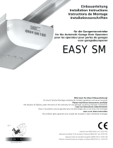
Mounting door bracket
Installation in sectional or one-piece doors:
The door bracket (1) has multiple mounting holes. Attach door bracket top
centre on the inside of the door as shown. Mark holes and screw door
bracket.
Mounting heights:
1. One-piece or sectional door with a guide rail:
distance to door top edge 0-100 mm.
2. Sectional door with two guide rails:
distance to door top edge 100-130 mm.
NOTE:
The attachment point on the door must be the frame or a stable place on
the door panel. If necessary, drill through and screw (not included) together
as shown in Fig. B.
14
15
16
Attaching door arm on the trolley
The straight door arm is already pre-assembled.
Pulling the red handle the trolley will be released and can be moved
manually.
DISCONNECT THE TROLLEY
1. The door should be fully closed if possible.
2. Pull down on the emergency release handle.
RECONNECT THE TROLLEY
The lockout feature prevents the trolley from reconnecting automatically.
Push the green button on the trolley. With the next door movement the
system will reconnect.
Mount the release handle of the emergency release at at height of
at least 1.80 m. Attach the yellow label regarding the release of
the garage door opener (sticker) on the cord of the door handle.
17
Electrical connection
In order to avoid personal injury and damage to the device, the
door opener should be operated only if such an instruction is
explicitly stated in this manual. The power plug must always be
accessible for the purpose of disconnecting the mains supply.
Install illuminated push button
Locate door control where the garage door is visible, away from door and
door hardware and out of the reach of children. Mount at least 1,5 m (5
feet) above the floor. Permanently fasten the caution label permanently to
the wall near the door control as a reminder of safe operating procedures.
There are 2 terminals on the back of the door control. Strip about 6mm of
insulation from bell wire. Separate wires enough to connect the white/red
wire to RED terminal screw and the white wire to WHT terminal screw.
Fasten the door control to an inside garage wall with sheet metal screws
(3) provided. Drill 4mm holes and use anchors (6) if installing into drywall.
A convenient place is beside the service door and out of reach of children.
Run the bell wire up the wall and across the ceiling to the garage door
opener. Use insulated staples (5) to secure wire.
Operation of the Door Control:
Press to open or close the door. Press again to stop the door while
moving.
19
18

en 05/13
Installation of photocells
(Optional accessory)
After installing and adjusting the door opener, photocells can be installed.
The installation instructions are included with the photocells.
The optional photocells ensure that the door is open, or remains
open, if people, especially young children, are in the door area.
By means of the photocells, a closing door is opened or an open door is
obstructed from closing, if a person located in the door area interrupts the
sensor beam.
Photocells are particularly recommended for families with young children.
20
Connecting the opener
Connect opener in accordance with local rules and regulations to a
properly installed wall socket.
NOTE:
When the opener is switched on, the operator light is also turned on
for 2.5 minutes.
Program opener and test
The door opener should only be used if the operator can see the
entire door area and is assured that it is free of obstacles
and the
door opener is set correctly. No one may pass through
the door while it is moving. Before the first opening operation, check that all
the facilities that are not needed are turned off. Remove all mounting aids
and tools from the pivot area of the door.
22
21
Setting the Limits
Travel limits regulate the points at which the door will stop when moving up
or down. Follow the steps below to set the limits.
This operator is equipped with a two speed system that is automatically set
by the software. Canopy or 1-piece garage doors will automatically run in
slow speed to insure a safe operation according regulatory. Doors traveling
shorter than 190 cm will run automatically slow.
INTRODUCTION
Your garage door opener is designed with electronic controls to make setup
and adjustments easy. The adjustments allow you to program where the
door will stop in the open (UP) and close (DOWN) position. The electronic
controls sense the amount of force required to open and close the door.
The force is adjusted automatically when you program the travel.
NOTE: If anything interferes with the door’s upward travel it will stop. If
anything interferes with the door’s downward travel, it will reverse.
To watch a short instructional video on programming your new garage door
opener use your smartphone to read the Code on this manuals back side
or visit www.chamberlain.eu.
PROGRAMMING BUTTONS
The programming buttons are located under a removable cover on the
back side of the garage door opener (see fig24).
23
1. Press and hold the square Adjustment Button until the UP Button begins
to flash.
2. Press and hold the UP Button until the door is in the desired UP position.
NOTE: The UP and DOWN Buttons can be used to move the door up
and down as needed.
3. Once the door is in the desired UP position press and release the
Adjustment Button. The garage door opener lights will flash and
the DOWN Button will begin to flash.
4. Press and hold the DOWN Button until the door is in the desired DOWN
position. Make sure the rail does not bend. NOTE: The UP and DOWN
Buttons can be used to move the door up and down as needed.
5. Once the door is in the desired DOWN position press and release the
Adjustment Button. The garage door opener lights will flash and the UP
Button will begin to flash.
6. Press and release the UP Button. When the door travels to the pro
grammed UP position, the DOWN Button will begin to flash.
Note: IF the door does not travel to the UP position the travel limit
programming failed. Begin again with step1.
If door travel is too short please refer to section 33 ”Frequently Asked
Questions”.
7. Press and release the DOWN Button. The door will travel to the
programmed DOWN position. Programming is complete.

Special Features
A. Door within a door connection
Description of feature:
Locate auxiliary quick connect terminals. Remove wire bridge.
Insert bell wire into quick connect terminals 4 and 5.
B. Flashing light connection
Description of feature:
The Chamberlain flashing light can be installed anywhere.
Connect light leads to quick connect terminals 6 and 7.
C. Partial opening feature
Description of feature: The pedestrian , ventilation or pet opening
position is an adjustable second stop position between the fully
opened and fully closed position of the garage door.
Activate:
NOTE: Any time programming requires pushing two buttons simul-
taneously, make sure this is executed accurately. If other buttons
than described will flash, briefly cut operator from current and start
programming from the beginning.
1. Move the door into to the desired partial opening position using
the remote control or wallcontrol.
2. Choose a non programmed button on your remote control.
3. Push square button and UP button simultaneously for 3 seconds
and wait for the operator light to flash. Then push the remote control
button. To program an additional remote control start again with
step1.
Deactivate:
1. Move the door to the fully closed position.
2. Push square button and UP button simultaneously for 3 seconds
and wait for the operator light to flash.
D. Instructions for Auto-Close Feature
Description of feature: The Chamberlain Safety IR Sensors must be
installed (required by EN60335-1-95).
Activate:
Push square and DOWN button simultaneously until th eoperator light
blinks. 1 push UP button = 10 seconds. up to 180 sec. possible (18x)
During countdown the down button flashes.
To complete programming push square button.
Deactivate:
Push square and DOWN button simultaneously until th eoperator light
blinks.
To complete programming push square button.
Notes:
- The auto-close timer resets if the IR sensors are interrupted.
- In the partial open position automatic close is not possible.
- The garage door operator must have reached the programmed UP
limit to activate the auto-close timer.
en 06/13
Test the Safety Reverse System
The safety reverse system test is important. Garage door
must reverse on contact with a 50 mm obstacle laid flat
on the floor. Failure to properly adjust opener may result
in serious personal injury from a closing garage door. Repeat test
once a month and adjust as needed.
OBSTACLE TEST:
Place a 50 mm high obstacle (1) under the garage door on the floor.
Move door downwards. The door must reverse when it comes into contact
with the obstacle. If upon contact the door stops, the door does not move
down far enough. In this case repeat limit setting .
If the door reverses after contact with the 50 mm high obstacle, remove
obstacles and open and close the door completely once. The door should
not go back, if it reaches the door position „Closed“. If it still reverses both
limits must be reprogrammed.
OPENING TEST: Apply 20 kg to the middle of the door.
The door should not open completely.
Program your opener and remote / the
Wireless push button (optional)
Activate the opener only when door is in full view, free of obstruction
and properly adjusted. No one should enter or leave garage while door
is in motion. Do not allow children to operate push button(s) or
remote(s). Do not allow children to play near the door.
Your garage door opener receiver and one of the buttons remote control are
pre-programmmed. If you purchase additional remote controls, the garage
door opener must be programmed to accept the new remote code.
Program the Receiver to Match Additional Remote Controls:
Using the yellow round button
1. Press and release the yellow round button on the opener. The learn
indicator light will glow steadily for 30 seconds (1).
2. Within 30 seconds, press and hold the button on the hand-held remote that
you wish to operate your garage door (2).
3. Release the button when the opener light blinks once. It has learned the
code. If the light bulb is not installed.
Now the opener will operate when the remote control push button is
pressed. If you release the remote control push button before the opener
light flashes, the opener has not learned the code.
To Erase all Remote Control Codes
To deactivate any unwanted remote, first erase all codes: Press and hold
the yellow round button on opener until the learn indicator light goes out
(approximately 10 seconds). All previous codes are now erased.
Reprogram each remote or keyless entry you wish to use.
26
24
25

en 07/13
Troubleshooting:
Question: Operator will not work anymore without IR sensor.
Solution: Correct. IR sensors are mandatory once connected.
A full logic board reset is required.
E. OPEN, STOP or CLOSE programming of the remote control.
Description of feature:
Each remote control button can be programmed to either OPEN,
STOP or CLOSE the door.
OPEN:
Push yellow round button and UP button simultaneously until the led
goes on. Now push a selcted button on the remote control for OPEN
only and wait for the operator light to flash.
STOP:
Push yellow round button and square button simultaneously until the
led goes on. Now push another selcted button on the remote control
for STOP only and wait for the operator light to flash.
CLOSE:
Push yellow round button and DOWN button simultaneously until the
led goes on. now push a third button on the remote control for
CLOSE only and wait for the operator light to flash.
F. Keyless entry (requires 747REV wireless keypad):
Enter a 4 digit code of your choice to operate the door.
G. Temporary access (requires 747REV wireless keypad):
A temoprary code can be programmed to allow limited acces to the
garage (by time or number of openings).
L. One button close feature (requires 747REV wireless keypad):
Without having the access code the door can be closed from any
position (not opened).
N. myQ (requires 830REV gateway):
Allows operating your garage door opener via internet or a compatible
mobile phone.
O. Garage Door Monitoring (requires 829REV Garage Door Monitor):
Features optical (by LEDs) and audible control of the status of your
garage door. Allows closing your garage door from the place this
device is installed.
P. Laser Park Garage Sensor
(photocells and laser park sensor required)
Quick connection terminals 2 and 3
(available from around July 2013)

Operation of the door opener
Automatic opening / closing of the door:
The door opener can be operated using the following devices:
• Remote control: Press the button until the door starts to move.
• Wall switch (if this accessory is installed): Press the pushbutton until
the door starts to move.
Manual opening of the door (by hand):
If possible, the door must be closed completely. Weak or defective
springs can cause a rapid shutting down of the open door, which
can lead to property damage or serious personal injury.
RELEASE: Briefly pull the red handle down. Then open the door by hand.
Open close door without pulling the cable!
RECONNECT:
The lockout feature prevents the trolley from reconnecting automatically.
Push the green button on the trolley. With the next door movement the
system will reconnect.
Function sequence:
When operating the door opener by radio control or wall switch:
- closes the door when it is fully open,
- opens the door when it is fully closed,
- stops the door if it is opening or closing,
- the door moves in the opposite direction to the last completed move,
if it is partially open,
- drives back the door to the open door position, if it hits an obstruction
while closing,
- stops the door, if it encounters an obstacle during opening.
- Photocells (optional): By means of the photocells, a closing door
is lifted up or an open door is obstructed while closing, if a person
located in the door area interrupts the beam.
- THE MULTI-FUNCTION DOOR CONTROL (optional)
Press the push bar (1) to open or close the door. Press again to stop
the door.
Light feature
Press the Light button (2) to turn the opener light on or off. It will not
control the opener light when the door is in motion. If you turn it on and
then activate the opener, the light will remain on for 2-1/2 minutes.
Press again to turn it off sooner.
The operator light switches on in the following cases:
1. First turning on of the door opener (short)
2. Power interruption (short)
3. With each turning on of the door opener.
The light turns off automatically after 2 1/2 minutes.
Attach warning labels
(see fig. 28)
en 08/13
Cleaning and maintenance
Before any maintenance, cleaning and related maintenance
work, the mains supply plug should be pulled out. Danger
from electric shock!
Maintenance of the door opener
A proper installation ensures the optimum performance of the door opener
with minimum maintenance. An additional lubrication is not required. Gross
dirt accumulation in the guide rail may impair the function and must be
removed.
Cleaning
Clean the drive head, wall switch and remote control with a soft, dry cloth.
Do not use liquids.
Maintenance
Check the system often, especially cables, springs and fasteners,
for signs of wear, damage or lack of balance. Do not use if repair
or adjustment work must be performed, because an error in the
system or an incorrectly balanced door may cause injury.
Once a month:
• Check automatic safety reverse again and reset if necessary.
• Operate door manually. If the door is unbalanced or stuck, please
contact the service centre.
• Check for complete opening and closing of the door.
Where appropriate, readjust limit switches and / or power.
Twice a year:
• Check the chain belt tension. For this, first disconnect the carriage
from the drive. If necessary, adjust belt tension.
• Lightly lubricate the guide rail with standard grease (lubrication).
Once a year (at the door):
• Lubricate door roller, bearings and joints. An additional lubrication of
the door opener is not required.
Do not grease the door rails!
Limit switch adjustment and force regulation:
These settings must be checked and undertaken properly during the
installation of the opener. Due to weathering, minor changes can occur
during operation of the opener that need to be addressed by a new setting.
This can particularly happen in the first year of operation.
Follow the instructions for setting travel limits and force (refer to section 23
and 33) carefully and re-check the automatic safety reverse after each
resetting.
30
30.1
28
29
27

Replace batteries of the remote control
Battery of the remote control:
The batteries in the remote have an extremely long life.
If the transmission range decreases, the batteries must be replaced.
Batteries are not covered by the guarantee.
Please observe the following instructions for battery:
Batteries should not be treated as household waste.
All consumers are required by law to dispose of batteries properly at the
designated collection points.
Never recharge batteries that are not meant to be recharged.
Danger of explosion!
Keep batteries away from children, do not short-circuit them or take them
apart.
See a doctor immediately, if a battery is swallowed.
If necessary, clean contacts on battery and devices before loading.
Remove exhausted batteries from the device immediately!
Increased risk of leakage!
Never expose batteries to excessive heat such as sunshine, fire or the like!
There is increased risk of leakage!
Avoid contact with skin, eyes and mucous membranes. Rinse the parts
affected by battery acid with plenty of cold water and consult a doctor
immediately.
Use only batteries of the same type.
Remove the batteries if the device is not being used for a long time.
Replacing battery:
To replace battery, turn remote control around and open the case with a
screwdriver. Lift cover and lift control board below. Slide battery to one side
and remove. Watch polarity of battery!
Assemble again from in reverse direction.
ATTENTION!
Danger of explosion if battery is replaced improperly.
Replacement only by identical or equivalent type (10A20-WH).
Operator light
The LED lighting has a very long life and is maintenance free.
The lens cover cannot be removed.
31
Disposal
The packaging is made from environmentally friendly materials. It can
be disposed of in the local recycling bin. According to the European
Directive 2002/96/EC on waste electrical and electronic equipment, this
device must be properly disposed of after use to ensure the reuse of
materials. The information on the possibilities of this waste disposal is
provided by the local government or municipality.
32
en 09/13
Frequently asked questions
1. Door opener doesn’t work with remote control:
• Is the opener connected to the power supply? If a lamp connected
to the power socket does not turn on, check fuse or circuit breaker.
(Some sockets are enabled via a wall switch).
• Are all door locks disabled?
See safety instructions!
• Check if remote control battry is lit.
• Try operating with a new battery.
• If you have two or more remote controls, of which only one works,
check programming of the receiver.
• Is there snow / ice under the door? If yes, the door may be frozen
onto the ground. Remove all obstacles.
• Perhaps the door spring is defective. This must be replaced by
a specialist.
2. Transmission range of the device is too low:
• Is a battery inserted? Put in a new battery.
• Try radio control in the car at another location.
• The transmission range diminishes for metal doors, aluminium or metal
panels.
3. Door reverses for no apparent reason:
• Is the door blocked by anything? Pull manual release and operate door
by hand. In case of unbalanced or stuck gate, please contact the service
department.
• Re-program operating force.
• Clear ice or snow in the closing area of the door.
• If the door reverses upon reaching the door position ‘Closed’,
the limit switch must be set for this door position.
After completing every setting, the automatic safety reverse must
be checked again:
• An occasional resetting of the end positions is not unusual.
In particular, the weathering can shift the doorway.
4. The garage door opens and closes by itself:
• Delete all remote controls and then re-programme them.
See section 25.
• Is the remote control button jammed in position „ON“?
• Use only original remote controls! The use of third-party products leads
to disturbances.
• The remote control button was pressed accidentally (pocket).
• Cable of the wall switch is damaged (remove for testing purposes).
• An accessory connected to the opener causes the drive (remove
for testing purposes).
5. Door does not close completely:
• Re-programme stretch of way of the opener. Check for alterations
in the mechanical components, e.g. door arms and fittings.
After each new setting of the door position ‘Closed’,
the automatic safety reverse should be checked for function.
33
30.2

en 10/13
6. The door opens, but does not close:
• If installed, the photocells should be checked. If the LED at the photocells
blink, the alignment should be checked.
• Check remote control or wall switch for function.
7. Operator light doesn’t turn on:
• Open or close door. The light remains switched on for 2.5 minutes.
• Disconnect opener from the mains and connect again.
The light comes on for a few seconds.
• No power.
8. Operator light doesn’t turn off:
• Disconnect the power from the mains supply for a short time and try
again.
• The 2.5 minutes are not yet over.
9. Motor hums and runs very briefly, but does not function:
• Garage door springs are defective. Close the door and disconnect
from the opener by pulling on the handle of the carriage (manual
release). Open and close door manually. If the door is properly
balanced, it is held at each point of the doorway by the door springs
alone. If this is not the case, contact your service centre.
• If this problem appears during the first use, the door may be locked.
Deactivate door lock.
• Release opener from the door and try without door. If the door is fine,
reprogramme operating force and stretch of way.
10. Opener works only in one direction:
• Door springs may be defective or the door is stiff in one direction.
• If the door is fine, re-programme operating power and stretch of way
of the opener.
11. The belt rattles on the rail:
• Adjust the belt tension. The cause is usually a very tight chain/belt.
The spring on the clamping device of the rail must not be
compressed completely.
• The door runs unevenly and makes the drive vibrate. Improve door run.
12. Opener will not start due to power failure:
• Disconnect from the opener by pulling on the handle on the carriage
(manual release). The door can now be manually opened and closed.
If the opener is re-activated, the carriage also gets re-connected.
• If installed, the carriage is detached from the drive in case of power
failure by an external emergency release from outside the garage.
13. Door reverses after the force was programmed:
• See if the rail bends. The opener requires a lot of power to move the
door. Repair or install door correctly.
• Door is very heavy or in poor condition. Call a specialist.
14. Rail bends on the opener:
• Door is heavy, very heavy, stiff or in poor condition. Call a specialist.
• A swing of the rail while moving is a sign of an unevenly functioning door
with constantly changing power requirements. Call specialist, possibly
lubricate door. An additional suspension on the rail can be a remedy.
15. The opener „runs“ (audible turning of motor) but the carriage does
not move:
• The carriage is released from the opener.
• In a new installation: During the assembly of motor and rail, the
pre-assembled adapter sleeve between the motor shaft and the rail
was not installed. This sleeve is pre-assembled at factory, but can
be removed. Standing behind the opener it can be observed whether
the gearwheel turns in the rail or just the motor.
• In a new installation: The belt has come off from the gearwheel in the rail.
Standing behind the opener, you can see the gearwheel.
• After years of use: Is the release defective or continuously disengaged?
• After years of use: The sleeve between rail and motor or the motor
control gear is defective.
16. The door releases by itself from the carriage and stops:
• An external release that has been installed during a power failure
should be checked whether it stretches and releases during the
opening of the door. Watch the mechanism and reset if necessary.
• The handle of the release mechanism should not get caught in other
items.
17. Setting the Force
The force setting button is located behind the cover at the operators
backside. The force setting regulates the amount of power required
to open and close the door.
1. Open cover on the backside of the opener.
Locate the yellow round button (2).
2. Push the yellow round button (2) twice to enter unit into Force
Adjustment Mode. The LED (3) (indicator light) and the UP button will
flash. Push UP button. The operator will travel to the UP position
learning the required amount of force. Once the UP limit is reached the
LED and the DOWN button a start to flash. Push DOWN button.
The operator will travel to the DOWN position learning the required
amount of force.

en 11/13
Diagnostic Chart
Your garage door opener is programmed with self-diagnostic capabilities. The UP and DOWN arrows on the garage opener flash the diagnostic codes.
DIAGNOSTIC CODE
Up Arrow Down Arrow
Flash(es) Flash(es)
11
12
13
14
15
16
2 1-5
32
4 1-4
45
46
SYMPTOM
The garage door opener will not
close and the light bulbs flash
The garage door opener will not
close and the light bulbs flash.
The door control will not function.
The garage door opener will not
close and the light
Door moves 6-8" stops or reverses.
No movement, only a single click.
Opener hums for 1-2 seconds no
movement.
Door coast after it has come to a
complete stop.
No movement or sound.
Unable to set the travel or retain
position.
Door is moving stops and or
reverses.
Opener runs approximately 6-8",
stops and reverses.
The garage door opener will not
close and the light bulbs flash.
SOLUTION
Safety sensors are not installed, connected or wires may be cut. Inspect sensor wires-
for a disconnected or cut wire.
There is a short or reversed wire for the safety sensors. Inspect safety sensor wire at
all staple points and connection points and replace wire or correct as needed.
The wires for the door control are shorted or the door control is faulty. Inspect safety
sensor wire at all staple points and connection points and replace wire or correct as
needed.
Safety sensors are misaligned or were momentarily obstructed. Realign both sensors
to ensure both LEDs are steady and not flickering. Make sure nothing is hanging or
mounted on the door that would interrupt the sensors path while closing.
Manually open and close the door. Check for binding or obstructions, such as a broken
spring or door lock, correct as needed. Check wiring connections at travel module and
at the logic board. Replace travel module if necessary.
Manually open and close the door. Check for binding or obstructions, such as a broken
spring or door lock, correct as needed. Replace logic board if necessary.
Manually open and close the door. Check for binding or obstructions, such as a broken
spring or door lock, correct as needed. Replace motor if necessary.
Program travel to coasting position or have door balanced by a trained technician.
Replace logic board.
Please refer to section 33 “Frequently Asked Questions”, chapter 15
Manually open and close the door. Check for binding or obstructions, such as a broken
spring or door lock, correct as needed. If the door is binding or sticking contact a
trained door systems technician. If door is not binding or sticking attempt to reprogram
travel (refer to page 24 ).
Please refer to section 33 “Frequently Asked Questions”, chapter 15
Safety sensors are misaligned or were momentarily obstructed. Realign both sensors
to ensure both LEDs are steady and not flickering. Make sure nothing is hanging or
mounted on the door that would interrupt the sensor's path while closing.

en 12/13
DIAGNOSTIC CODE
Up Arrow Down Arrow
Flash(es) Flash(es)
51
55
61
SYMPTOM
Terminal 1+2 for wall control is short-
ened longer than 4 seconds
Low voltage
Maximum radio memory has been
reached.
SOLUTION
Check wiring for push button if button is stuck and activated permanently. Remove
wiring from terminal 1+2 on operator as test. Do not run push button wires next to high
voltage wiring or in same conduit.
The operator has been shut off due to lower voltage supplied than allowed.
If an external backup battery pack is installed, check if empty. If mains supply is used,
check wiring and supply.
Maximum capacity for storage of remote controls has been reached. The first remote
control or more previously programmed remote controls’ codes have been replaced by
a new one. To reset diagnostic remove power from the operator.
Optional Accessories
1. TX4RUNI - 4-channel remote control
2. 128REV - Wireless Wall Control 2-Channel
3. 747REV - Keypad
4. 830REV - myQ Starter Kit (Gateway + Photocells)
5. 829REV - Garage Door Monitor
6. 1REV - Quick release
7. 1702REV - Quick release
8. 75REV - Wired push button
9. FLA-1LED - Flashing light
10. 771REV - Photocells
11. 41REV - Key switch (surface mount)
12. 16200LM - Door in Door contact
34

en 13/13
Service parts / Warranty
Please refer to www.chamberlain.eu or contact your local dealer.
Also refer to the available Warranty Book.
36
37
B. P. Kelkhoff
Manager, Regulatory Affairs
Chamberlain GmbH
Alred-Nobel-Str. 4
D-66793 Saarwellingen
February 2013
Declaration of conformity
The listed automatic garage door opener corresponds to the
applicable sections of the standards EN 55014-1 (2006), EN
55014-2 (2008), EN 61000-4-2 (2009), EN 61000-4-3 (2008),
EN 61000-4-4 (2004), EN 61000-4-5 (2007), EN 61000-4-6
(2009), EN 61000-4-11 (2004), EN 62233 (2008), EN 300220-
1 (V2.3.1),
EN 300220-2 (V2.1.2), EN 60335-1 (2010), EN 60335-2-95
(2004) in accordance with the provisions and all amendments
to the European Directives 2004/108/EC, 2006/95/EC,
2006/42/EC and 1999/5/EG.
Model: ...................................................ML700EV, ML1000EV
S./N.: ............................................xxxxx000001 - xxxxx99999
Manufacturer ........................................Chamberlain GmbH
...........................................Alfred-Nobel-Str. 4
...................................D-66793 Saarwellingen
All technical archive data for the opener and the associated
accessories are kept safe by Chamberlain GmbH and will be
provided to the authorities on request if required.
Declaration of conformity
Specifications
Input Voltage...................230-240 VAC, 50 Hz
Max. Pull Force ..............700 N (COMFORT), 1000 N (PREMIUM)
Standby Power
(door fully closed)...........0.8 W
Motor
Type................................DC gearmotor permanent lubrication
Noise level......................54dB
Drive Mechanism............Belt
Length of Travel..............Adjustable
Opening speed, up to ....160 mm/s (COMFORT), 200 mm/s (PREMIUM)
Lamp...............................On when door starts, off 2-1/2 minutes
after stop.
Door Linkage ..................Adjustable door arm. Pull cord trolley release.
Safety
Personal .........................Push button and automatic stop in down
direction. Push button and automatic stop in
up direction.
Electronic........................Automatic force adjustment
Electrical .........................Transformer overload protector and low
voltage push button wiring.
Limit Device ....................Mechanical RPM/Passpoint detector.
Limit Adjustment .............Electronic
Soft-Start / Soft-Stop........all
Dimensions
Length (Overall)...............3200 mm
Headroom Required .......30 mm
Hanging Weight ..............~12 kg
Receiver
Memory Registers ..........180
Operating Frequency.......6-Band (433 MHz / 868 MHz)
SPECIAL NOTE: Chamberlain strongly recommends installing photocells
on all garage door openers.
35

114A4C035B 2013, all rights reserved
Chamberlain GmbH
Alfred-Nobel-Strasse 4
66793 Saarwellingen
Germany
www.chamberlain.eu

114A4C036
30.2
34
25
24
23
17
1
▲
▐
▲
▐
▲
▐
▲
▐
1
12VDC
Pb Cd Hg
27
19 - 20
0 1 2 2 3 4 5 6 7
0 1 2 2 3 4 5 6 7
24 VDC
+ -
24 VDC
+ -
1+2
2+3
2
3
4
5
6
7
service:
www.chamberlain.de
B
B
B
A
A
B
A
A
B
en
ACHTUNG - Einklemmgefahr
Regelmässig überprüfen und wenn notwendig einstellen, um
sicher zu sein, dass das Tor umkehrt, wenn es einen 50 mm
hohen Gegenstand berührt, der auf den Boden gestellt wurde.
de
CAUTION - Danger of Entrapment
Regularly check and adjust if necessary to ensure that the
door reverses when it touches a 50 mm high object that
is placed on the floor.
fr
ATTENTION - Risque d’écrasement
Vérifier régulièrement, et eégler si nécessaire, pour s’assurer
que la porte inverse son mouvement lorsqu’elle rencontre un
objet de 50 mm de haut placé sur le sol.
pt
ATENÇÃO - Perigo de entalamento
Verificar regularmente e se necessário, ajustar para se
assegurar de que o portão volta para trás ao tocar num
objecto com uma altura de 50 mm que foi clocado no chão.
nl
LET OP - Inklemmingsgevaar
Regelmatig controleren en indien nodig instellen om zeker
te zijn dat de poort terugdraait als deze een 50 mm hoog
object aanraakt dat op de grond werd geplaatst.
es
ATENCIÓN - Peligro de aprisionamiento
Comprobar regularmente y ajustar cuando sea necessario
para garatizar que la puerta se invierta cuando toca un
objeto de 50 mm de altura que se colocó en el suelo.
da
ADVARSEL - fare for indklemming
Porten skal kontrolleres og om nøvendigt justeres for at
sikre, at den går tilbage, når den berører en 50 mm høj
genstand, der er blevet stillet på jorden.
it
ATTENZIONE - Pericolo di incastro
Verificare sistematicamente e, se necessario, regolare in
maniera adeguata onde assicurare che la porta torni indietro
se viene in contatto con un oggetto alto 50mm posto a terra.
no
FORSIKTIG - Klemmefare
Etter at døren har berørt en gjenstand som har stått 50mm over
gulvhøyde, må du jevnlig sjekke om døren går feilfritt.
Juster om nødvendig.
HUOMIO - puristumisvaara
Tarkista säännöllisesti ja milloin tarpeellista säädä, ollaksesi
varma, että portti kääntyy takaisin, kun se koskettaa 50 mm
korkeaa kohdetta, joka on asetettu maan pinnalle.
fi
el
sv
VARNING - klämningsrisk
Kontrollera regelbundet och justera om det behövs, för att vara
säker på att porten vänder när den träffar ett 50 mm högt
föremål, som placerats på golvet.
hr
cz
tr
ro
sk
sr
ro
sk
sr
hu
sl
bg
pl
cn
rus
114A4354
service:
www.chamberlain.de
B
B
B
A
A
B
A
A
B
en
ACHTUNG - Einklemmgefahr
Regelmässig überprüfen und wenn notwendig einstellen, um
sicher zu sein, dass das Tor umkehrt, wenn es einen 50 mm
hohen Gegenstand berührt, der auf den Boden gestellt wurde.
de
CAUTION - Danger of Entrapment
Regularly check and adjust if necessary to ensure that the
door reverses when it touches a 50 mm high object that
is placed on the floor.
fr
ATTENTION - Risque d’écrasement
Vérifier régulièrement, et eégler si nécessaire, pour s’assurer
que la porte inverse son mouvement lorsqu’elle rencontre un
objet de 50 mm de haut placé sur le sol.
28
1: 0-100 mm
2: 100-130 mm
4x
1
B
A
16
1
2
34
5
6
78
910 11 12
/