Page is loading ...

ECR International Inc
2201 Dwyer Avenue
Utica, NY 13501
e-mail: info@RetroAire.com
e Right Fit for Comfort
P/N 240008206, Rev. F [02/15/2013]
An ISO 9001-2008 Certifi ed Company
™
R11C R12C R21C
R22C
/
H R23C
/
H R24C
/
H
Packaged Terminal Air Conditioner (PTAC)
Installation, Operation
& Maintenance Manual
R11C
Replacement for:
Westinghouse "RB" Series Chassis
R12C
Replacement for:
Lennox PTEIA Series
R21C
Replacement for:
Climate Master (Friedrich) 701 Series
R22C | R22H
Replacement for:
ICE Cap RSK & IslandAir EZ-RK Series
R23C | R23H
Replacement for:
IceCap Custom RSK Units
R24C | R24H
Replacement for:

TABLE OF CONTENTS
Information and specifi cations outlined in this manual in effect at the
time of printing of this manual. ECR International reserves the right to
discontinue, change specifi cations or system design at any time without
notice and without incurring any obligation, whatsoever.
NOTICE
RetroAire™ replacement PTAC/PTHP is backed by
EMI and ECR International and is tested and rated in
accordance with: AHRI Standards 310/380 UL-484
Receiving Information .....................................................................................................3
Important Safety Information ...........................................................................................4
Dimensional/Physical Data ...............................................................................................5
Product Description ....................................................................................................... 11
Ptac/Pthp Installation Preparation ................................................................................... 15
Installation Instructions — R11C ..................................................................................... 16
Installation Instructions — R12C ..................................................................................... 18
Installation Instructions — R21C ..................................................................................... 20
Installation Instructions — R22C | R22H .......................................................................... 22
Installation Instructions — R23C | R23H .......................................................................... 24
Installation Instructions — R24C | R24H .......................................................................... 26
Sequence Of Operation.................................................................................................. 28
Inspection & Start-Up ................................................................................................... 31
Maintenance ................................................................................................................ 37
Troubleshooting ............................................................................................................ 39
Electrical Specifi cations ................................................................................................. 40
Operational Performance Data ........................................................................................ 43
Model Number ............................................................................................................. 45
The Right Fit for Comfort 2 P/N 240008206, Rev. F [02/15/2013]

RECEIVING INFORMATION
Shipping damage MUST be reported to the carrier IMMEDIATELY.
Examine exterior.
Remove cover and examine compressor and piping for signs of damage.
Inspection
Check shipment against bill of lading.
Verify equipment received as ordered.
Verify unit:
• Unit size and type correct per submittal sheet and
job requirements?
• Voltage correct?
• Hydronic coil included, if required? Piping located
as required?
• Factory installed options installed?
• All fi eld installed options included?
Inspect each component for damage. Concealed damage
must be reported to carrier within 15 days of receipt of
shipment.
• Carrier must make proper notation on delivery receipt
of all damage identifi ed and complete carrier inspection
report.
Purchaser must notify Manufacturer’s Service department
of all damage and is responsible for fi ling any necessary
claims with carrier.
Customer Service : (800) 228-9364
General Information
Installation shall be completed by qualifi ed agency.
Retain
this manual and warranty for future reference.
Installer review this manual to verify unit has been
installed correctly. Run unit for one complete cycle to
verify proper function.
To obtain technical service or warranty assistance
during or after installation, contact your local
representative.
Visit our web site www.retroaire.com for local
representative listing.
For further assistance call 1-800-325-5479.
When calling for assistance, please have following
information ready:
Model Number_________________________
Serial Number_________________________
Date of installation______________________
P/N 240008206, Rev. F [02/15/2013] 3 Made in USA

IMPORTANT SAFETY INFORMATION
Become Familiar With Symbols
Become Familiar With Symbols
Identifying Potential Hazards.
Identifying Potential Hazards.
All fi eld wiring shall conform to requirements of authority
having jurisdiction or in absence of such requirements:
• United States - National Electrical Code, ANSI/NFPA
70
• Canada - CSA C22.1 Canadian Electrical Code Part 1.
Safety Information
• Installation by qualifi ed personnel.
• Turn off electrical supply before servicing unit.
• Inspect all parts for damage prior to installation and
start-up.
• Do not use unit if it has damaged wiring, is n
ot
ot
workin
working properly, or has been damaged or dropped.
• Connect to properly grounded electrical supply with
proper voltage as stated on rating plate.
• Have proper overcurrent protection (i.e. time- delay
fuse/HACR Breaker) as listed on Rating Plate.
• Connect unit to properly grounded electrical supply.
Do not fail to properly ground this unit.
• Tampering voids all warranties.
DANGER
Indicates a hazardous situation which, if not
avoided, WILL result in death or serious injury.
!
WARNING
Indicates a hazardous situation which, if not
avoided, could result in death or serious injury.
!
CAUTION
Indicates a hazardous situation which, if not
avoided, could result in minor or moderate injury.
!
!
NOTICE
Indicates information which should be followed to
ensure proper installation and operation.
WARNING
Fire, explosion, and electrical shock hazard.
Improper installation could result in death or
serious injury. Read this manual and understand all
requirements before beginning installation.
!
WARNING
Tampering with PTAC/PTHP is dangerous and could
result in serious injury or death. Do not modify or
change this unit.
!
The Right Fit for Comfort 4 P/N 240008206, Rev. F [02/15/2013]

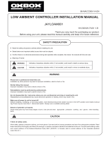
Figure 1 R11C Dimensions - Inches (mm)
Table 1 Nominal Capacities, Dimensions, Shipping Weights
Dimension
Model
R11C
in. (mm)
A 21
.81
(554)
B 34.44 (875)
C 13.96 (355)
D 18.63 (473)
E 26.00 (660)
F 18.62 (473)
G 4.00 (102)
H 3.60 (91)
Table 2 R11 | R21 Performance Data
Model
R11 | R21
Cooling
Sensible
Heat
Ratio
EER
Indoor Air
Flow
Fresh Air
Inlet Flow
Outdoor
Sound
Level
Shipping
Weight
Btuh (kW)
CFM (L/s)CFM (L/s) dBa lbs (Kg)
R_ _C 09 9,200 (2.7) 0.79 9.5 400 (189) 35 (17) 75 140 (64)
R_ _C 12 12,000 (3.5) 0.66 8.8 400 (189) 50 (24) 69 140 (64)
R_ _C 15 14,700 (4.3) 0.69 8.3 425 (200) 60 (28) 70 140 (64)
R_ _C 18
16,500
(4.8)
0.67 8.3
425
(200)
95 (45) 69
140
(64)
Straight cooling nominal capacities
9,000 12,000 15,000 18,000 Btuh
2.6 3.5 4.4 5.3 kW
DIMENSIONAL/PHYSICAL DATA
P/N 240008206, Rev. F [02/15/2013] 5 Made in USA

Figure 2 R12C Chassis
Table 3 R12 Performance Data
Model
R12
Cooling
Sensible
Heat
Ratio
EER
Indoor Air
Flow
Fresh Air
Inlet Flow
Outdoor
Sound
Level
Shipping
Weight
Btuh (kW) CFM (L/s) CFM (L/s) dBa lbs (Kg)
R_ _C 12 13,200 (3.9) 0.67 9.6 400 (189) 50 (24) 69 140 (64)
R_ _C 15 16,000 (4.7) 0.64 9.0 425 (200) 60 (28) 70 140 (64)
DIMENSIONAL/PHYSICAL DATA
Table 4 Nominal Capacities, Dimensions, Shipping Weights
Dimension
Model
R12C
in. (mm)
A 22.03 (559)
B 36.25 (921)
C 21.88 (556)
D 25.48 (647)
E 21.03 (534)
F 4.10 (104)
G 9.62 (244)
Weather
Angle
4.66 (118)
Straight Cooling Nominal Capacities
12,000 15,000 Btuh
3.5 4.4 kW
The Right Fit for Comfort 6 P/N 240008206, Rev. F [02/15/2013]

Table 5 R11 | R21 Performance Data
Model
R11 | R21
Cooling
Sensible
Heat
Ratio
EER
Indoor Air
Flow
Fresh Air
Inlet Flow
Outdoor
Sound Level
Shipping
Weight
Btuh (kW) CFM (L/s) CFM (L/s) dBa lbs (Kg)
R_ _C 09 9,200 (2.7) 0.79 9.5 400 (189) 35 (17) 75 140 (64)
R_ _C 12 12,000 (3.5) 0.66 8.8 400 (189) 50 (24) 69 140 (64)
R_ _C 15 14,700 (4.3) 0.69 8.3 425 (200) 60 (28) 70 140 (64)
R_ _C 18 16,500 (4.8) 0.67 8.3 425 (200) 95 (45) 69
140
(64)
Figure 3 R21C Chassis
DIMENSIONAL/PHYSICAL DATA
Table 6 Nominal Capacities, Dimensions, Shipping Weights
Dimension
Model Model
R21C -09
in. (mm)
R21C -18
in. (mm)
A 35.88 (911.2) 35.88 (911.2)
B 14.78 (375.5) 14.78 (375.5)
C 7.75 (196.9) 14.40 (365.7)
D 20.25 (514) 24.34 (618.2)
E 18.98 (482.1) -
F 28.28 (718.3) -
G 5.66 (143.8) 5.66 (143.8)
Straight Cooling Nominal Capacities
9,000 12,000 15,000 18,000 Btuh
2.6 3.5 4.4 5.3 kW
P/N 240008206, Rev. F [02/15/2013] 7 Made in USA

Table 7 R22 | R23 | R24 H Performance Data
Model
R22_ | R23_ | R24_
Cooling
Sensible
Heat
Ratio
EER
Heat Pump
COP
Indoor Air
Flow
Fresh Air
Inlet Flow
Outdoor
Sound
Level
Shipping
Weight
Btuh (kW) Btuh (kW) CFM (L/s) CFM (L/s) dBa lbs (Kg)
R_ _C 09 9,200 (2.7) 0.79 9.5 N/A N/A 400 (189)
35 (17) 75 140 (64)
R_ _H 09 9,200 (2.7) 0.79 9.5 8,500 (2.5) 2.90 400 (189)
R_ _C 12 12,000 (3.5) 0.66 8.8 N/A N/A 400 (189)
50 (24) 69 140 (64)
R_ _H 12 12,000 (3.5) 0.66 8.8 11,700 (3.4) 2.60 400 (189)
R_ _C 15 14,700 (4.3) 0.69 8.3 N/A N/A 425 (200)
60 (28) 70 140 (64)
R_ _H 15 14,700 (4.3) 0.69 8.3 14,000 (4.1) 2.52 425 (200)
R_ _C 18 16,500 (4.8) 0.67 8.3 N/A N/A 425 (200) 95 (45) 69 140 (64)
Heat Pump Nominal Capacities
9,000 12,000 15,000 Btuh
2.6 3.5 4.4 kW
Table 8 Nominal Capacities, Dimensions, Shipping Weights
Dimension
Model
R22C/R22H
in. (mm)
A 35.89 (912)
B 14.98 (380)
C .94 (24)
D 8.98 (228)
E 19.09 (485)
F 5.00 (127)
G 17 (432)
H 38.04 (966)
I 25.13 (638)
J .96 (24)
Figure 4 R22C/R22H Chassis
DIMENSIONAL/PHYSICAL DATA
Straight cooling nominal capacities
9,000 12,000 15,000 18,000 Btuh
2.6 3.5 4.4 5.3 kW
The Right Fit for Comfort 8 P/N 240008206, Rev. F [02/15/2013]

Table 9 R22 | R23 | R24 H Performance Data
Model
R22_ | R23_ | R24_
Cooling
Sensible
Heat
Ratio
EER
Heat Pump
COP
Indoor Air
Flow
Fresh Air
Inlet Flow
Outdoor
Sound
Level
Shipping
Weight
Btuh (kW) Btuh (kW) CFM (L/s) CFM (L/s) dBa lbs (Kg)
R_ _C 09 9,200 (2.7) 0.79 9.5 N/A N/A 400 (189)
35 (17) 75 140 (64)
R_ _H 09 9,200 (2.7) 0.79 9.5 8,500 (2.5) 2.90 400 (189)
R_ _C 12 12,000 (3.5) 0.66 8.8 N/A N/A 400 (189)
50 (24) 69 140 (64)
R_ _H 12 12,000 (3.5) 0.66 8.8 11,700 (3.4) 2.60 400 (189)
R_ _C 15 14,700 (4.3) 0.69 8.3 N/A N/A 425 (200)
60 (28) 70 140 (64)
R_ _H 15 14,700 (4.3) 0.69 8.3 14,000 (4.1) 2.52 425 (200)
R_ _C 18 16,500 (4.8) 0.67 8.3 N/A N/A 425 (200) 95 (45) 69 140 (64)
Heat Pump Nominal Capacities
9,000 12,000 15,000 Btuh
2.6 3.5 4.4 kW
Table 10 Nominal Capacities, Dimensions, Shipping Weights
Dimension
Model
R23C/R23H
in. (mm)
A 42.16 (1071)
B .78 (20)
C 9.95 (253)
D 19.21 (488)
E 15.05 (382)
F 25.13 (638)
G 43.67 (1109)
H .50 (13)
Figure 5 R23C/R23H Chassis
DIMENSIONAL/PHYSICAL DATA
Straight cooling nominal capacities
9,000 12,000 15,000 18,000 Btuh
2.6 3.5 4.4 5.3 kW
P/N 240008206, Rev. F [02/15/2013] 9 Made in USA

Table 11 R22 | R23 | R24 H Performance Data
Model
R22_ | R23_ | R24_
Cooling
Sensible
Heat
Ratio
EER
Heat Pump
COP
Indoor Air
Flow
Fresh Air
Inlet Flow
Outdoor
Sound
Level
Shipping
Weight
Btuh (kW) Btuh (kW) CFM (L/s) CFM (L/s) dBa lbs (Kg)
R_ _C 09 9,200 (2.7) 0.79 9.5 N/A N/A 400 (189)
35 (17) 75 140 (64)
R_ _H 09 9,200 (2.7) 0.79 9.5 8,500 (2.5) 2.90 400 (189)
R_ _C 12 12,000 (3.5) 0.66 8.8 N/A N/A 400 (189)
50 (24) 69 140 (64)
R_ _H 12 12,000 (3.5) 0.66 8.8 11,700 (3.4) 2.60 400 (189)
R_ _C 15 14,700 (4.3) 0.69 8.3 N/A N/A 425 (200)
60 (28) 70 140 (64)
R_ _H 15 14,700 (4.3) 0.69 8.3 14,000 (4.1) 2.52 425 (200)
R_ _C 18 16,500 (4.8) 0.67 8.3 N/A N/A 425 (200) 95 (45) 69 140 (64)
Heat pump nominal capacities
9,000 12,000 15,000 Btuh
2.6 3.5 4.4 kW
Table 12 Nominal Capacities, Dimensions, Shipping Weights
Dimension
Model
R24C/R24H
in. (mm)
A 40.02 (1017)
B 1.19 (30)
C 19.19 (487)
D 9.18 (233)
E 16.87 (429)
F 42.08 (1069)
G 25.38 (645)
H .84 (21)
Figure 6 R24C/R24H Chassis
DIMENSIONAL/PHYSICAL DATA
Straight cooling nominal capacities
9,000 12,000 15,000 18,000 Btuh
2.6 3.5 4.4 5.3 kW
The Right Fit for Comfort 10 P/N 240008206, Rev. F [02/15/2013]

Figure 7 R11C Chassis
Line
Cord
High Pressure
Switch (HPS)
Fan Cycle
Switch (FCS)
Fresh Air
Switch
(FAS)
Thermostat
Fan
Speed
Switch
(FSS)
System
Switch
(SS)
Rating
Plate
Electrical
Diagram
PRODUCT DESCRIPTION
Fresh Air Switch
(FAS)
Thermostat
Fan
Speed
Switch
(FSS)
System
Switch
(SS)
Line
Cord
Fan
Cycle
Switch
(FCS)
High
Pressure
Switch
(HPS)
Control
W/ Jumper
MTR Valve
Hydronic
NO/NC Switch
Valve Orientation
Switch (VOS)
Rating
Plate
Electrical
Diagram
Figure 8 R12C Chassis
P/N 240008206, Rev. F [02/15/2013] 11 Made in USA

Figure 9 R21C Chassis
Fresh Air Switch
(FAS)
Thermostat
Fan
Speed
Switch
(FSS)
System
Switch
(SS)
Line
Cord
Fan
Cycle
Switch
(FCS)
High Pressure
Switch (HPS)
Control
W/ Jumper
MTR Valve
Rating
Plate
Electrical
Diagram
Control
W/ Jumper
Line
Cord
Fan
Cycle
Switch
(FCS)
High
Pressure
Switch
(HPS)
Control
W/ Jumper
MTR Valve
Rating
Plate
Electrical
Diagram
Hydronic
NO/NC Switch
Valve Orientation
Switch (VOS)
Fresh Air Switch
(FAS)
Thermostat
Fan
Speed
Switch
(FSS)
System
Switch
(SS)
PRODUCT DESCRIPTION
Figure 10 R22C
|
R22H Chassis
The Right Fit for Comfort 12 P/N 240008206, Rev. F [02/15/2013]

Figure 11 R23C
|
R23H Chassis
Figure 12 R24C | R24H Chassis
Line
Cord
Fan
Cycle
Switch
(FCS)
High
Pressure
Switch
(HPS)
Control
W/ Jumper
MTR Valve
Rating
Plate
Electrical
Diagram
Fresh Air Switch
(FAS)
Thermostat
Fan
Speed
Switch
(FSS)
System
Switch
(SS)
Rating
Plate
Electrical
Diagram
Fresh Air Switch
(FAS)
Thermostat
Fan
Speed
Switch
(FSS)
System
Switch
(SS)
Line
Cord
Fan
Cycle
Switch
(FCS)
High
Pressure
Switch
(HPS)
Control
W/ Jumper
MTR Valve
PRODUCT DESCRIPTION
P/N 240008206, Rev. F [02/15/2013] 13 Made in USA

Product Description
• RetroAire Replacement Packaged Terminal Air
Condition/Heat Pumps units are straight cooling
(PTAC) or heat pump systems (PTHP).
• Both PTAC and PTHP confi gurations fi t wall sleeves
of units listed on front cover.
• Heat pumps (PTHP) operate
in mechanical
heat mode down to outdoor temperature of
40°F (4.4°C). Below 40°F (4.4°C) heating is
accomplished by auxillary heat option.
Retroaire PTAC/PTHP
• R-410A refrigerant. Refrigerant is not affected by phase
out schedule.
• High-effi ciency rotary compressors.
• Two fan speeds.
• Positive condensate re-evaporation.
• PTAC/PTHP units are available in nominal sizes of
9,000 Btuh, (2.6kW) 12,000 Btuh (3.5kW) or
15,000 Btuh (4.4kW).
• PTAC units (straight cooling only) are available at
18,000 Btuh (5.3kW).
• Coeffi cient of performance (COP) ratings 2.90 for heat
pumps.
Standard Controls And Components
Construction
• Condenser baffl e options accommodate extended wall
sleeve applications. (Consult manufacturer).
• Powder-coated condenser and evaporator drain pan.
• Foam strip seal for supply air duct.
• Weather strip insulation.
Air Systems
• Thermally-protected motor PSC type.
• Indoor fan foward-curved type, directly mounted to
motor shaft.
• Unit mount controls include fi eld selection switch to
control indoor fan by either cycling with compressor
operation or continuously with unit.
Condensate Removal
• Outdoor fan incorporates condensate slinger ring —
Condensate is thrown onto coil, where it evaporates.
• Thermostatic drain pan valve for condensate
elimination when outdoor temperature drops below
60°F (15°C) (heat pump units only).
Controls
• Unit-mounted operating controls include thermostat, fan
speed control, heat/cool switch, fan cycle switch, fresh
air switch (if equipped).
• Use of 1-stage or 2-stage thermostat. 2 stage
thermostat is capable of activating emergency heat if
auxiliary heat source is available.
• Low ambient protection — see "Microprocessor control
board" for details.
• Ability to control a normally-open or normally-closed
motor valve switch (on hydronic heat units only). Valve
controls must be ordered for 24V or line voltage.
• All hydronic heat units include molex plugs for
connection of hydronic valve motor.
• Remote mount controls include fan speed control and
fresh air switch (if equipped).
• Equipped with manual reset high pressure switch which
prevents abnormal high pressure operation.
Microprocessor Control Board
• Universal control board used in straight cooling, electric
resistance heat, hydronic heat, or cooling/heat pump
applications.
• Random start timer prevents multiple units from
simultaneous startups after power interruption or on
initial power-up.
• Fan purge — fan remains on for 60 seconds after heat/
cool is satisfi ed.
• Anti-short-cycle compressor protection prevents
compressor from rapid cycling.
• Freeze-protection prevents evaporator coil freeze up.
• Low ambient lockout prevents compressor operation in
outdoor temperatures less than 40°F (4.4°C). (On PTHP
units supplied with unit-mounted control, control causes
automatic changeover to auxiliary heat, if installed.)
• Test operation — all timers are temporarily suppressed
to allow ease of testing or troubleshooting.
• Control board LED provides self-diagnostic
troubleshooting codes, see "Sequence of operation."
PRODUCT DESCRIPTION
The Right Fit for Comfort 14 P/N 240008206, Rev. F [02/15/2013]

Field-Installed Accessories
• Hydronic heat — coil assembly is shipped loose for fi eld
installation.
• Remote wall thermostat — digital 1-stage or 2-stage
available.
• Wall sleeves, louvers, and cabinets.
• Control - delays fan start-up until coil reaches 100°F
(38°C) to virtually eliminate "cold" blow condition.
• Hydronic control valve , Water 2 way & 3 way.
• Hydronic control valve, Steam 2 way.
• Hydronic Isolation valve, 1/2 in Sweat Connection.
Manufacturer Installed Options (Consult
manufacturer)
• 265/277V(12 and 15 only)
• 115V (09 &12 Models Only)
• Corrosion-resistant coil option — used for seacoast
and harsh-environment usage; coated aluminum
fi n/copper tube condenser coil.
• Motorized fresh-air damper
• Supplemental electric heat — see heat options on
“PTAC/PTHP Model Coding” on page 46 .
• Hydronic heat controls
• Front air intake
PRODUCT DESCRIPTION
P/N 240008206, Rev. F [02/15/2013] 15 Made in USA

Electrical Power Connection
1.
Verify RetroAire unit rating plate for circuit ampacity
and required breaker or fuse size.
2.
Verify existing breaker or fuse is correct size.
• Replace breaker or fuse if incorrectly-sized.
• Breakers shall be type HACR only.
3.
Cord-connected units — verify wall outlet is correct
rating. Outlet's blade confi guration must match cord
supplied with RetroAire unit.
4.
Hard-wired units — verify power wiring is correctly
sized. Inspect existing wiring for cuts or frayed wires.
Replace any damaged wiring.
Remove Old Chassis
1.
Disconnect power or unplug cord before proceeding.
2.
Remove front of existing room enclosure to expose old
chassis.
3.
Loosen tie-down bolts or screws and remove old
chassis.
NOTICE
Dispose of old chassis following existing State and/or
Federal regulations.
4.
Inspect wall sleeve/cabinet for rust, holes, or damage.
A. Clean wall sleeve of any dirt.
B. Repair any damage.
C. Verify proper drainage of condensate or
rainwater to exterior of building.
5.
Remove or repair old weather seals. Make note of
location for installation of new seals.
6.
Check wall sleeve/cabinet to ensure all drain holes are
open and:
A. Wall sleeve/enclosure is level left to right
B. Back is pitched to outside by ½ in (12.5mm)
maximum.
7.
Inspect outdoor louver for minimum free area of 70%.
Remove any obstructions before installing new chassis.
8.
Read and understand all instructions in this manual
before attempting installation or operation.
PTAC/PTHP INSTALLATION PREPARATION
Electrical Supply
• All fi eld wiring shall conform to requirements of
authority having jurisdiction or in absence of such
requirements:
• United States - National Electrical Code, ANSI/NFPA
70
• Canada - CSA C22.1 Canadian Electrical Code Part 1.
• UNITS RATED 208/230V — RetroAire unit is wired for
230v primary voltage from manufacture. Transformer
must be rewired by installer if jobsite voltage is 208v.
Change transformer tap from orange to red. See wiring
diagram for details.
• Protect with separate branch circuit protected by fuse or
breaker. Refer to unit rating plate for proper wire and
breaker or fuse size.
• Use of extension cords is prohibited.
• DO NOT connect RetroAire unit to circuit with
incorrectly-sized overcurrent-protection device.
• All cord-connected 265-volt units must be plugged into
receptacles within unit subbase or chassis.
Verify existing wall sleeve/enclosure:
• Use RetroAire replacement PTAC/PTHP's with metal wall
sleeves.
• Secure existing front panels by screws that prevent
contact with all parts.
• Minor dimensions of openings must not exceed ½ inch
(12.5mm).
• Dimensions of indoor air discharge grill shall be not less
than 26” x 4”. Grill shall separate top surface of chassis
from top surface of discharge grill by minimum of 1 in
(25.4mm).
• For all models, outdoor openings must prevent contact
of all moving parts by means of louvers or grills, with
minor dimension not exceeding 1 in (25.4mm).
WARNING
Electrical shock hazard. Before opening existing
unit, open power supply disconnect switch. Secure
switch in open position during installation. Attach
sign stating "DO NOT TURN ON".
Unplug existing unit at wall outlet on plug and
receptacle connection units. DO NOT plug new unit
until installation is complete and start-up checklist is
completed.
Failure to follow these instructions could result in
death or serious injury.
!
WARNING
Moving parts if not avoided, could result in death or
serious injury. Avoid contact with moving parts when
testing or servicing unit.
!
The Right Fit for Comfort 16 P/N 240008206, Rev. F [02/15/2013]

Figure 14 Weather Angles
FOAM
2" x 1--1/2"
Figure 15 Foam Installation
Figure 13 Conderser Baffels
Installation - R11C
1.
Verify existing wall thickness — distance from
condenser coil to outdoor louver varies with sleeve
depth.
• Unit(s) ship standard with 1-3/8" (35mm) & 1-1⁄8”
(38mm) baffl es. Figure 16, page 17
.
• Optional condenser-side air baffl e kit for chassis
installation in deeper-than-standard wall sleeves is
available.
2.
Verify weather angles — Slide unit into wall sleeve.
• If supply duct on cooling chassis does not line up
with supply vent on room cabinet, adjust or change
factory installed weather angle on top and sides.
Allow for adjustment to align supply vent when
mounting unit to wall sleeve Figure 14, page 16.
• Slide unit back in wall sleeve to verify proper fi t after
adjustment.
3.
Install baffl es — Slide unit back out of wall sleeve.
Remove both supplied sets of baffl es from kit bag.
Install only one set of left and right side baffl es on
condenser coil by completing following steps:
A. Verify baffl es come in contact with outdoor louver.
B. Verify baffl es are directed inward toward center of
coil Figure 13, page 16.
C. Secure baffl es tightly into existing holes of
condenser coil using screws provided.
NOTICE
Install correct condenser air baffl es or performance
may be impaired.
4.
Apply 2” x 1-1⁄2” open-cell foam strips around supply
air duct to ensure all conditioned air is delivered into
room Figure 15, page 16. Failure to do so results in
recirculation of conditioned air through cabinet causing
unit to short cycle and coil to freeze.
5.
Apply 1” x 1” open-cell foam strips to weather angle.
Prevents outside air from entering around chassis to
room from sides and top of cabinet.
Install strips between wall sleeve and cooling chassis
Figure 16, page 17. Verify solid air seal between
wall sleeve and chassis. Air leakage from outdoor to
indoor will result in system problems (example — coils
freezing, short cycling, and constant running of unit).
6.
Connecting (optional) hydronic coil controls — If
hydronic heat option has been ordered, hydronic coils
will need to be fi eld installed on new unit.
A. Hydronic coils are not factory installed and need to
be ordered.
B. Coil with old unit can be located in subbase, under
chassis in special attachment. It is necessary to
know where coil is to be located and physical size
of coil if ordered for replacement. New coil should
be installed in same manner as coil it is replacing.
INSTALLATION INSTRUCTIONS - R11C
P/N 240008206, Rev. F [02/15/2013] 17 Made in USA

Figure 16 Baffl e Install
FOAM
1" X 1"
• Remove 2-position connector assembly from kit
bag supplied with unit (2 yellow wires attached).
• Connect 2-position connector to 2-position
connection located on bottom of control box
panel.
7.
Field install (optional) Control
A. Remove black jumper wire located on bottom panel
of control box (also terminated with 2-position
connector).
B. Cut jumper wire in middle and splice Control to
jumper.
C. Place connector back into original location. Refer to
wiring diagram on unit for details.
8.
Secure chassis
• Verify all seals are properly located,
• correct baffl es are attached to condenser coil,
and properly orientated,
• slide unit into fi nal position and tighten tie down
bolts or screws as necessary.
9.
Hard-wired units — If unit is hard wired, follow
instructions on pages 40-44 to verify existing wiring
and overcurrent protection.
A. Remove line cord wires from PTAC/PTHP power
entrance terminals.
B. Route power supply wiring through strain-relief
bushing and connect leads to power entrance
terminals.
C. Secure strain-relief clamp. (If wiring is through
conduit, insert conduit through control box
knockout and secure in place.)
D. DO NOT turn on power until completing instructions
in "Final Inspection and Startup" on page 31.
10.
Do Not Plug LINE CORD In, If In Used Condition.
Follow instructions in "Final Inspection and Startup".
INSTALLATION INSTRUCTIONS - R11C
The Right Fit for Comfort 18 P/N 240008206, Rev. F [02/15/2013]

INSTALLATION FOR NEW CONSTRUCTION
Foam 1" X 1"
Figure 17 Weather Angle - Factory Location
Figure 18 Condesor Baffl es
Figure 19 Direction of Baffl es and Foam
Installation
Baffl es
INSTALLATION INSTRUCTIONS — R12C
Installation - R12C
1.
Verify existing wall thickness — distance from
condenser coil to outdoor louver varies with sleeve
depth.
• Two sets of air baffl es are included with each unit to
accommodate most installation requirements.
• Other air baffl e kits are available from manufacturer
(for unique applications).
2.
Verify weather angles — Slide unit into wall sleeve.
• If supply duct on cooling chassis does not line up
with supply vent on room cabinet, factory installed
weather angle on top and sides may have to be
replaced.
• Allow for adjustment to align supply vent when
mounting unit to wall sleeve Figure 17, page 18.
• Slide unit back in wall sleeve to verify proper fi t after
adjustment.
3.
Install baffl es — Slide unit back out of wall sleeve.
Remove both supplied sets of baffl es from kit bag.
Install only one set of left and right side baffl es on
condenser coil by completing following steps:
A. Verify baffl es come in contact with outdoor louver.
B. Verify baffl es are directed inward toward center of
coil Figure 18, page 18.
C. Secure baffl es tightly into existing holes of
condenser coil using screws provided.
NOTICE
Install correct condenser air baffl es or performance
may be impaired.
4.
Apply 1” x 1” open-cell foam strips around supply
air duct to ensure all conditioned air is delivered into
room Figure 19, page 18. Failure to do so results in
recirculation of conditioned air through cabinet causing
unit to short cycle and coil to freeze.
5.
Apply 1” x 1” open-cell foam strips to weather angle.
Prevents outside air from entering around chassis to
room from sides and top of cabinet.
Install strips between wall sleeve and cooling chassis
Figure 20, page 19. Verify solid air seal between
wall sleeve and chassis. Air leakage from outdoor to
indoor will result in system problems (example — coils
freezing, short cycling, and constant running of unit).
6.
Connecting (optional) hydronic coil controls — If
hydronic heat option has been ordered, hydronic coils
will need to be fi eld installed on new unit.
A. Hydronic coils are not factory installed and need to
be ordered.
B. Coil with old unit can be located in subbase, under
chassis in special attachment. It is necessary to
know where coil is to be located and physical size
of coil if ordered for replacement. New coil should
be installed in same manner as coil it is replacing.
P/N 240008206, Rev. F [02/15/2013] 19 Made in USA

Foam 1" X 1"
Figure 20 Foam Tape Installation Against
Wall Sleeve
INSTALLATION INSTRUCTIONS — R12C
• Remove 2-position connector assembly from kit
bag supplied with unit (2 yellow wires attached).
• Connect 2-position connector to 2-position
connection located on bottom of control box
panel.
7.
Field install (optional) Control
A. Remove black jumper wire located on bottom panel
of control box (also terminated with 2-position
connector).
B. Cut jumper wire in middle and splice Control to
jumper.
C. Place connector back into original location. Refer to
wiring diagram on unit for details.
8.
Secure chassis
• Verify all seals are properly located,
• correct baffl es are attached to condenser coil,
and properly orientated,
• slide unit into fi nal position and tighten tie down
bolts or screws as necessary.
9.
Hard-wired units — If unit is hard wired, follow in-
structions on pages 40-44 to verify existing wiring and
overcurrent protection.
A. Remove line cord wires from PTAC/PTHP power
entrance terminals.
B. Route power supply wiring through strain-relief
bushing and connect leads to power entrance
terminals.
C. Secure strain-relief clamp. (If wiring is through
conduit, insert conduit through control box
knockout and secure in place.)
D. DO NOT turn on power until completing instructions
in "Final Inspection and Startup" on page 31.
10.
Do Not Plug LINE CORD In, If In Used Condition.
Follow instructions in "Final Inspection and Startup".
The Right Fit for Comfort 20 P/N 240008206, Rev. F [02/15/2013]
/