Page is loading ...

For more information, visit www.desatech.com
WARNING: If the information in this manual is not
— WHAT TO DO IF YOU SMELL GAS
-
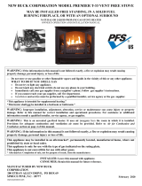
VENT-FREE FREESTANDING PEDESTAL STOVE SYSTEM
OWNER’S OPERATION AND INSTALLATION MANUAL
THERMOSTATICALLY - CONTROLLED MODELS
CFS26NT, CFS26PT, S26PTA AND S26NTA
20,000 TO 26,000 BTU/HR

www.desatech.com
110361-01K2
SAFETY
alteration, service or
maintenance can cause
-
for correct installation
-
additional information
-
WARNING: This is an
-
from the room in which
and ventilation air must
Air
for Combustion and Ven-
tilation
-
stalled in an aftermarket,*
-
chemicals known to the state
of California to cause cancer or
-
TABLE OF CONTENTS
Safety .................................................................. 2
Product Identication ........................................... 4
Local Codes......................................................... 5
Unpacking............................................................ 5
Product Features ................................................. 5
Air For Combustion And Ventilation ..................... 5
Installation ........................................................... 8
Operation ........................................................... 14
Inspecting Burners............................................. 15
Cleaning and Maintenance ................................ 16
Technical Service............................................... 17
Service Hints ..................................................... 17
Specications .................................................... 17
Troubleshooting ................................................. 18
Parts .................................................................. 22
Replacement Parts ............................................ 26
Accessories ....................................................... 26
Parts Central...................................................... 27
Warranty ..............................................Back Cover

www.desatech.com
110361-01K 3
Early signs
of carbon monoxide poisoning resemble the
u, with headaches, dizziness or nausea. If
you have these signs, the replace may not
be working properly.
Have replace serviced. Some people are
more affected by carbon monoxide than oth-
ers. These include pregnant women, people
with heart or lung disease or anemia, those
under the inuence of alcohol and those at
high altitudes.
Natural and
Propane/LP gases are odorless. An odor-
making agent is added to these gases. The
odor helps you detect a gas leak. However,
the odor added to the gas can fade. Gas may
be present even though no odor exists.
Make certain you read and understand all
warnings. Keep this manual for reference. It
is your guide to safe and proper operation of
this replace.
WARNING: Do not use a
-
WARNING: Do not allow fans
SAFETY
Continued
and adults away from hot sur-
-
dren when they are in the room
Make sure heater screen is in
-
-
1. This appliance is only for use with the type
of gas indicated on the rating plate. This
appliance is not convertible for use with
other gases.
2. Do not place propane/LP supply tank(s)
inside any structure. Locate propane/LP
supply tank(s) outdoors (propane/LP gas
units only).
3. If you smell gas
• shut off gas supply
• do not try to light any appliance
• do not touch any electrical switch; do not
use any phone in your building
• immediately call your gas supplier from
a neighbor’s phone. Follow the gas
supplier’s instructions
• if you cannot reach your gas supplier,
call the re department
4. This heater shall not be installed in a
bedroom or bathroom.

www.desatech.com
110361-01K4
SAFETY
Continued
if not enough fresh air is available. See Air
for Combustion and Ventilation, page 5.
If heater keeps shutting off, see Trouble-
shooting, page 18.
12. Keep all air openings in front and bottom
of heater clear and free of debris. This will
insure enough air for proper combustion.
13. Do not run heater
• where ammable liquids or vapors are
used or stored.
• under dusty conditions.
14. Do not use this heater to cook food or burn
paper or other objects.
15. Do not use heater if any part has been
under water. Immediately call a qualied
service technician to inspect the room
heater and to replace any part of the
control system and any gas control which
has been under water.
16. Turn off and unplug heater and let cool
before servicing. Only a qualied service
person should service and repair heater.
17. Operating heater above elevations of
4,500 feet could cause pilot outage.
18. Do not operate heater if any log is broken.
Do not operate heater if a log is chipped
(dime-sized or larger).
19. To prevent performance problems with
propane/LP units, do not use propane/LP
fuel tank of less than 100 lb. capacity.
20. Provide adequate clearances around air
openings.
Heater Controls
(Inside Door)
Screen
Logs
Stove
Cabinet
Figure 1 - Vent-Free Freestanding Pedestal Stove
5. Do not use this heater as a wood burning
heater. Use only the logs provided with the
heater.
6. Do not add extra logs or ornaments such
as pine cones, vermiculite or rock wool.
Using these added items can cause soot-
ing. Do not add lava rock around base.
Rock and debris could fall into the control
area of heater. After servicing, always
replace screen before operating heater.
7. You must operate this heater with the
heater screen in place. Make sure heater
screen is in place before running heater.
8. This heater is designed to be smokeless. If
logs ever appear to smoke, turn off heater
and call a qualied service person.
Note: During initial operation, slight smok-
ing could occur due to log curing and
heater burning manufacturing residues.
9. To prevent the creation of soot, follow the
instructions in Cleaning and Maintenance,
page 16.
10. Before using furniture polish, wax, carpet
cleaner or similar products, turn heater off. If
heated, the vapors from these products may
create a white powder residue within burner
box or on adjacent walls or furniture.
11. This heater needs fresh air ventilation to
run properly. This heater has an Oxygen
Depletion Sensing (ODS) safety shutoff
system. The ODS shuts down the heater
PRODUCT IDENTIFICATION

www.desatech.com
110361-01K 5
LOCAL CODES
their homes as airtight as possible.
While it is good to make your home energy
efcient, your home needs to breathe. Fresh
air must enter your home. All fuel-burning ap-
pliances need fresh air for proper combustion
and ventilation.
Exhaust fans, replaces, clothes dryers and
fuel burning appliances draw air from the house
to operate. You must provide adequate fresh
air for these appliances. This will insure proper
venting of vented fuel-burning appliances.
The following are excerpts from National Fuel
Gas Code, ANSI Z223.1/NFPA 54, Air for
Combustion and Ventilation.
All spaces in homes fall into one of the three
following ventilation classications:
1. Unusually Tight Construction
2. Unconned Space
3. Conned Space
Install and use heater with care. Follow all
local codes. In the absence of local codes,
use the latest edition of The National Fuel
Gas Code, ANSI Z223.1/NFPA 54*.
*Available from:
American National Standards Institute, Inc.
1430 Broadway
New York, NY 10018
National Fire Protection Association, Inc.
Batterymarch Park
Quincy, MA 02269
State of Massachusetts: The installation
must be made by a licensed plumber or
gas tter in the Commonwealth of Mas-
sachusetts.
Sellers of unvented propane or natural
gas-red supplemental room heaters shall
provide to each purchaser a copy of 527
CMR 30 upon sale of the unit.
Vent-free gas products are prohibited for
bedroom and bathroom installation in the
Commonwealth of Massachusetts.
UNPACKING
1. Remove top inner pack.
2. Tilt carton so that stove is upright.
3. Remove protective side packaging.
4. Slide stove out of carton.
5. Remove protective plastic wrap.
6. Remove screen by lifting and then pulling
forward.
7. Remove log set by cutting plastic ties.
8. Carefully unwrap log.
9. Check heater for any shipping damage.
If stove is damaged call DESA Heating,
LLC at 1-866-672-6040 for replacement
parts before returning to dealer.
PRODUCT FEATURES
This heater has a pilot with an Oxygen Deple-
tion Sensing (ODS) safety shutoff system. The
ODS/pilot is a required feature for vent-free
room heaters. The ODS/pilot shuts off the
heater if there is not enough fresh air.
This heater has a piezo ignitor. This system re-
quires no matches, batteries or other sources
to light heater.
AIR FOR COMBUSTION AND VENTILATION
WARNING: This heater shall
-
National Fuel Gas Code, ANSI
Z223.1/NFPA 54, the International
Fuel Gas Code,-
-
Today’s homes are built more energy efcient
than ever. New materials, increased insulation
and new construction methods help reduce
heat loss in homes. Home owners weather
strip and caulk around windows and doors
to keep the cold air out and the warm air in.
During heating months, home owners want

www.desatech.com
110361-01K6
The information on pages 5 through 7 will help
you classify your space and provide adequate
ventilation.
The air that leaks around doors and windows
may provide enough fresh air for combustion
and ventilation. However, in buildings of un-
usually tight construction, you must provide
additional fresh air.
construction where:
-
2
and
and
If your home meets all of these three criteria,
Ventilation Air From Outdoors
your home does not meet all of the three
Determining
Fresh-Air Flow For Fireplace Location
The National Fuel Gas Code, ANSI Z223.1/
NFPA 54 denes a conned space as a space
whose volume is less than 50 cubic feet per
1,000 Btu/hr (4.8 m
3
per kw) of the aggregate
input rating of all appliances installed in that
space and an unconned space as a space
whose volume is not less than 50 cubic feet per
1,000 Btu/hr (4.8 m
3
per kw) of the aggregate
input rating of all appliances installed in that
space. Rooms communicating directly with the
space in which the appliances are installed*,
through openings not furnished with doors, are
considered a part of the unconned space.
* Adjoining rooms are communicating only if
there are doorless passageways or ventilation
grills between them.
AIR FOR COMBUSTION AND VENTILATION
Continued
DETERMINING FRESH-AIR FLOW
FOR HEATER LOCATION
Use this work sheet to determine if you have
a conned or unconned space.
Includes the room in which you will install
heater plus any adjoining rooms with doorless pas-
sageways or ventilation grills between the rooms.
1. Determine the volume of the space (length
x width x height).
Length x Width x Height =__________cu. ft.
(volume of space)
Example: Space size 20 ft. (length) x 16 ft.
(width) x 8 ft. (ceiling height) = 2560 cu. ft.
(volume of space)
If additional ventilation to adjoining room
is supplied with grills or openings, add the
volume of these rooms to the total volume
of the space.
2. Multiply the space volume by 20 to determine
the maximum Btu/Hr the space can support.
________ (volume of space) x 20 = (Maxi-
mum Btu/Hr the space can support)
Example: 2560 cu. ft. (volume of space) x 20
= 51,200 (maximum Btu/Hr the space can
support)
3. Add the Btu/Hr of all fuel burning appliances
in the space.
Vent-free replace __________ Btu/Hr
Gas water heater* __________ Btu/Hr
Gas furnace __________ Btu/Hr
Vented gas heater __________ Btu/Hr
Gas replace logs __________ Btu/Hr
Other gas appliances* + _________ Btu/Hr
Total = ________ Btu/Hr
* Do not include direct-vent gas appliances.
Direct-vent draws combustion air from the
outdoors and vents to the outdoors.
Example:
Gas water heater __________ Btu/Hr
Vent-free replace + _________ Btu/Hr
Total = _________ Btu/Hr
4.
Compare the maximum Btu/Hr the space can
support with the actual amount of Btu/Hr used.
_______ Btu/Hr (maximum the space can
support)
_______ Btu/Hr (actual amount used)
Example: 51,200 Btu/Hr (maximum the
space can support)
56,000 Btu/Hr (actual amount of
Btu/Hr used)
30,000
26,000
56,000

www.desatech.com
110361-01K 7
The space in the above example is a conned
space because the actual Btu/Hr used is more
than the maximum Btu/Hr the space can sup-
port. You must provide additional fresh air. Your
options are as follows:
A. Rework worksheet, adding the space of an
adjoining room. If the extra space provides
an unconned space, remove door to adjoin-
ing room or add ventilation grills between
rooms. See Ventilation Air From Inside
Building.
B. Vent room directly to the outdoors. See
Ventilation Air From Outdoors.
C. Install a lower Btu/Hr heater, if lower Btu/Hr
size makes room unconned.
If the actual Btu/Hr used is less than the maxi-
mum Btu/Hr the space can support, the space is
an unconned space. You will need no additional
fresh air ventilation.
WARNING: If the area in which
-
National Fuel
Gas Code, ANSI Z223.1/NFPA 54,
the International Fuel Gas Code,
This fresh air would come from an adjoining
unconfined space. When ventilating to an
adjoining unconned space, you must provide
two permanent openings: one within 12" of the
ceiling and one within 12" of the oor on the
wall connecting the two spaces (see options
1 and 2, Figure 2). You can also remove door
into adjoining room (see option 3, Figure 2).
Follow the National Fuel Gas Code, ANSI
Z223.1/NFPA 54, Air for Combustion and
Ventilation for required size of ventilation grills
or ducts.
AIR FOR COMBUSTION AND VENTILATION
Continued
Provide extra fresh air by using ventilation
grills or ducts. You must provide two perma-
nent openings: one within 12" of the ceiling
and one within 12" of the oor. Connect these
items directly to the outdoors or spaces open
to the outdoors. These spaces include attics
and crawl spaces. Follow the National Fuel
Gas Code, ANSI Z223.1/NFPA 54, Air for
Combustion and Ventilation for required size
of ventilation grills or ducts.
IMPORTANT: Do not provide openings for
inlet or outlet air into attic if attic has a thermo-
stat-controlled power vent. Heated air entering
the attic will activate the power vent.
Figure 3 - Ventilation Air from Outdoors
Figure 2 - Ventilation Air from Inside
Building
Outlet
Air
V e ntilated
Attic
Outlet
Air
Inlet
Air
Inlet Air
V e ntilated
Crawl Space
T o
Crawl
Space
T o Attic
Or
Remove
Door into
Adjoining
Room,
Option
3
Ventilation Grills
Into Adjoining Room,
Option 2
Ventilation
Grills Into
Adjoining
Room,
Option 1
12"
12"

www.desatech.com
110361-01K8
IMPORTANT: Vent-free heaters add moisture
to the air. Although this is benecial, installing
heater in rooms without enough ventilation
air may cause mildew to form from too much
moisture. See Air for Combustion and Ventila-
tion, page 5.
Use correct gas type (natural or propane/LP).
If your gas supply is not correct, do not install
heater. Call dealer where you bought heater
for proper type heater.
-
WARNING: Maintain the
Carefully follow the instructions below. This
stove is a freestanding unit designed to set
directly on the oor. IMPORTANT: You must
maintain minimum wall and ceiling clearances
during installation. The minimum clearances
are shown in Figure 4, page 9. Measure from
outermost point of stove top.
A. Clearances from outermost point of stove
top to any combustible side wall should
not be less than 12".
B. Clearances from outermost point of stove
top to any combustible back wall should
not be less than 6" (Includes corner instal-
lations).
C. Clearances from the stove top to the ceil-
ing should not be less than 48".
INSTALLATION
NOTICE: This heater is intended
-
-
WARNING: Never install the
heater
CAUTION: This heater creates
move heat to wall surfaces next
-

www.desatech.com
110361-01K 9
6"
Minimum
48"
Minimum
Ceiling
Floor
Back Wall
Corner
Wall
Wall
6 "
Minimum
6 "
Minimum
12"
Minimum
12"
Minimum
48"
Minimum
Ceiling
Side Wall Side Wall
Figure 4 - Minimum Clearance to Walls and Ceiling
Front of Stove
Unit 42"
Front of
Stove
Unit 42"
Back Wall
Side
Wall
Side
Wall
12 "
Minimum
12 "
Minimum
6 "
Minimum
-
CAUTION: Never connect
-
WARNING: Never connect
INSTALLATION
Continued
Installation Items Needed
Before installing heater, make sure you have
the items listed below.
• piping (check local codes)
• sealant (resistant to propane/LP gas)
• equipment shutoff valve *
• test gauge connection *
• sediment trap
• tee joint
• pipe wrench
* An CSA design-certied equipment shutoff
valve with 1/8" NPT tap is an acceptable al-
ternative to test gauge connection. Purchase
the optional CSA design-certied equipment
shutoff valve from your dealer. See Acces-
sories, page 26.
For propane/LP units, the installer must supply
an external regulator. The external regulator
will reduce incoming gas pressure. You must
reduce incoming gas pressure to between 11"
and 14" of water. If you do not reduce incom-
ing gas pressure, heater regulator damage
could occur. Install external regulator with
the vent pointing down as shown in Figure 6.
Pointing the vent down protects it from freez-
ing rain or sleet.

www.desatech.com
110361-01K10
We recommend that you install a sediment
trap in supply line as shown in Figure 7.
Locate sediment trap where it is within reach
for cleaning. Install in piping system between
fuel supply and heater. Locate sediment
trap where trapped matter is not likely to
freeze. A sediment trap traps moisture and
contaminants. This keeps them from going
into heater controls. If sediment trap is not
installed or is installed wrong, heater may
not run properly.
INSTALLATION
Continued
From External Regulator
(11" W.C.** to 14" W.C.
Pressure)
Natural
From Gas Meter
(5" W.C.** to
10.5" W.C.
Pressure)
CSA Design-
Certied Equipment
Shutoff Valve With
1/8" NPT Tap*
Figure 7 - Gas Connection
* Purchase the optional CSA design-certied
equipment shutoff valve from your dealer. See
Accessories, page 26.
** Minimum inlet pressure for purpose of input
adjustment.
Tee
Joint
Pipe
Nipple
Cap
3"
Min
Sediment Trap
Gas
Regulator
of Heater
Approved
Flexible Gas
Hose (if allowed
by local codes)
Figure 5 - Gas Regulator Location and
Gas Line Access Into Stove Cabinet
Front of
Stove
Unit
Gas Regulator Inlet Connection
6"
Minimum
48"
Minimum
Ceiling
Floor
Back Wall
Figure 6 - External Regulator With Vent
Pointing Down
-
Installation must include an equipment shutoff
valve, union and plugged 1/8" NPT tap. Locate
NPT tap within reach for test gauge hook up.
NPT tap must be upstream from heater (see
Figure 7).
IMPORTANT: Install equipment shutoff valve
in an accessible location. The equipment
shutoff valve is for turning on or shutting off
the gas to the appliance.
Check building codes for any special require-
ments for locating equipment shutoff valve to
replaces.
Apply pipe joint sealant lightly to male NPT
threads. This will prevent excess sealant from
going into pipe. Excess sealant in pipe could
result in clogged heater valves.
External
Regulator
with Vent
Pointing
Down
Propane/LP
Supply Tank

www.desatech.com
110361-01K 11
INSTALLATION
Continued
and connections, internal and
external or unit, for leaks after
CAUTION: Make sure exter-
Con-
necting to Gas Supply
1. Disconnect heater with its appliance main
gas valve (control valve) and equipment
shutoff valve from gas supply piping sys-
tem. Pressures in excess of 1/2 psig will
damage heater regulator.
2. Cap off open end of gas pipe where equip-
ment shutoff valve was connected.
3. Pressurize supply piping system by either
opening propane/LP supply tank valve for
propane/LP gas, opening main gas valve
located on or near gas meter for natural
gas or using compressed air.
4. Check all joints of gas supply piping system.
Apply noncorrosive leak detection uid to
gas joints. Bubbles forming show a leak.
5. Correct all leaks at once.
6. Reconnect heater and equipment shutoff
valve to gas supply. Check reconnected
ttings for leaks.
1.
Close equipment shutoff valve (see Figure 8).
2. Pressurize supply piping system by either
opening propane/LP supply tank valve for
propane/LP gas, opening main gas valve
located on or near gas meter for natural
gas or using compressed air.
3. Check all joints from gas meter to equip-
ment shutoff valve (see Figures 9 and 10).
Apply noncorrosive leak detection uid to
gas joints. Bubbles forming show a leak.
4. Correct all leaks at once.
CONNECTIONS
1.
Open equipment shutoff valve (see Figure 8).
2. Open main gas valve located on or near
gas meter for natural gas or open propane/
LP supply tank valve for propane/LP gas.
3. Make sure control knob of heater is in the
OFF position.
4.
Check all joints from equipment shutoff valve
to control valve (see Figures 9 and 10). Ap-
ply noncorrosive leak detection uid to gas
joints. Bubbles forming show a leak.
5. Correct all leaks at once.
6. Light heater (see Operation, page 14).
Check all other internal joints for leaks.
7. Turn off heater (see To Turn Off Gas to
Appliance, page 15).
Figure 8- Equipment Shutoff Valve
Figure 9 - Checking Gas Joints
Control Valve
Location
Propane/LP
Supply Tank
Equipment Shutoff Valve
Figure 10 - Checking Gas Joints
Gas Meter
Equipment
Shutoff
Valve
Control Valve
Location
Open
Closed
Equipment
Shutoff Valve

www.desatech.com
110361-01K12
INSTALLATION
Continued
Figure 12 - Installing One-Piece Log set
(Top View)
One Piece
Log Set
Burner Ports
Tools required: Phillips screwdriver
1. Remove top panel of stove by removing
3 screws from under top lip on each side
of stove (see Figure 13).
2. Facing front of stove, carefully slide top
panel forward until it is completely re-
moved from stove (see Figure 13).
3. Disconnect power cord wires from blower
motor (if connected) (see Figure 14).
4. Disconnect green ground wire from blower
housing (if connected) by removing screw
holding wire terminal (see Figure 14).
5. Install one plastic bushing provided in
blower kit into the 1
1
/
2
" hole in left rear of
rebox oor. Access hole through rectangu-
lar opening in rear panel (see Figure 15).
6. Remove two blower mounting brackets
from rear panel by removing two screws
each (see Figure 16).
Figure 13 - Removing Stove Top Panel
Figure 14 - Removing Wires from Blower
Figure 15 - Installing Bushing
Screw
Green Ground Wire
White Power
Cord Wire
Black Power Cord Wire
Bushing
INSTALLING LOGS
CAUTION: After installation
It is very important to install the logs exactly
as instructed. Do not modify logs. Only use
logs supplied with heater.
Place one-piece log set on grate to t as il-
lustrated in Figure 11. Make sure log sits at
on rebox oor (see Figure 11).
IMPORTANT: Make sure log does not cover
any burner ports (see Figure 12).
Figure 11 - Installing One-Piece Log Set
One Piece
Log Set
Firebox
Floor

www.desatech.com
110361-01K 13
INSTALLATION
Continued
7. Attach 2 mounting brackets to blower
housing using 4 screws provided in blower
kit (2 for each bracket) (see Figure 16).
Tighten screws securely. Place blower
assembly temporarily on top of rebox.
8. Working from rear of stove, place entire
power cord, including speed control hous-
ing, in lower control compartment.
9. Route ends of 3-wire power cord up from
lower control compartment through plastic
bushing, then up to upper cavity of stove
(see Figure 17).
10. Attach terminal ends of white and black
power cord wires to terminals on blower mo-
tor (see Figure 14, page 12). Push rmly.
11. Attach terminal end of green power cord
wire to front tab of blower housing using
screw provided (see Figure 14, page 12).
12. Using the 4 screws previously removed,
mount blower assembly to stove by reat-
taching blower brackets to rear panel (see
Figure 16). Tighten screws securely.
13. Install plastic control knob onto output
shaft of speed control housing (see Fig-
ure 17). Place speed control housing just
inside control compartment door in front
of stove (see Figure 17).
14. Using 2 screws provided in blower kit,
mount blower speed control housing to
mounting tab in left side of lower control
compartment (see Figure 18).
15. Check to make sure that power cord is
completely clear of blower wheel and there
are no foreign objects in blower wheel.
16. Carefully replace stove top panel. Align
holes and replace 6 screws removed in
step 1, page 12.
17. Peel off backing paper and stick supplied
wiring diagram decal on stove oor as
shown in Figure 18.
18. Plug power cord into a convenient 3-prong
grounded wall receptacle near the stove.
Figure 16 - Removing Blower Brackets
from Stove and Attaching to Blower
Blower
Blower Bracket
Firebox
Top
WARNING: Electrical Ground-
19. Using speed control knob, turn blower on
and check for operation.
20. All remaining parts from blower kit may
be discarded.
Figure 17 - Installing Blower Control Housing
Power
Cord
Speed
Control
Housing
Control
Knob
Figure 18 - Routing Power Cord
Blower Speed
Control Housing
Wiring Diagram Decal
V a riable
Fan Switch
WhiteWhite
Black
Green
On
1 1 0/115
V . A.C.
Blower
Motor
Black
Black
Black
Off
120 Vac.
60 Hz. .
78 Amps
If any of the original wire as supplied with appliance must be re-
placed, it must be replaced with 105°C wire or it’s equivalent.
-
DESA Heating Products, Bowling Green, KY

www.desatech.com
110361-01K14
OPERATION
3. Turn control knob clockwise to the
OFF position.
4. Wait ve (5) minutes to clear out any gas.
Then smell for gas, including near the
oor. If you smell gas, STOP! Follow “B”
in the safety information, column 1. If you
don’t smell gas, go to the next step.
5. Turn control knob counterclockwise
to the PILOT position. Press in control knob
for ve (5) seconds (see Figure 19).
Note: You may be running this heater for
the rst time after hooking up to gas sup-
ply. If so, the control knob may need to be
pressed in for 30 seconds or more. This will
allow air to bleed from the gas system.
6.
With control knob pressed in, press and
release ignitor button. This will light pilot. The
pilot is attached to the front burner. If needed,
keep pressing ignitor button until pilot lights.
Note: If pilot does not stay lit, contact a
qualied service person or gas supplier for
repairs. Until repairs are made, light pilot
with match. To light pilot with match, see
Manual Lighting Procedure, page 15.
7. Keep control knob pressed in for 30 sec-
onds after lighting pilot. After 30 seconds,
release control knob.
• If control knob does not pop out when
released, contact a qualified service
person or gas supplier for repairs.
Note: If pilot goes out, repeat steps 3
through 7. This heater has a safety inter-
lock system. Wait one (1) minute for sys-
tem to reset before lighting pilot again.
8. Turn control knob counterclockwise
to desired heating level. The burners
should light. Set control knob to any heat
level between HI and LO.
Figure 20 - Pilot
Figure 19 - Control Knob and Ignitor
Button Location
Control Knob
Ignitor Button
Thermocouple
Pilot Burner
Ignitor Electrode
FOR YOUR SAFETY
WARNING: If you do not fol-
low these instructions exactly,
-
-
WHAT TO DO IF YOU SMELL GAS
-
LIGHTING
INSTRUCTIONS
-
1. STOP! Read the safety information,
above.
2. Make sure equipment shutoff valve is fully
open.

www.desatech.com
110361-01K 15
OPERATION
Continued
INSPECTING BURNERS
9. To leave pilot lit and shut off burners only,
turn control knob clockwise to the
PILOT position.
CAUTION: Do not try to ad-
TO TURN OFF GAS
1. Turn control knob clockwise to the
OFF position.
2 . Close equipment shutoff valve (see Figure
8, page 11).
THERMOSTAT CONTROL
The thermostat control knob can be set to any
comfort level between HI and LO. The ther-
Note: The correct pilot ame on natural gas
units will have a slight curve, but ame should
be blue an have no yellow or orange color.
Figure 23 shows a correct burner ame pattern.
Figure 24 shows an incorrect burner ame pat-
tern. If burner ame pattern is incorrect,
•
turn heater off (see To Turn Off Gas to Appliance)
• see Troubleshooting, page 18
Figure 21 - Correct Pilot Flame Pattern
(Natural Gas Shown)
Figure 22 - Incorrect Pilot Flame Pattern
(Natural Gas Shown)
Thermocouple
Pilot Burner
Thermocouple
Pilot
Burner
Figure 23 - Correct Flame Pattern with
Control Knob Set to High Flame
Figure 24 - Incorrect Flame Pattern with
Control Knob Set to High Flame
Approx.
3-6"
Above
Top of
Logs
More
Than 8"
Above
Top of
Logs
mostat will gradually modulate the heat output
and ame height from higher to lower settings
or pilot, in order to maintain the comfort level
you select. The ideal comfort setting will vary
by household depending upon the amount of
space to be heated, the output of the central
heating system, etc.
Note: Selecting the HI setting with the control
knob will cause the burners to remain fully on,
without modulating down in most cases.
MANUAL LIGHTING
1. Follow steps 1 through 5 under Lighting
Instructions, page 14.
2.
Press control knob and light pilot with match.
3. Keep control knob pressed in for 30 sec-
onds after lighting pilot. After 30 seconds,
release control knob. Now follow step 8
Lighting Instructions, page 14
Check pilot ame pattern and burner ame
patterns often.
Figure 21 shows a correct pilot ame pattern.
Figure 22 shows an incorrect pilot ame pat-
tern. The incorrect pilot ame is not touching
the thermocouple. This will cause the thermo-
couple to cool. When the thermocouple cools,
the heater will shut down.
If pilot ame pattern is incorrect, as shown
in Figure 22
•
turn heater off (see To Turn Off Gas to Appliance)
• see Troubleshooting, page 18

www.desatech.com
110361-01K16
CLEANING AND MAINTENANCE
3. Blow air through the ports/slots and holes
in the burner.
4. Check the injector holder located at the
end of the burner tube again. Remove
any large particles of dust, dirt, lint or pet
hair with a soft cloth or vacuum cleaner
nozzle.
5. Blow air into the primary air holes on the
injector holder.
6. In case any large clumps of dust have now
been pushed into the burner repeat steps
3 and 4.
Clean the pilot assembly also. A yellow tip on
the pilot ame indicates dust and dirt in the
pilot assembly. There is a small pilot air inlet
hole about 2" from where the pilot ame comes
out of the pilot assembly (see Figure 26). With
the unit off, lightly blow air through the air inlet
hole. You may blow through a drinking straw
if compressed air is not available.
Figure 25 - Injector Holder On Outlet
Burner Tube
Figure 26 - Pilot Inlet Air Hole
Burner
Tube
Pilot
Assembly
Pilot Air
Inlet Hole
Ports/Slots
Burner
Tube
Injector Holder (May
Be Brass or Aluminum
Depending on Model)
Primary Air Inlet Holes (Shape
of Holes May Vary by Model)
WARNING: Turn off heater
-
-
The primary air inlet holes allow the proper
amount of air to mix with the gas. This pro-
vides a clean burning flame. Keep these
holes clear of dust, dirt, lint and pet hair.
Clean these air inlet holes prior to each
heating season. Blocked air holes will create
soot. We recommend that you clean the unit
every three months during operation and
have heater inspected yearly by a qualied
service person.
We also recommend that you keep the burner
tube and pilot assembly clean and free of dust
and dirt. To clean these parts we recommend
using compressed air no greater than 30 PSI.
Your local computer store, hardware store or
home center may carry compressed air in a
can. If using compressed air in a can, please
follow the directions on the can. If you don’t
follow directions on the can, you could dam-
age the pilot assembly.
1. Shut off unit, including pilot. Allow unit to
cool for at least thirty minutes.
2. Inspect burner, pilot and primary air inlet
holes on injector holder for dust and dirt
(see Figure 25).

www.desatech.com
110361-01K 17
Use a vacuum cleaner or pressurized air to
clean.
Exterior
Use a soft cloth dampened with a mild soap
and water mixture. Wipe the cabinet to re-
move dust.
LOGS
• If you remove logs for cleaning, refer to
Installing Logs, page 12, to properly replace
logs.
• Replace log(s) if broken or chipped (dime-
sized or larger).
CLEANING AND MAINTENANCE
Continued
SPECIFICATIONS
TECHNICAL SERVICE
You may have further questions about installa-
tion, operation, or troubleshooting. If so, con-
tact DESA Heating, LLC at 1-866-672-6040.
When calling please have your model and
serial numbers of your heater ready.
You can also visit DESA Heating, LLC’s web
site at .
Periodically inspect all burner ame holes with
the heater running. All slotted burner ame
holes should be open with yellow ame pres-
ent. All round burner ame holes should be
open with a small blue ame present. Some
burner ame holes may become blocked by
debris or rust, with no ame present. If so,
turn off heater and let cool. Remove blockage.
Blocked burner ame holes will create soot.
SERVICE HINTS
• pilot will not stay lit
• burners will have delayed ignition
• heater will not produce specied heat
• propane/LP gas supply may be low
You may feel your gas pressure is too low. If
so, contact your local gas supplier.
• Rating: 20,000/26,000 Btu/hr (Variable)
• Type Gas: Propane/LP Only
• Ignition: Piezo
• Manifold Pressure: 8" W.C.
• Inlet Gas Pressure (in. of water) *:
Maximum 14" W.C., Minimum 11" W.C.
• Dimensions (H x W x D):
Stove 24" x 27
1
/
4
" x 17
1
/
4
"
Carton 22" x 31" x 31
1
/
2
"
• Weight: Stove 66 lbs., Shipping 80 lbs.
• Rating: 20,000/26,000 Btu/hr (Variable)
• Type Gas: Natural Only
• Ignition: Piezo
• Manifold Pressure: 3" W.C.
• Inlet Gas Pressure (in. of water) *:
Maximum 10.5" W.C., Minimum 5" W.C.
• Dimensions (H x W x D):
Stove 24" x 27
1
/
4
" x 17
1
/
4
"
Carton 22" x 31" x 31
1
/
2
"
• Weight: Stove 66 lbs., Shipping 80 lbs.
* For purposes of input adjustment

www.desatech.com
110361-01K18
TROUBLESHOOTING
Note: All troubleshooting items are listed in order of operation.
1. Ignitor electrode not con-
nected to ignitor cable
2. Ignitor cable pinched or
wet
3. Piezo ignitor nut is loose
4. Broken ignitor cable
5. Bad piezo ignitor
6. Ignitor electrode broken
7. Ignitor electrode positioned
wrong
1. Gas supply turned off or
equipment shutoff valve
closed
2. Control knob not in PILOT
position
3. Control knob not pressed in
while in PILOT position
4. Air in gas lines when in-
stalled
5. Depleted gas supply, pro-
pane/LP only
6. ODS/pilot is clogged
7. Gas regulator setting is not
correct
REMEDY
1. Reconnect ignitor cable
2. Free ignitor cable if pinched
by any metal or tubing.
Keep ignitor cable dry
3. Tighten nut holding piezo
ignitor to base panel of log
set. Nut is located behind
base panel
4. Replace ignitor cable
5. Replace piezo ignitor
6. Replace pilot assembly
7. Replace pilot assembly
1. Turn on gas supply or open
equipment shutoff valve
2. Turn control knob to PILOT
position
3. Press in control knob while
in PILOT position
4. Continue holding down
control knob. Repeat ignit-
ing operation until air is
removed
5. Contact local propane/LP
gas company
6. Clean ODS/p i lot ( s ee
Cleaning and Maintenance,
page 16) or replace ODS/
pilot assembly
7. Replace gas control
When ignitor button is
pressed, there is no spark
at ODS/pilot
When ignitor button is
pressed, there is spark at
ODS/pilot but no ignition

www.desatech.com
110361-01K 19
TROUBLESHOOTING
Continued
1. Contr ol knob not fully
pressed in
2. Control knob not pressed in
long enough
3. Equipment shutoff valve not
fully open
4. Pilot flame not touching
thermocouple, which al-
lows thermocouple to cool,
causing pilot ame to go
out. This problem could be
caused by one or both of
the following:
A) Low gas pressure
B) Dirty or partially clogged
ODS/pilot
5. Thermocouple connection
loose at control valve
6. Thermocouple damaged
7. Control valve damaged
1. Burner orice clogged
2. Inlet gas pressure is too
low
3.
Thermopile leads disconnect-
ed or improperly connected
4. Burners will not come on in
remote position
1. Manifold pressure is too
low
2. Burner orice clogged
1. Burner orice is clogged or
damaged
2. Damaged burner
3. Gas regulator defective
1. Not enough air
2. Gas regulator defective
3. Residues from manufac-
turing processes and logs
curing
REMEDY
1. Press in control knob fully
2. After ODS/pilot lights, keep
control knob pressed in 30
seconds
3. Fully open equipment shut-
off valve
4. A) Contact local gas com-
pany
B) Clean ODS/pilot (see
Cleaning and Maintenance,
page 16) or replace ODS/
pilot assembly
5. Hand tighten until snug,
then tighten 1/4 turn more
6. Replace pilot assembly
7. Replace control valve
1. Clean burner (see Cleaning
and Maintenance, page 16)
or replace burner orice
2. Contact local gas com-
pany
3. Reconnect leads (see wir-
ing diagram)
4. Replace battery in transmit-
ter and receiver
1. Contact local gas com-
pany
2. Clean burner (see Cleaning
and Maintenance, page 16)
or replace burner orice
1. Clean burner (see Cleaning
and Maintenance, page 16)
or replace burner orice
2. Replace damaged burner
3. Replace gas control
1. Check burner for dirt and
debris. If found, clean
burner (see Cleaning and
Maintenance, page 16)
2. Replace gas control
3. Problem will stop after a few
hours of operation
ODS/pilot lights but ame
goes out when control knob
is released
Burner does not light after
ODS/pilot is lit
Delayed ignition burner
Burner backfiring during
combustion
Slight smoke or odor during
initial operation

www.desatech.com
110361-01K20
TROUBLESHOOTING
Continued
1. Not enough combustion/
ventilation air
1. Turning control knob to HI
position when burner is
cold
2. Air in gas line
3. Air passageways on heater
blocked
4. Dirty or partially clogged
burner orice
1. Improper log placement
2. Drafts or other air currents
affecting ame pattern
3. Air holes at burner inlet
blocked
4. B u r n e r f l a m e h o l e s
blocked
1. When heated, vapors from
furniture polish, wax, carpet
cleaners, etc. may turn into
white powder residue
1. Metal expanding while
heating or contracting while
cooling
REMEDY
1. Refer to Air for Combustion
and Ventilation require-
ments (page 5)
1. Turn control knob to LO
position and let warm up
for a minute
2. Operate burner until air is
removed from line. Have
gas line checked by local
gas company
3.
Observe minimum installation
clearances (see page 8)
4. Clean burner (see Cleaning
and Maintenance, page 16)
or replace burner orice
1. Properly locate logs (see
Installing Logs, page 12)
2. Eliminate source of drafts
around heater
3. Clean out air holes at burn-
er inlet. Periodically repeat
as needed
4. Remove blockage or re-
place burner
1. Turn heater off when us-
ing furniture polish, wax,
carpet cleaners or similar
products
1. This is normal with most
heaters. If noise is exces-
sive, contact qualied ser-
vice person
Moisture/condensation no-
ticed on windows
Heater produces a whistling
noise when burner is lit
Dark residue on logs or inside
of replace
White powder residue form-
ing within burner box or on
adjacent walls or furniture
Heater produces a clicking/
ticking noise just after burner
is lit or shut off
/