Page is loading ...

USER MANUAL
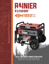
WGen7500DF
Dual Fuel Portable Generator
GASOLINE: 7500 Running Watts | 9500 Peak Watts
PROPANE: 6750 Running Watts | 8550 Peak Watts
REMOTE START
PUSH BUTTON
ELECTRIC START

2 | Westinghouse Portable Power
DISCLAIMERS:
All information, illustrations and specications in this manual are based on the latest information available at
the time of publishing. The illustrations used in this manual are intended as representative reference views only.
Moreover, because of our continuous product improvement policy, we may modify information, illustrations and/or
specications to explain and/or exemplify a product, service or maintenance improvement. We reserve the right
to make any change at any time without notice. Some images may vary depending upon which model is shown.
ALL RIGHTS RESERVED:
No part of this publication may be reproduced or used in any form by any means – graphic, electronic or
mechanical, including photocopying, recording, taping or information storage and retrieval systems – without the
written permission of MWE Investments LLC.
DANGER
This manual contains important instructions for operating this generator. For your safety
and the safety of others, be sure to read this manual thoroughly before operating the
generator. Failure to properly follow all instructions and precautions can cause you and
others to be seriously hurt or killed.
California
Proposition 65 Warning
The engine exhaust from this product
contains chemicals known to the state
of California to cause cancer, birth
defects or other reproductive harm.
California
Proposition 65 Warning
Certain components in this product and its
related accessories contain chemicals
known to the state of California to cause
cancer, birth defects or other reproductive
harm. Wash hands after handling.
Model
Number
Running
Watts
Peak
Watts
Fuel Tank
Size (G)
Rated
Speed
(RPM)
Ignition
Type
Spark
plug
Engine
Disp (cc)
Stroke X
Bore
Oil
Capacity
(L) Oil Type
WGen7500DF Gas:
7500
Propane:
6750
Gas:
9500
Propane:
8550
6.6 Gallons 3600 TCI F7TC 420cc 66X90 1.1 10W30
WGen TECHNICAL SPECIFICATIONS
HAVE QUESTIONS?
DO NOT RETURN THIS PRODUCT TO THE STORE
Email us at service@wpowereq.com
or call 1-855-944-3571
SAVE THESE INSTRUCTIONS
Important safety instructions are included in this manual.

Westinghouse Portable Power | 3
FOR YOUR RECORDS:
Date of Purchase:
Generator Model Number:
Purchased from Store/Dealer:
Generator Serial Number:
IMPORTANT: KEEP YOUR PURCHASE RECEIPT TO ENSURE TROUBLE-FREE WARRANTY
COVERAGE.
PRODUCT REGISTRATION
To ensure trouble-free warranty coverage, it is important you register your Westinghouse generator.
You can register your generator by either:
1. Filling in the product registration form below and mailing to:
Product Registration
MWE Investments LLC
777 Manor Park Drive
Columbus, Ohio 43228
2. Registering your product Online at www.westinghouseportablepower.com/register-your-product/
To register your generator you will need to locate the following information:
WESTINGHOUSE PRODUCT REGISTRATION FORM
PERSONAL INFORMATION GENERATOR INFORMATION
First Name: _______________________________________ Model Number: _____________________________________
Last Name: _______________________________________ Serial Number: ______________________________________
Street Address: ___________________________________ Date Purchased: ____________________________________
Street Address: ___________________________________ Purchased From: ____________________________________
City, State, ZIP: ____________________________________
Country: __________________________________________
Phone Number: ___________________________________
E-Mail: ___________________________________________
HAVE QUESTIONS?
DO NOT RETURN THIS PRODUCT TO THE STORE
Email us at service@wpowereq.com
or call 1-855-944-3571
Made in China/
Fabriqu é en Chine
CSA Master Contract
Number :
Numéro de contrat
principa l de CSA
MWE Investments LLC
Columbus Ohio 43228 USA
Con u à columbus , Ohio,tats-Unis
MWE Investments LLC
Columbus Ohio 43228 Etats-Unis
Par t N0.
Numéro de
pièc e
Designed in Columbus , Ohio USA

4 | Westinghouse Portable Power
TABLE OF CONTENTS
WGEN7500DF TECHNICAL SPECIFICATIONS .....2
PRODUCT REGISTRATION .....................3
For Your Records: ..........................3
Product Registration .......................3
Product Registration Form ...................3
SAFETY .....................................5
Safety Denitions ..........................5
Safety Symbol Denitions ...................5
General Safety Rules ........................6
Safety Labels and Decals ....................7
Fuel Safety ................................9
UNPACKING .................................10
What Comes in the Box ......................10
Wheel Kit Accessories Box ...................10
ASSEMBLY .................................11
Installing Wheels and Feet ....................11
Installing the Battery ........................12
FEATURES .................................13
Generator Features .........................13
Control Panel Features .....................15
OPERATION .................................16
Before Starting the Generator .................16
Location Selection .......................16
Grounding the Generator ..................16
High Altitude Operation/Conversion Kits ......16
Power Cord ..............................17
Using Extension Cords ...................17
Using Westinghouse Power Cord ...........17
Transfer Switch Connections ..................18
Engine Fluids and Fuel .......................19
Adding Gasoline to the Fuel Tank ...........19
Connecting the LPG/Propane Tank ..........19
Switching Fuel Sources ......................20
Starting the Generator ......................21
Starting on Gasoline .....................21
Starting on Propane .....................21
Push Button Start .......................21
Stopping the Generator ......................22
Normal Operation .......................22
During an Emergency ....................22
MAINTENANCE ..............................22
Maintenance Schedule ......................23
Engine Oil Maintenance .....................24
Engine Oil Specication ...................24
Checking Engine Oil .....................24
Adding Engine Oil .......................24
Changing Engine Oil .....................25
Air Filter Maintenance .......................25
Cleaning the Air Filter ....................25
Spark Plug Maintenance .....................26
Checking and Adjusting Valve Lash ..............27
Testing GFCI Outlets ........................27
Battery Service. . . . . . . . . . . . . . . . . . . . . . . . . . . . . 27
Battery Charger ..........................27
Battery Replacement .....................28
Cleaning the Generator ......................28
Storage ..................................28
TROUBLE SHOOTING .........................29
SCHEMATICS ................................31
WGen7500DF Schematic ....................31
EXPLODED AND ENGINE VIEWS ................32
WGen7500DF Exploded View .................32
WGen7500DF Engine View ...................34

Westinghouse Portable Power | 5
SAFETY DEFINITIONS
The words DANGER, WARNING, CAUTION and
NOTICE are used throughout this manual to highlight
important information. Be certain that the meanings of
these alerts are known to all who work on or near the
equipment.
This safety alert symbol appears
with most safety statements. It
means attention, become alert, your
safety is involved! Please read and
abide by the message that follows
the safety alerts symbol.
DANGER
Indicates a hazardous situation which, if not
avoided, will result in death or serious injury.
WARNING
Indicates a hazardous situation which, if not
avoided, could result in death or serious injury.
CAUTION
Indicates a hazardous situation which, if not
avoided, could result in minor or moderate injury.
NOTICE
Indicates a situation which can cause damage to the
generator, personal property and/or the environment,
or cause the equipment to operate improperly.
NOTE: Indicates a procedure, practice or condition
that should be followed in order for the
generator to function in the manner
intended.
SAFETY
SAFETY SYMBOL DEFINITIONS

6 | Westinghouse Portable Power
DANGER
Never use the generator in a location that is wet or damp. Never expose the generator to rain,
snow, water spray or standing water while in use. Protect the generator from all hazardous weather
conditions. Moisture or ice can cause a short circuit or other malfunction in the electrical circuit.
Never operate the generator in an enclosed area. Engine exhaust contains carbon monoxide. Only
operate the generator outside and away from windows, doors and vents.
WARNING
Voltage produced by the generator could result in death or serious injury.
• Never operate the generator in rain or a ood plain unless proper precautions are taken to avoid
being subject to rain or a ood.
• Never use worn or damaged extension cords.
• Always have a licensed electrician connect the generator to the utility circuit.
• Never touch an operating generator if the generator is wet or if you have wet hands.
• Never operate the generator in highly conductive areas such as around metal decking or steel
works.
• Always use grounded extension cords. Always use three-wire or double-insulated power tools.
• Never touch live terminals or bare wires while the generator is operating.
• Be sure the generator is properly grounded before operating.
WARNING
Gasoline, gasoline vapors & liquid petroleum gas (LPG) are extremely ammable and explosive
under certain conditions.
• Always refuel the generator outdoors, in a well-ventilated area.
• Never remove the fuel cap with the engine running.
• Never refuel the generator while the engine is running. Always turn engine o and allow the
generator to cool before refueling.
• Only ll fuel tank with gasoline.
• Keep sparks, open ames or other form of ignition (such as matches, cigarettes, static electric
sources) away when refueling.
• Never overll the fuel tank. Leave room for fuel to expand. Overlling the fuel tank can result in a
sudden overow of gasoline and result in spilled gasoline coming in contact with HOT surfaces.
Spilled fuel can ignite. If fuel is spilled on the generator, wipe up any spills immediately. Dispose
of rag properly. Allow area of spilled fuel to dry before operating the generator.
• Wear eye protection while refueling.
• Never use gasoline as a cleaning agent.
• Store any containers containing gasoline or propane in a well-ventilated area, away from any
combustibles or source of ignition.
• Check for fuel leaks after refueling. Never operate the engine if a fuel leak is discovered.
WARNING
Never operate the generator if powered items overheat,
electrical output drops, there is sparking, ames or smoke
coming from the generator, or if the receptacles are
damaged.
Never use the generator to power medical support
equipment.
Always remove any tools or other service equipment used
during maintenance from the generator before operating.
NOTICE
Never modify the generator.
Never operate the generator if it
vibrates at high levels, if engine
speed changes greatly or if the
engine misres often.
Always disconnect tools or
appliances from the
generator before starting.
GENERAL SAFETY RULES
SAFETY

Westinghouse Portable Power | 7
SAFETY
SAFETY LABELS AND DECALS
4
1
4
7
2
5
1
6
Made in China/
Fabriqu é en Chine
CSA Master Contract
Number :
Numéro de contrat
principa l de CSA
MWE Investments LLC
Columbus Ohio 43228 USA
Con u à columbus , Oh io,tats-Unis
MWE Investments LLC
Columbus Ohio 43228 Etats-Unis
Part N0.
Numéro de
pièce
Designed in Columbus , Ohio USA
Made in China/ Fabriqu é en Chine
CSA Master Contract
Number :
Numéro de contrat
principa l de CSA
MWE Investments LLC
Columbus Ohio 43228 USA
Con u à columbus , O hio,tats-Unis
MWE Investments LLC
Columbus Ohio 43228 Etats-Unis
Par t N0.
Numéro de
pièc e
Designed in Columbus , Ohio USA
2 5
6
4
7

8 | Westinghouse Portable Power
SAFETY
SAFETY LABELS AND DECALS
10
11
9
12
10
11
8
8
9
5
12

Westinghouse Portable Power | 9
When transporting or servicing the generator:
• Make certain the fuel shuto valve is o and the fuel
tank is empty.
• Make sure the LPG tank and LPG hose is not attached
to the generator.
• Disconnect the spark plug wire.
When storing the generator:
• Store away from sparks, open ames, pilot lights, heat
and other sources of ignition.
• Do not store gas or LPG tank near furnaces, water
heaters or any other appliances that produce heat or
have automatic ignitions.
CAUTION
Only use approved LPG tanks with
OPD (overlling prevention device)
valve. Always keep the tank in a
vertical position with the valve on
top and installed at ground level on a
at surface. Do not allow tanks to be
around any heat source and make sure
it is not exposed to the sun, rain and
dust. When transporting and storing,
turn o the tank valve and fuel valve,
and disconnect the tank. Make sure to
always cover the generator and tank
outlet with protective plastic caps.
CAUTION
Do not allow children to tamper or
play with the propane tank or hose
connections.
WARNING
If there is a strong smell of propane
while operating the generator close the
valve on the propane tank immediately.
Once the propane is o, use soapy
water to check for leaks on the hose
and connections on the tank valve and
the generator. Do not smoke or light a
cigarette or check for leaks using any
open ame source such as a match
or lighter. If a leak is found contact
a qualied technician to inspect and
repair the LPG system before using the
generator.
DANGER
Gasoline and liquid petroleum gas
(LPG) are highly explosive and
ammable. Explosions and re can
cause severe burns or death.
Gasoline and gasoline vapor (Gas)
• Gasoline is highly ammable and explosive.
• Gas expands and contracts with dierent
temperatures.
• In case of a gas re, do not attempt to extinguish the
ame if the fuel shuto valve is in the on position.
Introducing an extinguisher to a generator with an
open fuel valve could create an explosion hazard.
• Gas has a distinctive odor, this will help detect
potential leaks quickly.
• Gas vapors can cause a re if ignited.
• Gasoline is a skin irritant and needs to be cleaned up
immediately if it comes in contact with the skin.
Liquid Petroleum Gas (Propane/LPG)
• LPG/Propane is highly ammable and explosive.
• Flammable gas under pressure can cause a re or
explosion if ignited.
• LPG/Propane can settle in low places because it is
heavier than air.
• LPG/Propane has a distinctive odor added to help
detect potential leaks.
• Always keep LPG/Propane tank in an upright position.
• When exchanging LPG/Propane tanks, be sure the
tank value is the same type.
• In case of a LPG/Propane re, do not attempt to
extinguish unless the fuel supply can be shut o.
• LPG/Propane will burn the skin. Prevent skin contact
at all times.
WARNING
Never use a gas container, LPG
connector hose, LPG tank or any
other fuel item that appears to be
damaged.
When starting generator:
• Make sure that the gas cap, air lter, spark plug, fuel
lines and exhaust system are properly in place.
• If you spill any gasoline on the tank, allow it to fully
evaporate before operating.
• Make sure the generator and propane tank are on a
at surface before operating.
• If there is a propane odor do not start the unit because
there may be a potential leak.
• Never place propane tank near engine exhaust.
SAFETY
FUEL SAFETY

10 | Westinghouse Portable Power
1. Washer (2 used)
2. Flange Bolt M8 x16mm (4 used)
3. Hairpin Cotter Pin (2 used)
4. Wheel Axle Pin (2)
CAUTION
Always have assistance when lifting
the generator. The generator is heavy;
lifting it could cause bodily harm.
Avoid cutting on or near staples
to prevent personal injury.
Tools required – box cutter or similar device.
1. Carefully cut the packing tape on top of the carton.
2. Fold back top aps to reveal the manual.
3. Remove the Wheel Kit Accessories cardboard box.
4. Carefully cut two sides of the carton to
remove the generator.
WHAT COMES IN THE BOX
Manual
Quick Start Guide/Maintenance Schedule
LPG Hose (1)
Wireless Remote Starter (1)
1.1 Liter Bottle of SAE 10W30 Oil (1)
Spark Plug Socket Wrench (1)
Wheel Kit Accessories Box
Battery Charger (1)
Funnel (1)
WHEEL KIT ACCESSORIES BOX
Open the Wheel Kit Accessories box and verify the
contents against the list right. If any parts are missing,
contact our service team at [email protected] or
call 1-855-944-3571.
UNPACKING
Figure 1 -Wheel and Feet Kit Hardware
1
2
3
4

Westinghouse Portable Power | 11
INSTALLING WHEELS AND FEET
BEFORE ASSEMBLING THE
GENERATOR, REVIEW THE SAFETY
SECTION STARTING ON PAGE 5.
CAUTION
Never lift the generator without
assistance. The generator is heavy
and lifting without assistance could
result in personal injury.
Never use the handles as a lifting point
to support the entire weight of the
generator. Only use the handles to move
the generator by lifting the handles and
using the wheels to move the generator.
Use caution when collapsing the
handles. Hands and ngers could get
caught and pinched.
NOTICE
Assembling the generator will require lifting the unit
on one side. Make sure all engine oil and fuel are
drained from the unit prior to assembling. Once
assembled, the wheel kit is not intended for on-
road use. The wheel kit is designed for use on this
generator only.
INSTALLING FEET TO FRAME
1. Place generator on a at surface.
2. Place a piece of cardboard or other soft material to
tip the generator onto, to protect the frame paint
and prevent the generator from sliding. Tip the
generator onto the side.
3. Install the mounting foot to the frame using M8
ange bolts.
1 - Mounting Feet
2 - Flange Bolts M8
INSTALLING WHEELS TO FRAME
1. Insert axle pin through washer and wheel.
2. Install the wheel with axle pin through the axle
bracket on the frame. The eye of the bolt should be
facing toward the inside of the generator.
2
1
3
Figure 3 - Assemble Wheel to Frame
3. Install the hairpin cotter through the axle pin to lock
it in place.
1 - Axle Bracket
2 - Hairpin Clip
3 - Axle Pin
4. Repeat previous steps on other wheel.
ASSEMBLY
Figure 2 -Wheel Assembly
Figure 1 - Assemble Mounting Feet to Frame

12 | Westinghouse Portable Power
4. Pull back the black boot and securely attach
the negative (-) battery cable (black boot) to the
negative (-) battery post as shown in Figure 5.
Replace the black boot so it protects the cable lug
and battery post.
1 - Positive (+) Battery Cable (Red)
2- Negative (-) Battery Cable (Black)
NOTICE
The electric start generator is equipped with a battery
charging feature. Once the engine is running, a small
charge is supplied to the battery via the battery
cables and will slowly recharge the battery.
NOTICE
Even if you do not plan on using the electric start
feature you will still need to install the battery (even
if it is dead) to complete the circuit in order for the
automatic choke mechanism to work properly. Pull
cord starting will not work without the battery being
installed.
INSTALLING THE BATTERY
WARNING
To avoid electric shock:
• ALWAYS connect the positive (+)
battery cable (red boot) rst when
connecting battery cables.
• ALWAYS disconnect the negative (-)
battery cable (black boot) rst when
disconnecting battery cables.
• NEVER connect the negative (-)
battery cable (black boot) to the
positive (+) post on the battery.
• NEVER connect the positive (+)
battery cable (red boot) to the
negative (-) post on the battery.
• NEVER touch both battery posts
simultaneously.
• NEVER place a metal tool across
both battery posts.
• ALWAYS use insulated or
nonconducting tools when installing
the battery.
1. Secure the positive (+) battery cable (red boot)
tightly to the positive (+) battery post. Make sure
boot is over battery post.
2. Carefully remove the protective wrapping around
the lug of the negative (-) battery cable (black boot).
3. Locate negative (-) cable attached to alternator
cable, remove tie and route to the negative (-)
battery post. See gure 4 below for location of
negative (-) cable.
ASSEMBLY
Figure 4 - (1) Negative Cable
Figure 5 - Attaching the Negative (-) Battery Wire (black)
1
1
2

Westinghouse Portable Power | 13
Fuel Selector Switch: Used to select and turn
on gasoline or propane fuel source.
Push Button Electric Start: Starts and stops
the engine.
Engine Control Switch/Battery Disconnect:
Allows fuel to ow to engine and energizes
the ignition system. Also, disconnects battery
power when in STOP position.
Fuel Cap: Close until clicking sound is heard.
Control Panel: Contains the circuit breakers
and outlets.
Battery: Included for electric start models.
Oil Fill Plug/Dipstick: Must be removed to add
and check oil.
FEATURES
Oil Drain Plug: Must be removed to drain engine oil.
Propane Hook Up: Hook up your propane tank with
the LPG hose provided to this inlet.
Never Flat Wheels: For easy portability
Auto Choke: Battery must be hooked up for auto
choke to work properly.
Gas Fuel Shut O Valve: Controls the ow of gas
to the engine.
Single Piece Handle: Includes rubber grip. Allows
you to easily push or pull unit with one hand.
1
5
6
7
8
10
9
11
12
13
2
3
4
1
2
4
5
6
8
9
7
13
11
12
10
3

14 | Westinghouse Portable Power
Fuel Gauge: Indicates gas level.
Spark Plug Boot (Wire): Must be removed
when servicing the engine or the spark plug.
CARB Canister: Required for models sold into
and used in California.
Muer and Spark Arrester: Avoid contact
until engine is cooled down. Spark arrestor
prevents sparks from exiting the muer. It must
be removed for servicing.
FEATURES
1
2
3
4
1
2
3
4

Westinghouse Portable Power | 15
120/240-Volt, 30-Amp Twist Lock Outlet
(NEMA L14-30R): Outlet can supply either
120V or 240V output.
Battery Indicator Light: When light is illuminated,
the battery is connected.
Smart Switch Outlet: Connects the
Westinghouse ST Switch (sold separately) to the
control panel.
Battery Charge Port: Used to charge the battery
when the unit is o (battery charger included).
Data Center: Displays how many hours the
generator has been run when under load.
Ground Terminal: The ground terminal is used to
ground the generator.
20-Amp Circuit Breakers: Each circuit breaker
limits the current that can be delivered through
the 120-volt duplex outlets to 20amps.
Fuel Selector Switch: Select and turn on gas or
propane.
Push Start Button:
• Push for 1 second to automatically start the
engine. Green light shows when unit is on.
• Push again to stop the engine.
Engine Control Switch/Battery Disconnect:
Switch to STOP to stop the engine. When in STOP
position it prevents the unit from drawing power
from the battery. Switch to RUN before starting
engine.
5V USB Ports: 5V DC that come in 1 amp and
2.1 amps.
Main Circuit Breaker: The main circuit breaker
controls total output of all outlets to protect the
generator.
120-Volt, 20-Amp Duplex GFCI Outlets
(NEMA 5-20R): Each outlet is capable of carrying
a maximum of 20 amps on a single receptacle or a
combination of both receptacles.
CONTROL PANEL FEATURES
1
8
9
10
11
12
13
2
3
4
5
6
7
3 4 5 6 721
10 11 13
9
8
FEATURES
12

16 | Westinghouse Portable Power
Weather – Never operate your generator outdoors during
rain, snow or any combination of weather conditions that
could lead to moisture collecting on, in or around the
generator.
Dry Surface – Always operate the generator on a dry
surface free of any moisture.
No Connected Loads – Make sure the generator has no
connected loads before starting it. To ensure there are no
connected loads, unplug any electrical extension cords
that are plugged into the control panel receptacles.
NOTICE
Starting the generator with loads already applied to it could result
in damage to any appliance being powered o the generator during
the brief start-up period.
Grounding the Generator – The National Electric Code
(NEC), as well as many local electrical codes, may require
the generator to be connected to earth ground. The
most common application that requires a ground rod is
when you are using the generator as a separately derived
system to provide back up power to your house. Typically
this is when a transfer switch has a switched neutral.
As the generator application has many variables that
cannot be determined by the manufacturer of the
generator, a licensed electrician will need to determine if a
grounding rod is needed.
If a licensed electrician has determined the application
requires a ground rod, make sure it is connected to earth
ground by connecting the ground terminal on the control
panel to earth ground using copper wire (minimum 10
AWG). Consult a qualied electrician for local grounding
requirements.
Neutral Bonded: There is a permanent conduct between
the generator (stator winding) and the frame.
WARNING
Be sure the generator is properly connected to
earth ground before operating. The generator
must be grounded to prevent electrical shock
due to faulty appliances.
High Altitude Operation
Engine power is reduced the higher you operate above
sea level. Output will be reduced approximately 3.5%
for every 1000ft of increased altitude from sea level.
This is a natural occurrence and cannot be adjusted by
engine. Increased exhaust emissions can also result
due to increased fuel mixture. Other issues include hard
starting, increased fuel consumption and spark plug
fouling. Contact our service team 1-855-944-3571 for
altitude part kits.
High Altitude Carburetor Kit Part Number: 140546
High Altitude DF Regulator Part Number: 140547
Note: You must purchase the Dual Fuel Regulator along
with carburetor kit on the WGen7500DF
BEFORE STARTING THE GENERATOR
BEFORE STARTING THE GENERATOR,
REVIEW SAFETY SECTION STARTING
ON PAGE 5.
Location Selection – Before starting the generator,
avoid exhaust and location hazards by verifying:
• You have selected a location to operate the generator
that is outdoors and well ventilated.
• You have selected a location with a level and solid
surface on which to place the generator.
• You have selected a location that is at least 6 feet
(1.8 m) away from any building, other equipment or
combustible material.
• If the generator is located close to a building, make
sure it is not located near any windows, doors and/
or vents.
WARNING
Always operate the generator on a level surface.
Placing the generator on non level surfaces can
cause the generator to tip over, causing fuel and
oil to spill. Spilled fuel can ignite if it comes in
contact with an ignition source such as a very hot
surface.
Do not operate a device plugged into the USB
ports. Prolonged exposure to engine exhaust can
cause serious injury or death. While charging a
device do not place on the exhaust side of the
generator. Extreme heat caused by exhaust can
damage the device, and cause a potential re
hazard.
NOTICE
Only operate the generator on a solid, level surface. Operating the
generator on a surface with loose material such as sand or grass
clippings can cause debris to be ingested by the generator that
could:
• Block cooling vents
• Block air intake system
OPERATION

Westinghouse Portable Power | 17
POWERCORD
Using Extension Cords
Westinghouse Portable Power assumes no responsibility for the content within this table. The use of this table is the
responsibility of the user only. This table is intended for reference only. The results produced by using this table are
not guaranteed to be correct or applicable in all situations as the type and construction of cords are highly variable.
Always check with local regulations and a licensed electrician prior to installing or connecting an electrical appliance
Using Westinghouse Power Cord
Use the extension cord chart to determine the size
of the conductor for extension cord applications.
Determine the distance of the generator to the
appliance on the top line of the chart. Then select the
rated amperage of the generator on the left side of the
chart. Where the two meet is the size of the conductor
required for the application.
The WCG25 power cord is connected to the generator
at the 120/240 plug. The opposite end of the power
cord is a fan tail receptacle with 2 green receptacles
and 2 red receptacles. Each receptacle is rated at
120 volts AC. To balance the load on the generator’s
alternator, use the red and green identiers on the fan
tail receptacle. To keep the load balanced, connect
the loads so that both color receptacles are used. An
example is one in red and one in green. Do not connect
2 in red and none in green, or 2 in green and none in
red. If only one color receptacle is used with multiple
loads, the alternator may experience an unbalanced
load, causing undue vibration to generator.
OPERATION
1
2
- WCG25 Extension Cord
Red Dots
Green Dots

18 | Westinghouse Portable Power
Before starting the generator, always check:
• Level of Engine oil
• Level of gasoline in the fuel tank
• Secured connection to an undamaged LPG tank
It is not safe to add gasoline to the fuel tank or engine
oil to the engine while the engine is running or the
engine and muer are hot.
CHECKING AND / OR ADDING ENGINE OIL
WARNING
Internal pressure can build in the engine
crankcase while the engine is running.
Removing the oil ll plug/ dipstick while the
engine is hot can cause extremely hot oil to
spray out of the crankcase and can severely
burn skin. Allow engine oil to cool for several
minutes before removing the oil ll plug/
dipstick.
The unit as shipped does not contain oil in the engine.
You must add engine oil before starting the generator
for the rst time. See Checking Engine Oil and Adding
Engine Oil on page 24 for instructions on checking
engine oil level and the procedure for adding engine oil.
NOTICE
The engine does not contain engine oil as shipped.
Attempting to start the engine can damage engine components.
The owner of the generator is responsible to ensure the proper oil
level is maintained during the operation of the generator. Failure to
maintain the proper oil level can result in engine damage.
NOTICE
During the rst ve hours of operating the generator make sure to
not exceed 50% of the rated running watts until the unit is broken
in properly. Make sure to vary to load occasionally to allow stator
windings to heat and cool. Adjusting the load will also help seat
piston rings. Check oil more often during the rst couple times of
operating the generator.
NOTICE
Weather will aect engine oil performance. Change the type of
engine oil used based on weather conditions to suit the engine
needs.
TRANSFER SWITCH CONNECTIONS
The Westinghouse generator is wired with the neutral
bonded to ground. If you are connecting your generator
to a panel board transfer switch, a licensed electrician
will need to consider removing the bonded neutral to
ensure proper operation of household GFCI circuits.
This is done by removing the jumper wire that connects
the alternator ground to the alternator neutral.
If the bonded neutral is removed the generator must be
relabeled as oating neutral on the control panel.
If your generator is equipped with GFCI receptacles,
removing the bonded neutral may not allow proper
operation of the GFCI receptacles. Keep the jumper
wire with the owner’s manual in case it is needed for
future use when not connected to a transfer switch.
ADDING / CHECKING ENGINE
FLUIDS AND FUEL
BEFORE ADDING/CHECKING ENGINE
FLUIDS AND FUEL, REVIEW SAFETY
SECTION STARTING ON PAGE 5.
DANGER
Filling the fuel tank with gasoline while the
generator is running can cause gasoline to leak
and come in contact with hot surfaces that can
ignite the gasoline.
OPERATION
Figure 6

Westinghouse Portable Power | 19
ADDING GASOLINE TO THE FUEL TANK
BEFORE ADDING GAS TO THE TANK
PLEASE REVIEW FUEL SAFETY
SECTION ON PAGE 9
WARNING
Never refuel the generator while the engine is
running.
Always turn the engine o and allow
the generator to cool before refueling.
Required Gasoline – Only use gasoline that meets the
following requirements:
• Unleaded gasoline only
• Gasoline with maximum 10% ethanol added
• Gasoline with an 87 octane rating or higher
Filling the Fuel Tank – Follow the steps below to ll the
fuel tank:
1. Shut o the generator.
2. Allow the generator to cool down so all surface
areas of the muer and engine are cool to the
touch.
3. Move the generator to a at surface.
4. Clean area around the fuel cap.
5. Remove the fuel cap by rotating counterclockwise.
6. Slowly add gasoline into the fuel tank. Be very
careful not to overll the tank. The gasoline level
should NOT be higher than the ller neck (see
Figure 7).
7. Install the fuel cap by rotating clockwise until
you hear a click, indicating the cap is completely
installed.
CAUTION
Avoid prolonged breathing of gasoline vapors.
OPERATION
Figure 7 - Maximum Gasoline Fill Level
CONNECTING THE LPG/PROPANE TANK
BEFORE CONNECTING PROPANE TANK
TO THE GENERATOR PLEASE REVIEW
FUEL SAFETY SECTION ON PAGE 9
Connecting LPG Tank
1. Make sure the generator is o, on a at surface in
well ventilated area.
2. Make sure propane tank valve is in the o position.
3. Make sure the fuel selector switch on the generator
control panel is pointing downward to “Propane”.
4. Remove the plastic cover on the generator propane
inlet valve.
5. Using your ngers tighten the LPG hose (included)
end below to the generator propane inlet. DO NOT
OVER-TIGHTEN 35-88 Ib-in maximum.
6. Attach the other end of the hose to a tank of LPG/
Propane and hand tighten.
7. Check all connections for leaks by wetting the
ttings with soapy water. Anywhere that bubbles
appear or grow indicates a leak in the connection.
If a leak exists at a tting then turn o the tank
valve and tighten the tting. Turn the gas back on
and recheck with soapy water again. If the leak
continues or if the leak is not at a tting then do not
use the generator and contact customer service.
NOTICE
• Use only standard 20 or 30 pound capacity LPG tanks with Type
1, right hand Acme threads.
• Verify the requalication date on the tank has not expired.
• All new tanks must be purged of air and moisture prior to lling.
Used tanks that have not been plugged or kept closed must also
be purged
• The purging process should be done by a LPG supplier. (Tanks
from an exchange supplier should have been purged and lled
properly already)
• Always position the tank so the connection between the valve
and the gas inlet won’t cause sharp bends or kinks in the hose.
WARNING
Do not start generator if you smell propane.
This may result in explosion hazard. Do not use
provided LPG hose for any other appliances.
Always turn o the propane tank and
disconnect LPG hose when not in use.

20 | Westinghouse Portable Power
SWITCHING FUEL SOURCES
BEFORE ADDING GAS TO THE TANK
PLEASE REVIEW FUEL SAFETY
SECTION ON PAGE 9
The below assumes that the propane fuel line is already
attached to the generator securely.
Switching from gasoline to propane:
1. With the engine running, turn the gasoline fuel shut
o valve to OFF.
2. The engine will stop running when the gasoline in
the carburetor has been consumed.
3. Turn the fuel selector knob to propane.
4. Open the propane fuel tank valve.
5. Start the engine. (The engine may take a few
seconds to start until the propane has reached the
carburetor from the propane fuel tank.)
Switching from propane to gasoline:
1. With the engine running, close the propane fuel
tank valve.
2. The engine will stop running when the propane in
the carburetor has been consumed.
3. Turn the fuel selector knob to gasoline.
4. Turn the gasoline fuel valve to ON.
5. Start the engine. (The engine may take a few
seconds to start until the gasoline has lled the
carburetor bowl from the gasoline fuel tank.)
NOTICE
To prevent engine damage do not turn the fuel selector knob while
the unit is running without purging the leftover fuel (propane/gas)
from the carburetor.
If the remaining fuel in the carburetor was not purged before
stopping the unit in the last operation, make sure to start the
generator on the same fuel source that was previously used to
prevent engine sputtering.
BEFORE STARTING THE GENERATOR
BEFORE STARTING THE GENERATOR,
REVIEW SAFETY SECTION STARTING
ON PAGE 5.
Before attempting to start the generator,
verify the following:
• The engine is lled with engine oil. See Checking
Engine Oil on page 24.
• The generator is situated in a proper location
(Location Selection on page 16).
• The generator is on a dry surface (Weather and Dry
Surface on page 16).
• All loads are disconnected from the generator (No
Connected Loads on page 16).
• The generator is properly grounded the Generator
(page 16).
• Propane connection is secure with no leaks or
damage. See Connecting LPG Tank on page 19.
DANGER
Never use the generator in a location that is wet or
damp. Never expose the generator to rain, snow,
water spray or standing water while in use. Protect
the generator from all hazardous weather conditions.
Moisture or ice can cause a short circuit or other
malfunction in the electrical circuit.
Never operate the generator in an enclosed area.
Engine exhaust contains carbon monoxide. Only
operate the generator outside and away from
windows, doors and vents.
NOTICE
The engine is equipped with a low oil shutdown switch. If the oil
level becomes low, the engine may shut down and not start until
the oil is lled to the proper level. Poor oil quality may interfere with
the operation of the low oil shutdown switch.
The owner of the generator is responsible to ensure the proper oil
level is maintained during the operation of the generator. Failure to
maintain the proper oil level can result in engine damage.
NOTICE
When operating on LPG it is common for frost to form on the tank
and regulators. This is not an indication of a problem. The amount
of frost that forms can be aected by the size of the container,
the amount of fuel being used, the humidity of the air and other
operating conditions. In standard use this frost may reduce ow
of gas and lower performance. If frost becomes an issue try
exchanging fuel tanks to allow the rst tank to warm up. You can
also temporarily warm the tank up by pouring warm water over the
top of the propane tank.
OPERATION
/