Gigabyte GA-6KIEL-RH User manual
- Category
- Motherboards
- Type
- User manual
This manual is also suitable for

USER’S MANUAL
GA-6KIEH-RH
GA-6KIEH2-RH
GA-6KIEL-RH
Intel
®
mini-ITX Motherboard
Intel
®
mini-ITX Motherboard
Rev. 1201
* The WEEE marking on the product indicates this product must not be disposed of with
user's other household waste and must be handed over to a designated collection point
for the recycling of waste electrical and electronic equipment!!
* The WEEE marking applies only in European Union's member states.

2
GA-6KIEH-RH/GA-6KIEH2-RH/GA-6KIEL-RH Motherboard
Copyright
© 2007 GIGA-BYTE TECHNOLOGY CO., LTD. All rights reserved.
The trademarks mentioned in the manual are legally registered to their respective companies.
Notice
The written content provided with this product is the property of Gigabyte.
No part of this manual may be reproduced, copied, translated, or transmitted in any form or by any
means without Gigabyte's prior written permission. Specifications and features are subject to change
without prior notice.
Product Manual Classification
In order to assist in the use of this product, Gigabyte has categorized the user manual in the
following:
For detailed product information and specifications, please carefully read the
"Product User Manual".
For detailed information related to Gigabyte's unique features, please go to "Technology
Guide" section on Gigabyte's website to read or download the information you need.
For more product details, please click onto Gigabyte's website at www.gigabyte.com.tw

English
3
Table of Content
Table of Content
Item Checklist ........................................................................................5
Chapter 1 Introduction............................................................................6
1-1 Considerations Prior to Installation ....................................................... 6
1.2 Features Summary................................................................................ 7
1.3 Motherboard Components (GA-6KIEH-RH) ......................................... 9
1.4 Motherboard Components (GA-6KIEL-RH)........................................10
Chapter 2 Hardware Installation Process.............................................11
2-1: Installing Processor............................................................................ 11
2-2: Installing Processor Colling Fan........................................................12
2-3: Install Memory Modules.....................................................................13
2-4: Connect ribbon cables, cabinet wires, and power supply ................15
2-4-1 : I/O Back Panel Introduction (GA-6KIEH-RH) .................................................... 15
2-4-2 : I/O Back Panel Introduction (GA-6KIEL-RH)..................................................... 16
2-5: Connectors Introduction & Jumper Setting........................................20
2-6: Block Diagram...................................................................................27
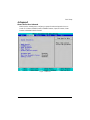
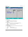
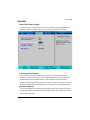
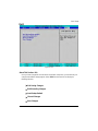
Chapter 3 BIOS Setup ..........................................................................28
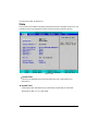
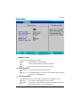
Main...........................................................................................................30
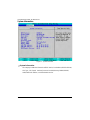
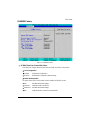
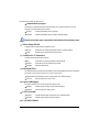
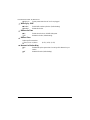
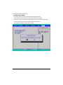
Advanced ...................................................................................................33
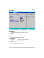
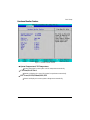
System Information.......................................................................................................... 34
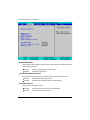
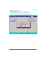
CPU Feature.................................................................................................................... 35
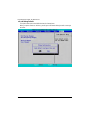
GM965 Feature................................................................................................................ 37
ICH8MDO Feature ........................................................................................................... 39
Super I/O Feature ............................................................................................................ 42
Power Feature ................................................................................................................. 45
Hardware Monitor Feature.............................................................................................. 47

4
GA-6KIEH-RH/GA-6KIEH2-RH/GA-6KIEL-RH Motherboard
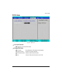
Security ......................................................................................................49
TPM State..................................................................................................51
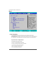
Boot............................................................................................................52
Exit .............................................................................................................53

5
Introduction
The GA-6KIEH-RH motherboard
The GA-6KIEH2-RH motherboard
The GA-6KIEL-RH motherboard
Serial ATA cable x 2
I/O Shield Kit
IDE (ATA100 ) cable x 1
CD for motherboard driver & utility
GA--6KIEH-RH Quick Reference Guide (for GA-6KIEH-RH motherboard)
GA-6KIEH2-RH/GA--6KIEL-RL Quick Reference Guide
(for GA-6KIEH2-RH/GA-6KIEL-RH motherboard)
Item Checklist
* The items listed above are for reference only, and are subject to change without notice.

6
GA-6KIEH-RH/GA-6KIEH2-RH/GA-6KIEL-RH Motherboard
Chapter 1 Introduction
1-1 Considerations Prior to Installation
Preparing Your Computer
The motherboard contains numerous delicate electronic circuits and components which can become
damaged as a result of electrostatic discharge (ESD). Thus, prior to installation, please follow the
instructions below:
1. Please turn off the computer and unplug its power cord.
2. When handling the motherboard, avoid touching any metal leads or connectors.
3. It is best to wear an electrostatic discharge (ESD) cuff when handling electronic components
(CPU, RAM).
4. Prior to installing the electronic components, please have these items on top of an antistatic pad or
within a electrostatic shielding container.
5. Please verify that the power supply is switched off before unplugging the power supply connector
from the motherboard.
Installation Notices
1. Prior to installation, please do not remove the stickers on the motherboard. These stickers are
required for warranty validation.
2. Prior to the installation of the motherboard or any hardware, please first carefully read the
information in the provided manual.
3. Before using the product, please verify that all cables and power connectors are connected.
4. To prevent damage to the motherboard, please do not allow screws to come in contact with the
motherboard circuit or its components.
5. Please make sure there are no leftover screws or metal components placed on the motherboard
or within the computer casing.
6. Please do not place the computer system on an uneven surface.
7. Turning on the computer power during the installation process can lead to damage to system
components as well as physical harm to the user.
8. If you are uncertain about any installation steps or have a problem related to the use of the product,
please consult a certified computer technician.
Instances of Non-Warranty
1. Damage due to natural disaster, accident or human cause.
2. Damage as a result of violating the conditions recommended in the user manual.
3. Damage due to improper installation.
4. Damage due to use of uncertified components.
5. Damage due to use exceeding the permitted parameters.
6. Product determined to be an unofficial Gigabyte product.

7
Introduction
1.2 Features Summary
Form Factor y 170mm x 170mm Mini ITX form factor, 8 layers PCB.
CPU y Supports single Intel
®
Merom/Penryn/Celeron M550 series
processor
(GA-6KIEH-RH) y Socket P with 533/800MHz
CPU y Supports single Intel
®
Celeron M550 series processor
(GA-6KIEL-RH) y Socket P with 533MHz
Chipset y Intel
®
GME965 MCH
(GA-6KIEH-RH) y Intel
®
ICH8M
(GA-6KIEH2-RH)
Chipset y Intel
®
GLE960 MCH
(GA-6KIEL-RH) y Intel
®
ICH8M
Memory y 2 x DDR2 DIMM sockets
y Supports up to 4GB 533/667 memory (GA-6KIEH-RH)
y Supports up to 2GB 533 memory (GA-6KIEL-RH)
y Supports 1.8V DDR2 DIMMs
I/O Control y ITE IT8718F Super I/O
Expansion Slots y Supports 1 PCI slots 32-Bit/33MHz
y Supports 1 mini card slot (PCI-E x1/ USB 2.0)
y Supports 1 mini PCI slot (PCI 33Mhz)
SATA Controller y Built in Silicon Image
®
SiI 3114 with RAID 0,1,10, 5
(GA-6KIEH-RH) y Supports 5 SATA connectors (SiI3114 4 Ports, ICH8M 1 Port)
SATA Controller y Intel
®
ICH8M supports 3 SATA 3.0 Gb/s connectors
(GA-6KIEL-RH)
On-Board Graphic y Intel
®
GMA X3100 3D Graphic Engine (GA-6KIEH-RH)
y Intel
®
GMA X3000 3D Graphic Engine (GA-6KIEL-RH)
y Shared system memory up to 256MB
Internal Connector y 1 x 20-pin ATX power connector
y 5 x SATA connectors
y 1 x IDE connector
y 2 x Serial connectors (COM)
y 1 x front audio connector
y 2 x USB 2.0 connectors for additional 4 ports by cable
y 1 x front panel connecctor
y 1 x System fan cable connector

8
GA-6KIEH-RH/GA-6KIEH2-RH/GA-6KIEL-RH Motherboard
y 1 x CPU fan cable connector
Rear Panel I/O y 1 x SPDIF Out (Coaxial)
y 1 x YPbPr prot (HDTV out )
y 1 x HDMI prot**
y 1 x VGA port
y 1 x DVI-D port**
y 4 x USB 2.0 ports
y 2 x LAN RJ45 ports (GA-6KIEH-RH)
y 1 x LAN RJ45 port (GA-6KIEL-RH)
y 1 HD Audio jacks (Line-out / MIC-in / Line-in) can configure 5.1
channel output by utility
**Note** HDMI & DVI only can select one function to use
**Note** CF device only for Master user, and the IDE Device configuration must set to Slave
Hardware Monitor y Enhanced features with CPU Vcore, 1.5V reference,
VCC3 (3.3V) , VBAT3V, +5VSB, CPUA/B Temperature, and
System Temperature Values viewing
y CPU/Power/System Fan Revolution Detect
y CPU shutdown when overheat
On-Board LAN y Intel
®
82566DC and 82573L GbE controllers (GA-6KIEH-RH)
y Intel
®
82566DC GbE controller (GA-6KIEL-RH)
y Supports WOL, PXE
BIOS y Phoenix BIOS on 8Mb SPI Flash ROM
Additional Features y External Modem wake up
y Supports S1, S3, S4, S5 under Windows Operating System
y Wake on LAN (WOL)
y Supports Console Redirection
y Supports 4-pin Fan controller

9
Introduction
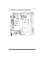
1.3 Motherboard Components (GA-6KIEH-RH)
CPU
Intel
GME965
Intel
82573L GbE
Intel
ICH8M
Silicon
Image
SiI1392
Intel
82566DC
GbE
COM1
COM2
F_AUDIO1
Mini PCI
PCI 32/33MHz
Mini PCI-E
DDRII 1
DDRII 2
ATX Power
F_Panel
Battery
Audio jack
USB
LAN
USB
LAN
VGA
DVI-D
HDMI
SPDIF
YPbPr
Relteak
ALC883
SATA1
SATA2
SATA3
SATA5
SATA4
CPU Fan
SYS Fan
F_USB1
F_USB2
IDE1

10
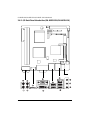
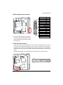
GA-6KIEH-RH/GA-6KIEH2-RH/GA-6KIEL-RH Motherboard
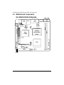
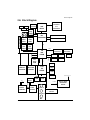
CPU
Intel GME965
(6KIEH2)
Intel GLE960
(6KIEL)
Intel
ICH8M
Silicon
Image
SiI1392
Intel
82566DC
GbE
COM1
COM2
F_AUDIO1
Mini PCI
PCI 32/33MHz
Mini PCI-E
DDRII 1
DDRII 2
ATX Power
F_Panel
Battery
USB
USB
LAN
VGA
DVI-D
HDMI
SPDIF
YPbPr
Relteak
ALC883
SATA1
SATA2
SATA5
CPU Fan
SYS Fan
F_USB1
F_USB2
IDE1
1.4 Motherboard Components
(GA-6KIEH2-RH/GA-6KIEL-RH)

11
Hardware Installation Process
Chapter 2 Hardware Installation Process
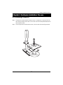
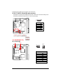
2-1: Installing Processor
Step 1 The processor socket come with a screw to secure the processor. Insert the CPU into
the socket by making sure the notch on the corner of the CPUcorresponds with the notch on
the inside of the socket.
Step 2 Once the processor has slide into the socket, lock the screw. Refer to the figures below.
2
1
Lock
Unlock

12
GA-6KIEH-RH/GA-6KIEH2-RH/GA-6KIEL-RH Motherboard
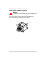
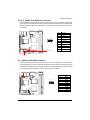
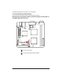
2-2: Installing Processor Colling Fan
!
!
WARNING!
To prevent the CPU overheat, please make sure you have apply the CPU
cooler paste on the surface of installed CPU
Step 1 Attach the heat sink n the procssor socket. Secure the cooing fan with screws.
Step 2 Connect processor fan can cable to the processor fan connector.
1
1
1
2

13
Hardware Installation Process
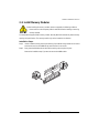
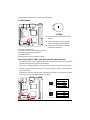
2-3: Install Memory Modules
The motherboard supports DDR2 memory module, whereby BIOS will automatically detect memory
capacity and specifications. The memory module only can be inserted in one direction.
Before installing the memory modules, please comply with the following conditions:
1. Please make sure the computer power is switched off before installing or removing
memory modules.
Installation Steps:
Step 1. Unlock a DIMM socket by pressing the retaining clips outwards. Aling a DIMM on the socket
such that the notch on the DIMM exactly match the notch in the socket.
Step 2. Firmly insert the DIMMinto the socket until the retaining clips snap back in place.
Reverse the installation steps if you want to remove the DIMM module.

14
GA-6KIEH-RH/GA-6KIEH2-RH/GA-6KIEL-RH Motherboard
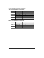
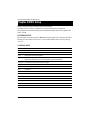
Table 1. Supported DIMM Module Type (GA-6KIEH-RH)
Table 2. Supported DIMM Module Type (GA-6KIEL-RH)
Size Organization RAM Chips/DIMM
256MB 8MB x 8 x 4 bks 8
16MB x 16 x 4bks 16
512MB 16MB x 8 x 4bks 8
32MB x 16 x 4bks 16
1GB 32MB x 8 x 4bks 8
64MB x 16 x 4bks 16
Size Organization RAM Chips/DIMM
256MB 8MB x 8 x 4 bks 8
16MB x 16 x 4bks 16
512MB 16MB x 8 x 4bks 8
32MB x 16 x 4bks 16
1GB 32MB x 8 x 4bks 8
64MB x 16 x 4bks 16
2GB 32MB x 8 x 4bks 8
64MB x 16 x 4bks 16

15
Hardware Installation Process
2-4: Connect ribbon cables, cabinet wires, and power
supply
2-4-1 : I/O Back Panel Introduction (GA-6KIEH-RH)

16
GA-6KIEH-RH/GA-6KIEH2-RH/GA-6KIEL-RH Motherboard
2-4-2 : I/O Back Panel Introduction (GA-6KIEH2-RH/GA-6KIEL-RH)

17
Hardware Installation Process
/ / YPbPr Ports
The "Y," "Pb" and "Pr" are sets of three inputs or outputs on better video equipment and TVs.
Blue port represents Pb port, Red represnts Pr port, and Green represent Y port. Connect the
YPbPr cable to these three ports.
COAXIAL (SPDIF Out)
The SPDIF coaxial output port is capable for providing digital audio to external speakers or
compressed AC3 data to an external Dolby Digital Decoder via a coaxial cable.
HDMI Port
The HDMI (High-Definition Multimedia Interface) provides an all-digital audio/video interface to
transmit the uncompressed audio/video signals and is HDCP compliant. Connect the HDMI
audio/video device to this port. The HDMI Technology can support a maximum resolution of
1920x1080p but the actual resolutions supported depend on the monitor being used.
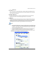
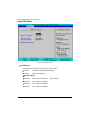
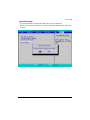
NOTE:
After installing the HDMI device, make sure the default device for sound playback is the
HDMI device. (The item name may differ by operating system. Refer the figures below
for details.), and enter BIOS Setup, then set Onboard VGA output connect to D-SUB/
HDMI under Advanced BIOS Features.
Please note the HDMI audio output only supports AC3, DTS and 2-channel-LPCM
formats. (AC3 and DTS require the use of an external decoder for decoding.)
In Windows XP, select Start>Control Panel>Sounds and Audio Devices>Audio, set the
Default device for sound playback to Realtek HDA HDMI Out.

18
GA-6KIEH-RH/GA-6KIEH2-RH/GA-6KIEL-RH Motherboard
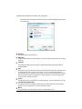
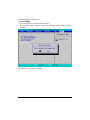
In Windows Vista, select Start>Control Panel>Sound, select Realtek HDMI Output and then
click Set Default.
VGA Port
Connect the monitor cable to this port.
DVI-D Port
The DVI-D port supports DVI-D specifictation. Connect a monitor that supports DVI-D connection
to this port.
LAN Port
The LAN port provides Internet connection of Gigabit Ethernet with data transfer speeds of
10/100/1000Mbps.
USB
Before you connect your device(s) into USB connector(s), please make sure your device(s) such
as USB keyboard, mouse, scanner, zip, speaker...etc. have a standard USB interface.
Also make sure your OS supports USB controller. If your OS does not support USB controller,
please contact OS vendor for possible patch or driver updated. For more information please
contact your OS or device(s) vendors.
Line In
The default Line In jack. Devices like CD-ROM, walkman etc. can be connected to Line In jack.
Line Out (Front Speaker Out)
The default Line Out (Front Speaker Out) jack. Stereo speakers, earphone or front surround
speakers can be connected to Line Out (Front Speaker Out) jack.
MIC In
The default MIC In jack. Microphone must be connected to MIC In jack.

19
Hardware Installation Process
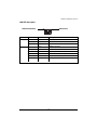
LAN LED Description
LED1 (Green)
LED2 (Green/Yellow)
Color Condition Description
Green ON LAN Link / no Access
Green BLINK LAN Access
- OFF Idle
- OFF 10Mbps connection
- OFF Port identification with 10 Mbps connection
Green ON 100Mbps connection
Green BLINK Port identification with 100Mbps connection
Yellow ON 1Gbps connection
Yellow BLINK Port identification with 1Gbps connection
Name
LED1
LED2

20
GA-6KIEH-RH/GA-6KIEH2-RH/GA-6KIEL-RH Motherboard
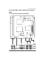
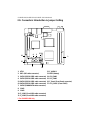
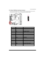
2-5: Connectors Introduction & Jumper Setting
1. ATX1 12. F_AUDIO1
2. IDE1 (IDE cable connector) 13. BAT1 (Battery)
3. SATA1 (SiI3114 SATA cable connector) 14. CPU_FAN1
4. SATA2 (SiI3114 SATA cable connector) 15. SYS_FAN1
5**.SATA3 (SiI3114 SATA cable connector) 16. F_Panel (Front Panel connector)
6**.SATA4 (SiI3114 SATA cable connector) 17. CLR_CMOS (Clear CMOS)
7. SATA5 (ICH8M SATA cable connector)
8. COM1
9. COM2
10. F_USB1 (Fornt USB cable connector)
11. F_USB2 (Fornt USB cable connector)
** For GA-6KIEH-RH Only
1
2
3
4
5
6
7
8
9
10 11
12
13
14
15
16
17
Page is loading ...
Page is loading ...
Page is loading ...
Page is loading ...
Page is loading ...
Page is loading ...
Page is loading ...
Page is loading ...
Page is loading ...
Page is loading ...
Page is loading ...
Page is loading ...
Page is loading ...
Page is loading ...
Page is loading ...
Page is loading ...
Page is loading ...
Page is loading ...
Page is loading ...
Page is loading ...
Page is loading ...
Page is loading ...
Page is loading ...
Page is loading ...
Page is loading ...
Page is loading ...
Page is loading ...
Page is loading ...
Page is loading ...
Page is loading ...
Page is loading ...
Page is loading ...
Page is loading ...
Page is loading ...
Page is loading ...
Page is loading ...
Page is loading ...
Page is loading ...
-
 1
1
-
 2
2
-
 3
3
-
 4
4
-
 5
5
-
 6
6
-
 7
7
-
 8
8
-
 9
9
-
 10
10
-
 11
11
-
 12
12
-
 13
13
-
 14
14
-
 15
15
-
 16
16
-
 17
17
-
 18
18
-
 19
19
-
 20
20
-
 21
21
-
 22
22
-
 23
23
-
 24
24
-
 25
25
-
 26
26
-
 27
27
-
 28
28
-
 29
29
-
 30
30
-
 31
31
-
 32
32
-
 33
33
-
 34
34
-
 35
35
-
 36
36
-
 37
37
-
 38
38
-
 39
39
-
 40
40
-
 41
41
-
 42
42
-
 43
43
-
 44
44
-
 45
45
-
 46
46
-
 47
47
-
 48
48
-
 49
49
-
 50
50
-
 51
51
-
 52
52
-
 53
53
-
 54
54
-
 55
55
-
 56
56
-
 57
57
-
 58
58


Gigabyte GA-6KIEL-RH User manual
- Category
- Motherboards
- Type
- User manual
- This manual is also suitable for
Ask a question and I''ll find the answer in the document
Finding information in a document is now easier with AI
Related papers
-
Gigabyte GA-6KIEH2-RH User manual
-
Gigabyte GA-6JIEV-RH User manual
-
-
-
-
Gigabyte GA-K8NXP-SLI Installation guide
-
-
-
-
Other documents
-
Asus P5G41TM Owner's manual
-
PC CHIPS P23G (V3.0) User guide
-
-
-
OCZ Technology OCZNBIS15DIYA Datasheet
-
 FIC PTBG965EFN LF User manual
-
 Acrosser Technology 486DX2 User manual
-
VIA Technologies VT8237R PLUS Technical Reference Booklet
-
MSI IM-GME965 User manual
-
AMD GA-K8N ULTRA-9 User manual

