Page is loading ...

®
Master Forge & M Design® is a
registered trademark of LF, LLC.
All rights reserved.
WARNING
Improper installation,
adjustment, alteration, service
or maintenance can cause
in)ury or property damage.
Read this instruction manual
thoroughly before·· installing or
servicing this equipment.
WARNING
1. Do not store or use
gasoline or other
flammable vapors and
liquids in the vicinity of this
or any other appliance.
2. An LP tank not connected
for use should not be
stored in the vicinity of this
or an other a Hance.
AoANGER
If you smell gas:
1. Shut off gas to the
appliance.
2.Extinguish any open flames
3. Open the lid.
4. If the odor continues, keep
away from the appliance and
immediately call your gas
supplie~ or fire department.
WARNING
For Outdoor Use Only
ATTACH YOUR RECEIPT HERE
ITEM #0306730
4-BURNER GAS GRILL
MODEL ~GD4833
Espanol p.37
0
--
-----
C
Serial Number. _________ _ Purchase Date· ________ _
Questions, problems, missing parts? Before returning to your retailer, call our
customer service department at 1-800-963-0211, 8 a.m. - 6 p.m., EST, Monday-
Thursday, 8 a.m. - 5 p.m., EST, Friday.
1


TABLE OF CONTENTS
Safety Information·-·· ....
Package Contents
Hardware Contents
Preparation ........... .
Assembly Instructions
Installation Instructions
Operating Instructions
Care and Maintenance
Troubleshooting ......
~~~
.. ..
Exploded View ...
.................................................. 3
················ 5
7
.7
........ 8
................... 19
........... 23
··········27
32
34
Replacement Parts List ........ --. -. -............................ ---. -. -..
· 35
. .. 36
2

A SAFETY INFORMATION
Please read and understand this entire manual before attempting to assemble,
operate or install the product. If you have any questions regarding the product,
please call customer service at 1-800-963-0211, 8 a.m-6 p.m., EST, Monday-
Thursday, 8 a.m.-5 p.m., EST, Friday.
• The installation of this appliance must conform with local codes or, in the absence of local
codes, with the National Fuel Gas Code, ANSI Z 221.3INFPA 54.
• This grill is intended for use outdoors and should not be used in a building, garage or any
other enclosed or covered area.
• This outdoor grill is not intended for installation in or on recreation vehicles and.I or boats.
• A minimum clearance of 36 inches from combustible constructions to the sides of the grill
and 36 inches from the back of the grill to combustible constructions must be maintained.
This outdoor cooking gas appliance must not be placed under overhead combustible
construction.
• The use of an electrical source requires that when installed, the grill must be electrically
grounded in accordance with local codes or, in the absence of local codes, with
ANSl/NFPA 70, or the Canadian Electrical Code, CSAC22.1. Keep electrical supply cords
and the fuel supply hose away from heated surfaces.
• Inspect the hoses before each use for excessive abrasion or wear, or cuts that may affect
safe operation of the grill. lf there is evidence of excessive abrasion or wear, or the hose is
cut, it must be replaced prior to the grill being put into operation. The replacement hose
assembly must be those specified by the manufacturer.
• Keep your grill in an area clear and free from combustible materials, gasoline and other
flammable vapors and liquids.
• DO NOT obstruct the flow of combustion and ventilation air to this appliance.
• Keep the ventilation openings of the tankenclosure free and clear of debris.
• Check all gas connections for leaks with a soapy water solution and brush. Never use an
open flame to check for leaks.
• Never use charcoal in the grill.
• Never use the grill in windy areas.
l
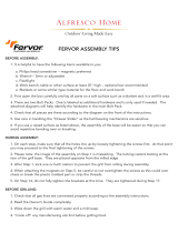
• Only a 20 lb. LP-gas cylinder is allowed. The cylinder must be
constructed and marked in accordance with the Specifications for
18in.
12.2in.
LP Gas Cylinders of the U.S. Department of Transportation (D. 0. T.)
or the National Standard of Canada. CAN/CSA B339. Cylinders.
Spheres and Tubes for Transportation of Dangerous Goods; and
Commission. Dimensions for a 20 lb. LP-Gas cylinder are:
' !
-8in.-
-13.9in. -
• Never use the grill without the drip tray installed and hung under the burner box. Without
the drip tray, hot grease and debris could leak downward and produce a fire hazard.
• Use only the gas pressure regulator supplied with this appliance. This regulator is set for
an outlet pressure of 11.0 we.
• The cylinder used must include a collar to protect the cylinder valve.
3

A SAFETY INFORMATION
• Do not store a spare LP-gas cylinder under or near this appliance.
• Never fill the cylinder beyond 80 percent full.
• Properly route regulator and hose to connect with tank as per the regulator assembly
instructions detailed on page 17 and 18.
• DANGER: If the information in above is not followed exactly, a fire causing death or serious
injury may occur.
• The outdoor cooking gas appliance must be isolated from the gas supply piping system by
closing its individual manual shutoff valve during any pressure testing of the gas supply
system at test pressures equal to or less than 1/2 PSI (3.5 KPa).
• CALIFORNIA PROPOSITION 65 WARNING: The burning of gas cooking fuel generates
some byproducts which are on the list of substances known by the State of California to
cause cancer, reproductive harm, or other birth defects. To reduce exposure to these
substances, always operate this unit according to the use and care manual, ensuring you
provide good ventilation when cooking with gas.
IMPORTANT: We urge you to read this manual carefully and follow the
recommendations enclosed. This will ensure you receive the most enjoyable and
trouble-free operation of your new gas grill. We also advise you retain this manual for
future reference.
WARNING: Your grill has been designed to operate using only the gas specified by the
manufacturer on the rating plate. Do not attempt to operate your grill with other gases.
Failure to follow this warning could lead to a fire hazard and bodily harm and will void
your warranty.
WARNING: Make certain your LP (propane) tank is filled by a reputable propane dealer.
An incorrectly filled or overfilled LP tank can be dangerous. An overfilled tank
combined with the warming of the LP tank (a hot summer day, tank left in the sun, etc.)
can cause LP gas to be released by the pressure relief valve on the tank since the
temperature increase causes the propane to expand. LP gas released from the tank is
flammable and can be explosive. Refer to your Owner's Manual for more information
concerning filling your LP tank.
4

PACKAGE CONTENTS
0
0
-
11
0
'
I '
'
I '
\r
\i,
•t
I
I
'
'
I
~
•s
.,
~-
,
~
0
asmmmmmmmr·
0
-
0
,,
0
/I
I I
I
d
d
I
I
1/
1/
I
I
d
1/
I
G)_
e
0
I
7
.,
G
0
0
•
~ ~
~
~
~ ~
~ ~
~
G
~
~ ~
~
~ ~
~
~
~
~
~ ~
~
~
~
5

PACKAGE CONTENTS
Part
Description
Quantity
A
Firebox and hood
1
assembly
L
Match holder stick
1
B
Warming rack
1
M Drip tray 1
C
Cooking grate
2
N
Door
1
D
Heat tent 4
0 Magnet
1
E Side table (L)
1
p
Gas cylinder safety
1
stop
F
Side table (R) 1
Q
Back panel 1
1
G
Drip tray bracket 2
R Back panel 2
1
H
Left side panel
1
s Bottom panel
1
Right side panel 1
T
Locking caster
2
J
Crossbeam
1
u
Caster
2
K
Door handle 1
V
Grease cup 1
w
Baffle
1
6

HARDWARE CONTENTS
•
•
.
•
•
•
f-"";,.-~
~
.YVJ
;- -- "
ts-~c:;i
,---,_,
,_, __ ,
t~iJ
\:__j
M6 X 12
M6
M4 x8
Screw
Lock Washer
Door Axes Pin
R Pin
Screw
Qty. 21
Qty. 21
Qty. 1
Qty. 2
Qty. 2
•
•
(§}
'
~
'
M6
M3 X 15
M4
ST4.5 x 12
Explosion Proof
Screw
Lock Washer AA Battery
Screw
Washer
Qty. 4
Qty. 2
Qty. 2
Qty. 1
Qty. 4
PREPARATION
Before beginning assembly of product, make sure all parts are present. Compare
parts with package contents list and hardware contents list. If any part is
missing or damaged, do not attempt to assemble the product.
Tools required for assembly (not included): Phillips Screwdriver, Wrench.
7

ASSEMBLY INSTRUCTIONS
1. Install gas cylinder safety stop
Put the gas cylinder safety stop (P) into
the holes of the bottom panel (S), then
turn over the bottom panel (S) and insert
2 R pins (DD) into the small holes of gas
cylinder safety stop (P).
Hardware Used
R Pin
yY) X 2
2. Install casters
Install casters (U) and locking casters
(T) into the holes of the bottom panel
(S) and tighten with a wrench. When
this process is completed, turn over
the bottom panel (S). The two locking
casters (T) should be at the back of
the grill.
8

ASSEMBLY INSTRUCTIONS
3. Install door axes and magnet
Screw door axes pin (CC) into the
assembled holes of the bottom panel
(S) and use M3 x 15 screws (GG) to
install magnet (0).
Hardware Used
•
Door Axes Pin
'
X 1
•
M3 x 15
(])ma
Screws
x2
4. Install left side panel
Install left side panel (H) into bottom
panel (S) with M6 x12 screws (AA)
and lock washers (BB).
Hardware Used
•
A
w
M6 X 12
Screw
M6
Lock Washer
X 3
X 3
0
9

ASSEMBLY INSTRUCTIONS
5. Install right side panel
Install right side panel (I) into bottom
panel (S) with M6 x12 screws (AA)
and lock washers (BB).
Hardware Used
•
A
w
M6 X 12
Screw
M6
~
Lock Washer y
6. Install lower back panel
X 3
X 3
Align the lower back panel (R) to pre-
installed screws on the side panels.
Slide the lower back panel (R) into
place and tighten all 4 screws. Using
an M6 x 12 screw (AA) with an M6 lock
washer (BB), secure middle of the
lower back panel (R) tu the bottom
panel (S).
Hardware Used
•
A
w
M6 X 12
Screw
-:!'-~1~:m-~,\1:
_.,l~,,J;1J:i,:,,
M6 "
Lock Washer y
X 1
X 1
fl I
~i
-
10

ASSEMBLY INSTRUCTIONS
7. Install upper back panel
Align the upper back panel (Q) to pre-
installed screws on side panels. Slide
upper back panel (Q) into place and
tighten all 4 screws. Using an M6 x 12
screw (AA) with an M6 lock washer
(BB). secure middle of upper back panel
(Q) to lower back panel (R).
Hardware Used
•
A
w
M6 X 12
Screw
'
. : >itt'i'.t·'·i'1'
:'l"i"''l·''
,,.(,-:\
1
{,;tl,'J
·U
M6
~
Lock Washer Y
8. Install crossbeam
X 1
X 1
Align holes at either end of
crossbeam (J) to holes in the top
front of side panels. Secure using
M6 x 12 screws (AA) and M6 lock
washers (BB).
Hardware Used
•
A
w
M6 X 12
Screw
M6
~
Lock Washer y
X 4
X 4
11
•·
-
'
:, I 1---,
-
~
~
~ ~
1
1r-""-""-i 1
-
\ \\, '-----'
\\
\
\
\\
\ \\
\\
\
=
=
=
=
=
=
=
=
=
=
=
=
=
=
=
=
=
=
=
=
=
=
=
~
\

ASSEMBLY INSTRUCTIONS
9. Install door handle
Assemble door handle (K) with M4 x
35 screws (EE) and M4 lock
washers (HH) onto the door (N).
Hardware Used
•
M4x 8
··-Tl"'TO
x2
:, Ii:
Screw
;.I.L-t-.i,
CD
M4
g
Lock Washer
x2
1 a. Install door
Align hole in bottom of door (N) to axes
pin at bottom of cart. Locate adjacent
hole in the crossbeam (J) above.
Compress spring loaded pin at top left
of door (N) using finger. Slide door (N)
into place so that the spring pin aligns
with hole. When spring pin releases
into hole, door (N) is installed.
12
·-. I~ -
I~+
I

ASSEMBLY INSTRUCTIONS
11. Install drip tray bracket
Assemble the drip tray brackets (G)
onto both side panels with M6 x 12
screws (AA) and M6 lock washers
(BB).
Hardware Used
•
A
w
M6 X 12
Screw
M6
Lock Washer
12. Install baffle
X 4
X 4
Align holes at either end of baffle (W)
to holes in the top of side panels.
Note: Be sure the legs of baffle (W)
point downward. Then secure using
ST4.5 x 12 screws (JJ).
Hardware Used
•
ST4.5 x 12
Screw
X 4
~
:; (1)
=
-
~~
=
-
=
~
=
-
=
=
=
=
=
=
=
=
=
=
-
-
=
-
-
=
=
•
13

ASSEMBLY INSTRUCTIONS
13. Install firebox and hood assembly
Set firebox and hood assembly (A) onto
cart. Align the 4 pre-drilled holes in
bottom of firebox and hood assembly
(A) to the pre-drilled holes in the top of
the cart assembly. Using 4 M6 x 12
screws (AA), 4 M6 lock washers (BB),
and 4 M6 explosion proof washers (FF)
secure firebox and hood assembly (A)
to cart.
Hardware Used
•
M6 X 12
Screw
!r,1·'Y'"1''·~
d, 1,.1,1 II,'
, • I.I.,] I,, ·:1
X 4
' ' ,,, "'
' : ,,,i,"-lvc.Y>
•
M6
g
Lock Washer
X 4
-
•
M6 @y
Explosion Proof CJ
X 4
Washer
14. Install both side tables (left and right)
Install left and right side tables(E and
F). Align side table with the pre-
installed screws of firebox and hood
assembly (A), then tighten the screws
with screw driver.
14
0
0
-
•
•

ASSEMBLY INSTRUCTIONS
15. Check the distance between the
ignition pin and the burner ports
If the distance between the ignition pin and
the burner ports is not the same as
illustrated, loosen the ignition pin screws,
adjust the distance and then re-tighten the
screws.
EB;i1; g .... 1
;'; I
l"'.:IJ!LJd:M I
Main
Burner
16. Install heat tents
Insert heat tents (D) over each burner
inside the firebox and hood assembly
(A). Direct the tabbed end of heat tent
(D) toward front of grill. Observing slots
in front of firebox and hood assembly
(A) that align with tabs on heat tent (D).
Insert tabs into slots in firebox and
hood assembly (A). Allow back side of
heat tent (D) to rest on the V-shaped
support mounted on the back side of
the firebox and hood assembly (A).
• ••• .-----:~----;;:::=---------
1
17.lnstall warming rack and assemble
cooking grate
Place cooking grate (C) and warming rack
(B) onto firebox and hood assembly (A).
15

ASSEMBLY INSTRUCTIONS
18. Install grease tray and grease cup
Slide grease cup (V) into brackets on
bottom side of drip tray (M). Slide drip
tray (M) into brackets underneath firebo
and hood assembly (A).
19.lnstall match holder
a. Locate hole at the top front of the
right side panel of the cart. Using an
M6 x12 screw (AA) and an M6 lock
washer (BB). secure the chain to the
side of the cart. Hang the match holder
from the hook just below the side
table.
b. Install AA battery (II) into the
igniter assembly by unscrewing the
housing for the igniter button. Insert
battery (II) negative end first into
igniter assembly. Place the igniter
button back over the battery (II) and
hand tighten. Press igniter to test. If
igniter is not working please refer to
the Troubleshooting section.
Hardware Used
•
A
w
M6 x 12
Screw
M6
~
Lock Washer y
X 1
X 1
-
~
0
-
16

ASSEMBLY INSTRUCTIONS
20. Connect regulator with gas tank
a. Untie regulator and hose
Untie the regulator and hose under from
the control panel on the firebox and hood
assembly (A). Remove the bubble bag
from the regulator. After untying, the
regulator and hose should hang down
outside the cart.
b. Route regulator and hose
The regulator and hose assembly must
be routed through the hole of the left
side panel (H) into the cart.
0
-
Cl
0
17

ASSEMBLY INSTRUCTIONS
c. Install gas tank
Place 20 lb. LP tank (not included) into
round opening in the bottom of cart. Secure
tank using gas cylinder safety stop (P).
Connect regulator to tank and tighten
by hand. Your grill is now ready for use.
0
-
INCORRECT REGULATOR ASSEMBLY
The regulator and hose should not be routed through the gap between the bottom
of firebox and the top of cart. Incorrect assembly will result in loss of warranty.
Incorrect assembly may cause gas leakage, fire and severe bodily harm. The
regulator and hose assembly must be routed through the hole of the left side
panel into the cart.
CHECK FOR SPARKS
After grill assembly is completed, test the ignition system with the GAS OFF.
Check for sparks when using the ignition system.
Be sure the GAS IS OFF when you push the electrical igniter. This will help assure a
trouble-free ignition when you turn on the gas.
18

INSTALLATION INSTRUCTIONS
For Portable LP-Gas Connection
The cabinet has an opening in the bottom panel that allows a 20 lb. gas tank bottom flange
to drop into place (tank not included). This will help to lock the tank in place. After positioning
the tank in the opening. lift up the gas cylinder safety stop to lock the tank (Fig. 21 ).
Use only 20 lb. gas tank (See LP Gas Safety Requirements for additional information).
As shown in Fig. 22, it is unsafe to operate the grill if the gas tank is not vertical.
0
0
- -
.
,e
e•e
El);
.
-/
'
~
,_,
~
-
1J
=
Fig. 21
Fig.22
WARNING:The Type I connective coupling(see Fig. 23)supplied with your grill must
not be replaced with a different type of grill/tank connection system. Removal will
result in loss of warranty, gas leakage, fire and severe bodily harm.
Thermally
Sensitive Nut
Hand Wheel External /
\
Thread Propane
(
. _j--I._ ./ Regulator
lfv: I -----------
~
: - _/
~~I~
--------'O~>c:~:=:jj
~
c-=i'
~
---- l_
-·-·
Fig. 23
The propane tank valve connection supplied with this grill incorporates four important safe
guards: Hand Assembly, Hand Disassembly, Excess Flow Control and Temperature-Activated
Shut-Off.
a. Hand Assembly:
1. Make certain the tank valve and all the appliance valves are in the "OFF" position.
19
/