Page is loading ...

OWNER’S AND OPERATOR’S MANUAL
Vertical, Water-Cooled 4-Cycle Diesel Engine
DGW420DM/ANZ
X750-022 87 0
X750803-640 0
CAUTION
Do not operate the Generator/Welder, or any other appliance, before you have
read and understood the instructions for use and keep near for ready use.


Introduction
We would like to thank you very much for purchasing this Shindaiwa Soundproof
Diesel Engine Generator & Welder.
•
This manual has been created in order to ensure safe and proper use of this
equipment. Be sure to thoroughly read this manual before operating the equipment
as the improper operation of this equipment can result in an accident or
malfunction.
•
This equipment should only be operated by persons who thoroughly understand the
contents of this manual and can safely operate the equipment. Persons who are ill,
taking medicine, or are in bad health should not operate this equipment if such
conditions will affect operation of the equipment and related work.
•
Operation and use of this equipment must be in strict compliance with the
applicable laws, as well as rules and regulations based on such laws.
•
Always be sure to include this manual with the equipment if it is loaned out to
another party, and instruct said party that they must thoroughly read this manual
before operating the equipment.
•
Store this manual securely in a predetermined location so that it can be readily
accessed at all times to order parts or arrange for repair. Contact the retail outlet
where this equipment was purchased if any parts are lost, the equipment becomes
soiled, or is otherwise damaged in any manner.
•
Consult with the retail outlet where the equipment was purchased if any of the
points are unclear or you would like further information.
Be sure to note the model name and serial number of your equipment, and provide
this information when making an inquiry.
•
If disposing of this equipment, dispose in a manner according to laws and
regulations applicable to industrial waste. Consult with the retail outlet where the
equipment was purchased if you have any inquiries regarding proper disposal.
The precautions used in this manual are divided into the following three ranks.
•
It is possible that items described under < Caution > or < Note > can result in a
serious accident depending on the circumstances. The contents of both of these
types of precautions are important. Be sure to always comply with all precautions.
Warning: Improper operation can result in death or serious personal injury.
Caution: Improper operation can result in moderate or minor personal injury, or
physical damage.
<Note>: Explanatory note in order to ensure that equipment protection and
performance are fully realized.

- 1 -
Table of Contents
1. Safety Precautions ............................................................................... 2
2. Specifications ....................................................................................... 6
3. Applications .......................................................................................... 6
4. Part Names............................................................................................ 7
5. Equipment ............................................................................................. 9
5-1. Spill Containment........................................................................... 9
5-2. VRD (Voltage Reduction Device).................................................. 9
5-3. Idle Control .................................................................................... 9
5-4. Weld Output Control .................................................................... 10
5-5. Wire Feeder Control .................................................................... 11
5-6. Remote Control (9-Pin Connector).............................................. 12
5-7. Meter............................................................................................ 12
5-8. Error Code Display ...................................................................... 12
5-9. Monitor Lamp............................................................................... 13
5-10. Earth Leakage Circuit Breaker and Grounding......................... 14
5-11. Emergency Stop Switch............................................................. 15
5-12. Battery Isolator .......................................................................... 15
5-13. Operation Mode Selector .......................................................... 15
6. Pre-Operation Inspection................................................................... 16
6-1. Engine Oil Inspection .................................................................. 16
6-2. Cooling Water Inspection ............................................................ 17
6-3. Fuel Inspection ............................................................................ 17
6-4. Spill Containment Inspection....................................................... 18
6-5. Inspection for Fuel/Oil/Cooling Water Leakage .......................... 18
6-6. Battery Inspection........................................................................ 18
7. Operating Procedures........................................................................ 19
7-1. Starting the Engine ...................................................................... 20
7-2. Stopping the Engine .................................................................... 21
7-3. Emergency Stop .......................................................................... 21
8. Using as a Welder............................................................................... 21
8-1. Welding Cable Selection ............................................................. 21
8-2. Welding Polarity........................................................................... 22
8-3. Welding Cable Connection.......................................................... 22
8-4. Duty Cycle ................................................................................... 23
8-5. Welding Work .............................................................................. 23
9. Using as a Generator ......................................................................... 26
9-1. Output Types and Ranges........................................................... 26
9-2. Usable Device Capacities ........................................................... 26
9-3. Operation..................................................................................... 27
10. Simultaneously Welding and Using as AC Power Source........... 28
11. Inspection/Maintenance................................................................... 29
12. Long-Term Storage........................................................................... 35
13. Troubleshooting ............................................................................... 36
14. Engine Wiring Diagram .................................................................... 39
15. Generator Wiring Diagram............................................................... 40

- 2 -
1. Safety Precautions
Warning: Suffocation from Exhaust Fume
•
Do not operate the equipment in a poorly-ventilated area such as indoors or within a
tunnel because the engine exhaust fume includes components that are harmful to
humans.
Warning: Suffocation from Welding Fume
•
Always be sure to wear a fume-proof mask when welding as the fumes generated
during welding include harmful gases and dust. Also be careful that the wind direction
is not such that it will cause fumes to be inhaled and always operate the equipment in
a well-ventilated area.
Warning: Electric Shock
•
Do not operate the equipment with any doors or covers open.
•
Do not touch wirings or any electric parts inside the equipment during operation.
•
Do not touch the equipment during operation if the equipment or your body is wet.
•
Be sure to stop the engine whenever touching Weld output terminals such as when
installing or removing welding cables.
•
Do not connect welding cables to any part other than Weld output terminals.
•
Do not insert any metallic objects, such as pins or wires, into AC output receptacles
or remote control
ler
connectors.
•
Always be sure to turn off all breakers before installing or removing devices using AC
output receptacles.
•
Always be sure to repair the corresponding earth leakage location when earth
leakage circuit breakers operate.
•
Always be sure to stop the engine and remove the starter key before performing any
equipment check or maintenance.
Warning: Fire
•
Always be sure to stop the engine when inspecting fuel or refueling, and absolutely
never perform such tasks near fire or other open flame. Wait until the engine has
completely cooled before inspecting fuel or refueling.
•
Always be sure to wipe up any spilled fuel or oil.
•
Spilled fuel and oil accumulates in the spill containment. Do not operate the
equipment with liquid accumulated in the spill containment.
•
Absolutely never use the equipment if there is a fuel, oil or cooling water leak, and be
sure to always repair the leak before using.
•
Absolutely never inspect or perform maintenance to the equipment near fire or other
open flame.
•
Keep any ignitable items (such as fuel, gas and paint) or inflammable items away
from the equipment because the muffler, exhaust fume and other parts attain high
temperatures.
•
Keep any ignitable items (such as fuel, gas and paint) or inflammable items away
from the work area due to the scattering of weld spatter that occurs during welding.
•
Provide at least 1 meter (3 feet) of distance between the equipment and walls and
other obstacles, and operate the equipment on a flat surface.
•
Allow the equipment to cool before covering with protective covers and similar items.
•
Do not ground wiring of earth leakage circuit breakers of the equipment to piping that
passes through flammable material.

- 3 -
Warning: Injury
•
Do not operate the equipment with any doors or covers open. There is a danger of
hair, body parts and other items being caught up in moving parts such as cooling fans
and belts.
•
Do not modify the equipment and do not operate with parts removed.
•
Always be sure to stop the engine and remove the starter key before performing any
equipment check or maintenance.
Warning: Injury to Eyes and Skin
•
Use protective gear, such as rubber gloves, when inspecting or replacing the battery
due to the dilute sulfuric acid in the battery fluid. Be sure that fluid does not get into
eyes, or on skin or clothing.
•
If battery fluid gets into the eyes, or on the skin or clothing, immediately wash with a
large amount of water, and always be especially sure to seek medical attention if it
gets into the eyes.
Warning: Explosion
•
Do not operate the equipment or recharge the battery when the battery fluid level is
below the lower level.
•
Do not generate any sparks near the battery and do not allow any fire or other open
flame near the equipment because the battery generates ignitable gas.
Warning: Electromagnetic Interference
•
Persons using a heart pacemaker are not allowed near the welder or welding work
area while welding is being performed without the permission of a doctor. The welder
generates a magnetic field while energized that can negatively affect pacemaker
operation.
Caution: Suffocation from Exhaust Fume
•
Do not direct the engine exhaust towards passersby, private homes or similar
persons/locations because the engine exhaust fume includes components that are
harmful to humans.
Caution: Electric Shock
•
Do not sprinkle water on the equipment and do not use where exposed to rain.
•
If wearing gloves, be sure to always wear gloves with dry insulation properties. Do
not wear gloves that are damaged or wet.
Caution: Burn
•
The engine, muffler and similar parts are extremely hot during operation and
immediately after stopping the equipment. Never touch hot parts.
•
Never open the radiator cap during operation or immediately after stopping the
equipment. Hot cooling water and steam will spurt out.
•
Always be sure to stop the engine and allow it to cool before inspecting or changing
the engine oil. Opening the oil gauge or oil plug during operation will result in hot oil
spurting out.

- 4 -
Caution: Injury
•
Use this equipment with it situated on a stable level surface so that it is prevented
from moving.
•
Do not move the equipment during operation.
•
Always be sure to turn off the switches of all devices using the equipment and turn off
the equipment breakers before starting the engine.
•
Always be sure to turn off the power switches of all devices using the equipment
when turning on the equipment breakers. Leaving on the power switch of a device
using the equipment when the equipment breakers are turned on could result in the
sudden operation of the corresponding device.
•
Do not leave on the power switch of a device using the equipment and do not
connect a device to an AC output receptacle.
•
The lifting lug is designed to be used only for lifting the equipment. Do not lift the
equipment with any heavy items (such as a trailer, gas canister and additional fuel
tank) added to the equipment.
•
Always be sure to use the lifting lug when lifting the equipment, and lift slowly and
directly straight above.
•
Wear a helmet, safety shoes, gloves and similar protective gear when performing
lifting work. Do not stand or get under the equipment while it is suspended.
•
Securely fix the equipment with rope or similar item so that it cannot move when
transporting by truck or other vehicle.
Caution: Injury to Eyes and Skin
•
Always be sure to wear arc-proof glasses, clothes that completely cover the skin and
other protective gear when welding to protect the eyes and skin from harmful light
rays generated during welding.
•
Always be sure to wear leather gloves, apron, shoe covers, arc-proof glasses (face
shield), safety shoes, hard hat and long-sleeve clothing to protect against the
scattering of weld spatter that occurs during welding.
Caution: Physical and Secondary Damage
•
Do not use the equipment for any improper applications. Improper usage can result in
an accident or malfunction.
•
Do not connect the AC power source to indoor wiring.
•
If using the equipment as a power source for medical equipment, you must check
with the medical equipment manufacturer, doctor and hospital before using the
equipment.

- 5 -
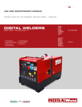
Location of Warning Labels
Replace warning labels when they become difficult to see or damaged by affixing
new labels in the specified locations. Order the necessary labels by numbers in
parentheses.
(1) Suffocation from Exhaust Fume (No. X505-007590)
(2) Suffocation from Welding Fume (No. X505-007600)
(3) Electric Shock (No. X505-007610)
(4) Injury (No. X505-007630)
(5) Burn (No. X505-007620)
(6) Fire (No. X505-007650)
(7) Injury (No. X505-007550)
(8) Burns (No. X505-007660)
(5)
(4)
(8)
(7)
(6)
(1)
(2)
(3)

- 6 -
2. Specifications
Model DGW420DM
Generating Method Rotating Field
Operation Single Dual
Rated Current (A) 390 200
Rated Voltage (V) 35.6 28.0
Duty Cycle (%) 60 100
Current Adj. Range (A) 95 – 400 50 – 210
Welding Rod (φ)
2.6 – 8.0 2.0 – 4.0
CC
DROOP
Gouging Rod (φ)
3.2 – 8.0 3.2 – 5.0
Rated Current (A) 350 200
Rated Voltage (V) 32.5 21.0
Duty Cycle (%) 100 100
Voltage Adj. Range (V) 14 – 35 14 – 23.5
CV
Welding Wire (φ)
0.6 – 2.0 0.6 – 1.6
Rated Speed (min
-1
) 3000
Welding Generator
No Load Voltage (V) MAX 85
Rated Frequency (Hz) 50
Rated Speed (min
-1
) 3000
Phase 1 Phase 3 Phase
Rated Voltage (V) 240 415
Power Factor 1.0 0.8
Rated Output (kVA) 10.8 14.0
AC Generator
Rating Continuous
Model Kubota D1105
Type Vertical, Water-Cooled 4-Cycle Diesel Engine
Displacement (L) 1.123
Rated Output (kW/min
-1
) 18.5 / 3000 (Gross Intermittent)
Fuel ASTM No.2-D Diesel Fuel or Equivalent
Lubricant Oil API Class CD or better
Lubrication Oil Volume (L) 5.1 (Effective 1.4)
Cooling Water Volume (L) 4.3 (Sub Tank Capacity 0.6 L included)
Engine
Starting Method Starter Motor
Battery 55B24L (Japanese Industrial Standard)
Fuel Tank Capacity (L) 43
Length (mm) 1435
Width (mm) 700
Dimen-
sion
Height (mm) 848
Dry Weight (kg) 480
3. Applications
Shielded Metal Arc Welding
Semi-automatic Arc Welding (MIG, MAG, Self-Shielded)
Gouging
Scratch Start TIG
Power Source for Light, Electric Tools and Appliances
Caution: Physical and Secondary Damage
•
Do not use the equipment for any applications not listed above. Improper usage can
result in an accident or malfunction.
•
If using the equipment as a power source for medical equipment, you must check
with the medical equipment manufacturer, doctor and hospital before using the
equipment.

- 7 -
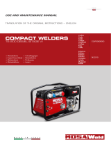
4. Part Names
Weld Terminals
A
Weld Terminals
B
Operation Panel
Terminal Cover
9
-
Pin Connector
14
-
Pin Connector
Circuit Protector
for Wire Feeder
Hour Met
er
Fuel Meter
Monitor Lamp
Starter Switch
Idle Control Switch
Weld Terminal
Switch
Wire Feeder
Voltmeter Selector
42V/115V Selector
VRD Switch
AC Meter
DC Meter
Output Control
Dial
ECO Drive Display
VRD Lamp
Single/Dual
Selector
Weld Mode
Selector
Arc Control
Dial
AC Meter
Selector
Operation
Mode
Selector
Emergency
Stop
Switch
3
-
P Receptacle
1
-
P Receptacle
Main Breaker
Earth Leakage Circuit
Breaker (ELCB)
3
-
P Breaker
1
-
P Breaker
Bonnet Grounding
Terminal
Forklift Skid

- 8 -
Engine
Warranty
Owner’s and
Operator’s
Manual
Door Key
1 Set
Accessories
Operation Mode
Selector Key
1 Set
Engine Key
1 Set
Tail Pipe
1 part
Pipe Band
1 part
Terminal Cap
(Black/For [
-
])
2 parts
Terminal Cap
(Red/For [ + ])
2 parts
Air Cleaner
Oil Plug
Oil Inlet
Sub Tank
Oil Filter
Right Door
Fuse
(50A,20A)
Oil Gauge
Battery Isolator
Battery
Fuel Lever
(Fuel Strainer)
Water Drain Plug
Oil Drain Plug
Fuel Drain Plug
Spill Conta
inment Drain
Spill Containment
Fuel Inlet Cover
Fuel Inlet
Lifting Lug
Muffler
(Tail Pipe)
Top Plate

- 9 -
5. Equipment
5-1. Spill Containment
Warning: Fire
•
Always be sure to wipe up any spilled fuel or oil.
•
Spilled fuel and oil accumulates in the spill containment. Do not operate the
equipment with liquid accumulated in the spill containment.
•
Absolutely never use the equipment if there is a fuel, oil or cooling water leak, and
be sure to always repair the leak before using.
The equipment includes a spill containment (structure that collects leaking liquid) in
order to prevent leaking liquid from getting outside of the equipment if oil, fuel or other
liquid should leak. Before starting operation, check if there is any fluid accumulated in
the spill containment and drain any accumulated liquid. (Refer to section "11.(7)
Draining Liquid from the Spill Containment".)
<Note>
•
It is necessary to periodically drain the liquid from within the equipment because any
rainwater that leaks into the equipment also accumulates in the spill containment.
•
Although the fluids that can leak internally consist of oil, fuel and cooling water, the
spill containment does not have a function that can separate rainwater that has leaked
into the equipment from these internally leaked fluids. Properly dispose of liquid
drained from the spill containment in a manner according to the applicable laws and
regulations.
5-2. VRD (Voltage Reduction Device)
The equipment includes a voltage reduction device
on the weld output side. The voltage reduction
device reduces the output voltage of the welder
when welding is paused in order to further increase
safety when welding in locations with high humidity,
elevated locations, extremely confined spaces near
possible hazards, and similar conditions.
When not welding, the voltage reduction device reduces the voltage of the Weld output
terminals to 35 V or less.
When welding is started, the voltage-reduction function is cancelled and the equipment
returns to the reduced voltage status when welding is completed. Turning the VRD
switch to "TEST" also cancels the voltage-reduction function.
The green VRD lamp ("BELOW 35V" side) lights up when weld output voltage is less
than 35 V and the red lamp ("AT OR ABOVE 35V" side) lights up when the voltage is
35 V or more.
<Note>
•
The VRD is only for weld output. It does not function for AC generated output voltage.
5-3. Idle Control
The equipment includes an idle control function.
You can use the idle control switch to select an
engine speed setting of "ECO", "AUTO" or "HIGH".
(1) ECO Drive
The equipment includes an eco drive function in
order to reduce noise, save fuel, and reduce
exhaust gas emission.
When the idle control switch is set to "ECO" and only welding is being performed, the
engine operates at an optimal speed corresponding to the weld output and it
automatically returns to low speed when welding is stopped.
The eco drive display lights up during eco drive to indicate that operation is
environmentally considerate.
VRD Switch
VRD Lamp
Idle Control
Switch

- 10 -
<Note>
•
The engine speed optimization function of eco drive is only for
"DROOP" and "CC" welding. (It does not function if "CV-WIRE"
is selected using the weld mode selector.)
•
If using as an AC power source during eco drive (including
when welding and using as an AC power source at the same
time), the engine operates at high speed and the eco drive
display turns off.
•
Set the idle control switch to "AUTO" or "HIGH" if welding or using as an AC power
source in an intermittent manner.
•
Set the idle control switch to "HIGH" if using a high capacity motor, precision
instruments or AC load with an attached magnetic switch.
•
Set the idle control switch to "HIGH" if using as an AC power source of a device of
0.5A or less because the engine might not reach a high speed as speed control does
not operate at that level.
(2) Auto Idle
The equipment includes an auto idle function in order to reduce noise, save fuel, and
reduce exhaust gas emission.
You can set the idle control switch to "AUTO" so that the engine operates at low speed
when not welding or using the equipment as a power source.
When you start to weld or use as an AC power source, the engine automatically
increases to high speed. When in a no-load condition, the engine automatically returns
to low speed after approximately 8 seconds of high-speed operation.
<Note>
•
Set the idle control switch to "HIGH" if using a high capacity motor, precision
instruments or AC load with an attached magnetic switch.
•
Set the idle control switch to "HIGH" if using as an AC power source of a device of
0.5A or less because the engine might not reach a high speed as speed control does
not operate at that level.
(3) High Idle
You can set the idle control switch to "HIGH" to maintain the engine constantly at high
speed.
5-4. Weld Output Control
(1) Weld Mode Selector
You can select a weld mode of "CV",
"DROOP" or "CC" in accordance with the
type of welding being performed.
CV (Constant Voltage)
You can use the equipment as a power
source for semi-automatic arc welding
(MIG, MAG and self-shielded).
DROOP (Drooping Characteristic)
The weld current can be adjusted by manipulating the welding rod due to being
able to increase or decrease the current for changing the arc length, thereby
allowing you to adjust the arc status and weld beads.
The arc start is good and the arc is strongly felt.
This mode is optimal for welding work such as pipe welding or when using special
welding rods.
CC (Constant Current)
Welding can be performed at a constant uniform current even if the arc length
changes due to a shaky hand or similar cause to provide a stable arc that is not
easily extinguished.
Welding can be performed at a specified current value without being affected by
the length or thickness (thinness) of the welding cable.
This mode is optimal for general welding as the stable arc reduces the amount of
spatter.
ECO Drive Display
Arc Control
Dial
Output Control
Dial
Weld Mode
Selector

- 11 -
(2) Weld Output Pre-Set
The equipment includes a weld output pre-set function.
If the weld mode selector is set to "CV", you can pre-set the output voltage using the
output control dial.
If the weld mode selector is set to "DROOP" or "CC", you can pre-set the output
current using the output control dial.
(3) Arc Control (for CC mode)
The equipment includes an arc control function that adjusts
the arc strength.
You can adjust the setting of the short-circuit current of the
weld output by turning the arc control dial.
<Note>
•
The arc control function is only for "CC" mode. It does not
function if using "CV" or "DROOP".
•
Always turn the arc control dial to "0"(zero) when the scratch start TIG welding is
functioned otherwise a welding current becomes unstable as the arc control is
functioned.
5-5. Wire Feeder Control
A wire feeder with a 14-pin plug can be used
with this equipment.
(1) 14-Pin Connector
Connecting the 14-pin plug of a wire feeder to
the 14-pin connector of the equipment allows
you to adjust the output voltage by using the
wire feeder.
(2) Weld Terminal Switch
Voltage is constantly output from the
equipment weld terminals when the weld
terminal switch is set to "WELD TERMINALS
ON".
When the weld terminal switch is set to
"REMOTE CONTROL", voltage is output from
the equipment weld terminals only when the
torch switch is set to "ON".
(3) Wire Feeder Voltmeter Selector
By switching the wire feeder voltmeter selector,
you can select the polarity of the voltmeter
display equipped to the wire feeder.
(4) 42V/115V Selector
You can switch the 42V/115V selector to select
the voltage supplied to the wire feeder.
(5) Circuit Protector for Wire Feeder
The circuit protector for the wire feeder operates to stop the current if the there is an
overcurrent of 5A or more in the wire feeder.
<Note>
•
The wire feeder control function is only for output A.
•
When the circuit protector for the wire feeder operates due to an overcurrent fault,
inspect for the fault and press the circuit protector button after resolving the fault in
order to reset the system.
Arc Control Dial
Weaker
Stronger
14-Pin
Connector
Wire Feeder
42V/115V
Selector
Circuit Protector
for Wire Feeder
Wire Feeder
Voltmeter Selector
Weld Terminal
Switch
14-Pin Connector

- 12 -
5-6. Remote Control (9-Pin Connector)
You can connect a compatible remote controller to
the 9-pin connector to enable remote operation of
weld output adjustment.
<Note>
•
The output control dial for the remote control
connection side of the equipment does not
function when a remote controller is connected.
•
If the remote controller is removed from the
remote controller receptacle while welding, the
equipment output control dial becomes
functional, possibly resulting in a sudden
increase or decrease in weld output.
5-7. Meter
The equipment includes a DC meter that provides digital display of both weld current
and voltage, and an AC meter that provides digital display of voltage, current and
frequency of three phase generated output.
(1) DC Ammeter – Voltmeter
The DC ammeter and voltmeter display the weld
output for both outputs A and B separately.
If the single/dual selector is set to "SINGLE", the DC
meter for output B does not display current or
voltage.
<Note>
•
If the weld mode selector is set to "CV", the set
voltage that has been pre-set using the output
control dial is displayed by the voltmeter when not
welding. (The DC ammeter display is blank when
not welding.)
•
If the weld mode selector is set to "DROOP" or "CC", the set current that has been
pre-set using the output control dial is displayed by the DC ammeter when not welding.
(The voltmeter display is blank when not welding.)
•
During welding, both the DC ammeter and voltmeter display the actual output values.
When welding is completed, both meters display the actual output values for
approximately 8 seconds, after which display returns to the pre-set values.
(2) AC Meter
The equipment includes an AC meter that displays
the three phase generated output.
The AC meter is equipped with an AC meter selector
that can be switched to display three phase voltage,
three phase current or frequency.
<Note>
•
During operation, the three phase output voltage of
the AC power source is constantly displayed
regardless of whether the breaker for three phase
voltage is set to "ON" or "OFF".
5-8. Error Code Display
The equipment includes an error code
display function that notifies the operator
of any errors during operation. If an error
is detected during operation, error codes
are displayed by the DC and AC meters.
If this occurs, stop operation immediately,
and inspect and repair the location
where the error has occurred.
(Refer to section "13. Troubleshooting".)
9-Pin Connector
Remote Controller
(Compatible)
DC Meter
Single/Dual Selector
AC Meter
AC Meter Selector
Error Code Display
(Also used as DC and AC meters)

- 13 -
5-9. Monitor Lamp
Warning: Injury/Electric Shock
•
Do not operate the equipment with any doors or covers open. There is a danger of
hair, body parts and other items being caught up in moving parts such as cooling
fans and belts.
Caution: Burn
•
The engine, muffler and similar parts are extremely hot during operation and
immediately after stopping the equipment. Never touch hot parts.
•
Never open the radiator cap during operation or immediately after stopping the
equipment. Hot cooling water and steam will spurt out.
•
Always be sure to stop the engine and allow it to cool before inspecting or changing
the engine oil. Opening the oil gauge or oil plug during operation will result in hot oil
spurting out.
The equipment includes monitor lamps for water
temperature, battery charge, oil pressure and spill
containment.
If the equipment is normal, the "CHARGE" and "OIL
PRESS" monitor lamps light up when the starter switch
is switched from "STOP" to "RUN", and all monitor
lamps turn off when the engine is started. If any error
besides that of spill containment occurs during
operation, the corresponding monitor lamp lights up
and the engine is automatically stopped. If the engine
is automatically stopped, return the starter switch to
"STOP" and restart the engine. Watch the lit/unlit status
of the monitor lamps the next time an automatic stop
occurs and check the error contents.
(1) Water Temperature Monitor Lamp
The water temperature monitor lamp ("WATER TEMP") lights up and the engine is
automatically stopped if the cooling water temperature becomes irregularly high during
operation. If this occurs, inspect the water level of the sub tank and add cooling water if
the water level is insufficient. (Refer to section "6.2 Cooling Water Inspection".)
If the cooling water in the sub tank is at the specified level, it is probable that
overloading is the cause. Use within the rated output.
(2) Battery Charge Monitor Lamp
The battery charge monitor lamp ("CHARGE") lights up and the engine is automatically
stopped if battery charge fails during operation. If this occurs, it is probable that there is
fan belt damage or a wiring fault. Request repair at the retail outlet where the
equipment was purchased.
(3) Oil Pressure Monitor Lamp
The oil pressure monitor lamp ("OIL PRESS") lights up and the engine is automatically
stopped if the engine oil pressure drops during operation. If this occurs, inspect the
engine oil level and fill with engine oil until it reaches the maximum level.
<Note>
•
The oil pressure monitor cannot detect oil deterioration. Change the engine oil
periodically. (Refer to section "11. Inspection/Maintenance".)
•
The charge monitor cannot detect battery deterioration or insufficient battery fluid.
Inspect the battery fluid level periodically. (Refer to section "6-6. Battery Inspection".)
•
Inspect the fuses if the engine is automatically stopped and none of the monitor lamps
("WATER TEMP", "CHARGE" and "OIL PRESS") light up. (Refer to section "4. Part
Names" for fuse location.)
If a fuse has blown, it is probable that there is a fault in an electric part or the wiring.
Request repair at the retail outlet where the equipment was purchased.
Battery
Charge
Water Temp
Oil Press
Spill
Containment

- 14 -
(4) Spill Containment Monitor Lamp
The spill containment monitor lamp ("SPILL CONTAINMENT") lights up if the level of
liquid in the spill containment is approximately 70% full (approx. 43 L) in order to
ensure that liquid accumulated in the spill containment does not spill out of the
equipment. If this occurs, drain the accumulated liquid from the equipment. (Refer to
section "11.(7) Draining Liquid from the Spill Containment".)
<Note>
•
The engine is not stopped if the spill containment monitor lamp lights up during
operation.
•
When the spill containment monitor lamp lights up during operation, stop the engine,
check for fuel, oil and cooling water leakage, and repair as necessary.
•
Do not use the equipment with liquid accumulated in the spill containment. Drain the
spill containment before using. (Refer to section "11.(7) Draining Liquid from the Spill
Containment".)
5-10. Earth Leakage Circuit Breaker and Grounding
Warning: Electric Shock
•
Always be sure to repair the corresponding earth leakage location when earth
leakage circuit breakers operate.
Warning: Fire
•
Do not ground wiring of earth leakage circuit breakers of the equipment to piping
that passes through flammable material.
The equipment includes earth leakage circuit breakers (solidly grounded type) in order
to prevent electric shock. Immediately isolate the electrical circuit if earth leakage
occurs due to insulation failure in devices using the equipment or similar reason.
(1) Operation Check of Earth Leakage Circuit Breaker
Be sure to always check the earth leakage circuit breakers before starting operation
according to the following procedures.
1) Start the engine.
(Refer to section "7-1. Starting the Engine".)
2) Set the idle control switch to "HIGH".
3) Set the ELCB lever to "ON".
4) Press the ELCB test button.
Operation is normal if the ELCB lever lowers and
turns off at this time.
5) Push up the ELCB lever to the "ON" position.
There is a fault in the earth leakage circuit breakers if
operation cannot be checked according to the above
procedures. Request repair at the retail outlet where the
equipment was purchased.
Idle Control
Switch
Test Button
ELCB

- 15 -
(2) Bonnet Grounding Terminal
The equipment includes a bonnet grounding terminal in
order to connect bonnet ground wire.
A neutral point of the AC power source is connected to
the bonnet grounding terminal.
<Note>
•
Connect using a plug with a grounding pole.
•
If using a plug without a grounding pole, perform grounding work and check that used
devices are connected to ground.
•
Securely ground the bonnet grounding terminal to the metal frame of the vehicle if
transporting the equipment by truck or trailer.
(3) If an Earth Leakage Circuit Breaker Operates
Caution: Electric Shock/Injury
•
Always be sure to turn off the power switches of all devices using the equipment
when turning on the equipment breakers after an earth leakage circuit breakers
operates. Leaving on the power switch of a device using the equipment when the
equipment breakers are turned on could result in the sudden operation of the
corresponding device.
The ELCB lever moves to "OFF" when earth leakage circuit breakers operate.
When this occurs, immediately stop the engine and repair the earth leakage location.
After repairing all faults, push up the ELCB lever to the "ON" side to reset the system.
5-11. Emergency Stop Switch
Press the emergency stop switch to stop the engine
immediately.
After pressing the emergency stop switch, securely return the
starter switch to the "STOP" position and turn the emergency
stop switch clockwise to reset the switch.
5-12. Battery Isolator
Turn the battery isolator to the "OFF" position
to isolate the battery wiring of the engine
electrical circuit.
<Note>
•
Do not switch the battery isolator while the
engine is operating. Doing so can cause a
malfunction.
5-13. Operation Mode Selector
The equipment includes an operation mode select function.
You can switch the operation mode selector to select from among the following three
modes.
[GEN. WELDER] : Mode in which the equipment can be used for both welding and
as an AC power source.
[WELDER ONLY] : Mode in which the equipment can only be used for welding.
[GEN. ONLY] : Mode in which the equipment can only be used as an AC
power source.
Bonnet Grounding
Terminal
Stop
Reset
OFF position ON position

- 16 -
6. Pre-Operation Inspection
Warning: Injury/Electric Shock
•
Do not operate the equipment with any doors or covers open. There is a danger of
hair, body parts and other items being caught up in moving parts such as cooling
fans and belts.
•
Always be sure to stop the engine and remove the starter key before performing any
equipment check or maintenance.
Warning: Fire
•
Always be sure to wipe up any spilled fuel or oil.
•
Spilled fuel and oil accumulates in the spill containment. Do not operate the
equipment with liquid accumulated in the spill containment.
•
Absolutely never use the equipment if there is a fuel, oil or cooling water leak, and
be sure to always repair the leak before using.
•
Absolutely never inspect or perform maintenance to the equipment near fire or other
open flame.
Caution: Burn
•
The engine, muffler and similar parts are extremely hot during operation and
immediately after stopping the equipment. Never touch hot parts.
6-1. Engine Oil Inspection
Caution: Burn
•
Always be sure to stop the engine and allow it to cool before inspecting or changing
the engine oil. Opening the oil gauge or oil plug during operation will result in hot oil
spurting out.
Situate the equipment on a level surface and
completely insert the oil gauge to inspect the
oil level.
Inspect the oil level before starting operation
and, if it has decreased, fill with oil until it
reaches the maximum level.
<Note>
•
The oil level cannot be accurately checked
if the equipment is at an angle.
•
Operating the equipment when the oil has
been filled above the maximum level can
result in engine cylinder internal damage.
Engine Oil Selection
Use a diesel-type engine oil with a viscosity
that is appropriate for the outdoor air
temperature (refer to the table).
<Note>
•
Use oil with a quality of CD class or better
(API classification).
Temperature/Engine Oil Relationship
Temperature
+20°C or more +10°C - +20°C –10°C - +40°C
Oil Viscosity SAE 30 SAE 20 SAE 10W/30
Oil Gauge
Oil Plug
Oil Inlet
MIN
MAX
Oil Gauge
OK
Not
Enough
Too
Much

- 17 -
6-2. Cooling Water Inspection
Caution: Burn
•
Never open the radiator cap during operation or immediately after stopping the
equipment. Hot cooling water and steam will spurt out.
Check that the sub tank cooling water level is within the range of "FULL" and "LOW".
If the cooling water level is lower than "LOW", add water to both the sub tank and
radiator.
(1) Adding Water to the Sub Tank
1) Remove the sub tank cap.
2) Pour cooling water into the sub tank until it
reaches the "FULL" level.
3) Install the sub tank cap.
(2) Adding Water to the Radiator
1) Open the top plate.
2) Remove the radiator cap.
3) Pour cooling water into the radiator through
the inlet port until it reaches the mouth of
the port.
4) Tighten the radiator cap.
5) Close the top plate.
<Note>
•
Use a long-life coolant (LLC) in order to prevent
freezing and rust. (An LLC with a 30% mixing ratio
is used when shipped from the factory.)
•
Use an LLC mixing ratio in the range 30% to 45%
in accordance with the outdoor air temperature.
•
Change the LLC every 2,000 hours or 1 year.
Mixing Ratio Guide
Min. Temp.
-15°C -20°C -30°C
Mixing Ratio 30% 35% 45%
6-3. Fuel Inspection
Warning: Fire
•
Always be sure to stop the engine when inspecting fuel or refueling, and absolutely
never perform such tasks near fire or other open flame. Wait until the engine has
completely cooled before inspecting fuel or refueling.
Check that there is sufficient fuel and add fuel if
insufficient.
After refueling, securely tighten the tank cap
and close the fuel inlet cover.
<Note>
•
Use ASTM D975 No. 2-D diesel fuel. Do not
use a substitute fuel of unknown quality as
this can negatively affect the engine.
•
Use a cold-weather fuel that conforms to
ASTM standards if using the equipment in a
cold weather region.
•
Shindaiwa recommends using a fuel with a sulfur content of less than 1,000ppm.
Sub Tank
Sub Tank Cap
Sub Tank
FULL
LOW
Radiator Cap
Water Inlet
Top Plate
Tank Cap
Fuel Inlet
Fuel Inlet
Cover
Fuel Strainer
/