Page is loading ...

2016.1
panasonic.net/id/pidsx/global
Safety Beam Sensor / Type4
ST4
Series
Instruction Manual
MJE-ST4 No.0053-52V

2 © Panasonic Industrial Devices SUNX Co., Ltd. 2016
(MEMO)

3© Panasonic Industrial Devices SUNX Co., Ltd. 2016
Thank you very much for purchasing Panasonic Electric Works SUNX’s Safety
Beam Sensor,
ST4
series (hereinafter called “this device”).
Please read this instruction manual carefully and thoroughly for the correct
and optimum use of this product.
Kindly keep this manual in a convenient place for quick reference.
This device is a safety beam sensor for protecting a person from dangerous
parts of a machine which can cause injury or accident.
This manual has been written for the following personnel who have undergone
suitable training and have knowledge of safety beam sensors, as well as,
safety systems and standards.
● who are responsible for the introduction of this device
● who design the system using this device
● who install and connect this device
● who manage and operate a plant using this device
1) All the contents of this instruction manual are the copyright of the pub-
lishers, and may not be reproduced (even extracts) in any form by any
electronic or mechanical means (including photocopying, recording, or
information storage and retrieval) without permission in writing from the
publisher.
2) The contents of this instruction manual may be changed without prior
notice for further improvement of the product.
3) Though we have carefully drawn up the contents of this instruction
manual, if there are any aspects that are not clear, or any error that you
may notice, please contact our local Panasonic Electric Works SUNX
ofce of the nearest distributor.
4) English and Japanese version of this instruction manuals are original.
Notes

4 © Panasonic Industrial Devices SUNX Co., Ltd. 2016
Contents
Chapter 1 Introduction ··················································· 6
1-1 Attention Marks ································································· 6
1-2 Safety Precautions ····························································6
1-3 Applicable Standards / Regulations ····································· 10
1-4 Conrmation of Packed Contents ······································· 11
Chapter 2 Before Using This Device ································12
2-1 Features ······································································· 12
2-2 Functional Description ······················································ 13
2-2-1 Controller
ST4-C11
······················································· 13
2-2-2 Multifunctional Controller
ST4-C12EX
······························· 14
2-2-3 Single-beam Sensor
ST4-A□
·········································· 16
2-3 Safety Distance ······························································ 17
2-3-1 Sensing Range ···························································· 17
2-3-2 Inuence of Reective Surfaces ······································· 22
2-3-3 Device Placement ························································· 23
2-3-4
When Connecting Multiple Units of Single-beam Sensor
ST4-A□
·· 24
2-3-5 Address Allocations of Single-beam Sensor
ST4-A□
············ 25
2-4 Mounting / Removal ························································· 27
2-4-1 Mounting / Removal of Controller ····································· 27
2-4-2 Mounting of Single-beam Sensor
ST4-A□
·························· 28
2-4-3
Connection / Removal between Controller and Single-beam Sensor
·· 29
2-4-4 Connection / Removal of Single-beam Sensor
ST4-A□
········· 30
2-5 Wiring ··········································································· 32
2-5-1 Power Supply Unit ························································ 32
2-5-2 I/O Circuit Diagrams ······················································ 33
2-5-3 Connecting to the Terminal Block ····································· 36
2-5-4 Terminal Arrangement Diagram ······································· 37
2-6 Adjustment ···································································· 39
2-6-1 Beam-axis Alignment ····················································· 39
2-6-2 Operation Test ····························································· 40
2-6-3 Operation ···································································· 41
Chapter 3 Functions ····················································· 42
3-1 Self-diagnosis Function (Common to
ST4-C11
/
ST4-C12EX
) ··· 42
3-2 Reset Operation (Common to
ST4-C11
/
ST4-C12EX
) ············ 42
3-2-1 Manual Reset ······························································ 42
3-2-2 Auto Reset ·································································· 43
3-3 Emission Halt Function (Common to
ST4-C11
/
ST4-C12EX
) ··· 44
3-4
Interference Prevention Function (Common to
ST4-C11
/
ST4-C12EX
)
·· 45
3-4-1
Interference Prevention Function When Using One Controller
·· 45
3-4-2
Interference Prevention Function When Using Two or More Controllers
·· 45

5© Panasonic Industrial Devices SUNX Co., Ltd. 2016
3-5
Auxiliary Output (Non-safety Output) (Common to
ST4-C11
/
ST4-C12EX
)
·· 46
3-5-1 Auxiliary Output Operation of Controller
ST4-C11
················ 46
3-5-2
Auxiliary Output Operation of Multiple Function Controller
ST4-C12EX
·· 46
3-6 Emission Amount Adjustment Function (Only for
ST4-A□V
) ····· 47
3-7 Muting Function (Only for
ST4-C12EX
) ································ 48
3-8 Override Function (Only for
ST4-C12EX
) ····························· 52
3-9 Muting Pattern Selection Function (Only for
ST4-C12EX
) ········ 56
3-9-1 Control Condition of Muting Pattern No. 1 ························· 57
3-9-2 Control Condition of Muting Pattern No. 2 ·························· 58
3-9-3 Control Condition of Muting Pattern No. 3 ·························· 59
3-10 Sensor Diagnosis Function (Only for
ST4-C12EX
) ················ 60
3-11 Muting Lamp Diagnosis Function (Only for
ST4-C12EX
) ········ 61
Chapter 4 Maintenance ················································62
4-1 Daily Inspection ······························································ 62
4-2 Periodic Inspection (Every Six Months) ································ 63
4-3 Inspection after Maintenance ············································· 63
Chapter 5 Troubleshooting ············································64
5-1 Troubleshooting of Controller
ST4-C11
································ 64
5-2 Troubleshooting of Multifunctional Controller
ST4-C12EX
········ 67
5-3 Troubleshooting of Single-beam Sensor
ST4-A□
··················· 70
Chapter 6 Specications / Dimensions ·····························71
6-1 Specications ································································· 71
6-1-1 Controller
ST4-C11
/
ST4-C12EX
···································· 71
6-1-2 Single-beam Sensor
ST4-A□
·········································· 73
6-2 Options ········································································· 74
6-3 Dimensions ···································································· 76
6-3-1 Controller
ST4-C11
······················································· 76
6-3-2 Multifunctional Controller
ST4-C12EX
······························· 77
6-3-3 Single-beam Sensor
ST4-A□
·········································· 78
6-3-4 Branch Cable
ST4-CCJ05-WY
········································ 79
6-3-5 Foot Angled Mounting Bracket
MS-CX-1
··························· 79
6-3-6 Back Angled Mounting Bracket
MS-ST4-3
························· 80
6-3-7 Foot Biangled Protective Mounting Bracket
MS-ST4-6
········· 80
Chapter 7 Others ························································· 81
7-1 Glossary ······································································· 81
7-2 CE Marking Declaration of Conformity ································· 83

6 © Panasonic Industrial Devices SUNX Co., Ltd. 2016
Chapter 1 Introduction
1-1 Attention Marks
This instruction manual employs the following attentions marks ,
depending on the degree of the danger to call operator’s attention
to each particular action. Read the following explanation of these marks thor-
oughly and observe these notices without fail.
If you ignore the advice with this mark, death or serious injury
could result.
If you ignore the advice with this mark, injury or material dam-
age could result.
<Reference>
It gives useful information for better use of this device.
1-2 Safety Precautions
■ Use this device as per its specications. Do not modify this device since its
functions and capabilities may not be maintained and it may malfunction.
■ This device has been developed / produced for industrial use only.
■ This device is suitable for indoor use only.
■ Use of this device under the following conditions or environment is not pre-
supposed. Please consult us if there is no other choice but to use this de-
vice in such an environment.
1) Operating this device under conditions and environment not described in
this manual.
2) Using this device in the following elds: nuclear power control, railroad,
aircraft, automobiles, combustion facilities, medical systems, aerospace
development, etc.
■ When this device is to be used for enforcing protection of a person from any
danger occurring around an operating machine, the user should satisfy the
regulations established by national or regional security committees (Occu-
pational Safety and Health Administration: OSHA, the European Standard-
ization Committee, etc.). Contact the relative organization(s) for details.
■ In case of applying this device to particular equipment, follow the safety
regulations in regard to appropriate usage, mounting (installation), opera-
tion and maintenance. The users including the installation operator are re-
sponsible for the introduction of this device.
■ Use this device by installing suitable protection equipment as a counter-
measure for failure, damage, or malfunction of this device.
■ Before using this device, check whether the device performs properly with
the functions and capabilities as per the design specications.
■ In case of disposal, dispose this device as industrial waste.

7© Panasonic Industrial Devices SUNX Co., Ltd. 2016
♦
Machine designer, installer, employer and operator
● The machine designer, installer, employer and operator are solely
responsible to ensure that all applicable legal requirements relating to
the installation and the use in any application are satised and all in-
structions for installation and maintenance contained in the instruction
manual are followed.
● Whether this device functions as intended to and systems includ-
ing this device comply with safety regulations depends on the
appropriateness of the application, installation, maintenance and
operation. The machine designer, installer, employer and operator
are solely responsible for these items.
♦
Engineer
● The engineer would be a person who is appropriately educated, has
widespread knowledge and experience, and can solve various prob-
lems which may arise during work, such as a machine designer, or a
person in charge of installation or operation etc.
♦
Operator
● The operator should read this instruction manual thoroughly, under-
stand its contents, and perform operations following the procedures
described in this manual for the correct operation of this device.
● In case this device does not perform properly, the operator should
report this to the person in charge and stop the machine operation
immediately. The machine must not be operated until correct perfor-
mance of this device has been conrmed.
♦
Environment
● Do not use a mobile phone or a radio phone near this device.
● If there exists a reflective surface in the place where this device is
to be installed, make sure to install this device so that reected light
from the reflective surface does not enter into the receiver, or take
countermeasures such as painting, masking, roughening, or changing
the material of the reective surface, etc. Failure to do so may cause
the device not to detect, resulting in death or serious injury.
● Do not install this device in the following environments.
1) Areas exposed to intense interference (extraneous) light such as
high-frequency uorescent lamp (inverter type), rapid starter uo-
rescent lamp, stroboscopic lights or direct sunlight.
2) Areas with high humidity where condensation is likely to occur
3) Areas exposed to corrosive or explosive gases
4)
Areas exposed to vibration or shock of levels higher than that specied
5) Areas exposed to contact with water
6) Areas exposed to too much steam or dust
Introduction

8 © Panasonic Industrial Devices SUNX Co., Ltd. 2016
Introduction
♦
Installation
● Always keep the correctly calculated safety distance between this de-
vice and the dangerous parts of the machine.
● Install extra protection structure around the machine so that the op-
erator must pass through the sensing area of this device to reach the
dangerous parts of the machine.
● Install this device such that some part of the operator’s body always
remains in the sensing area when operator is done with the danger-
ous parts of the machine.
● Do not install this device at a location where it can be affected by wall
reection.
● When installing this device in multiple sets, install the sets so that
mutual interference does not occur. For details, refer to “
2-3-3 Device
Placement
” and “
3-4 Interference Prevention Function
.”
● Do not use any reection type or recursive reection type arrangement.
♦
Equipment in which this device is installed
● When this device is used in the “PSDI Mode,” an appropriate control
circuit must be congured between this device and the machinery. For
details, refer to the standards or regulations applicable in each region
or country.
● In Japan, do not use this device as safety equipment for a press machine.
● Do not install this device with a machine whose operation cannot be
stopped immediately in the middle of an operation cycle by an emer-
gency stop equipment.
● This device starts the performance after 2 seconds from the power
ON. Have the control system started to function with this timing.

9© Panasonic Industrial Devices SUNX Co., Ltd. 2016
Introduction
♦
Wiring
● Be sure to carry out the wiring in the power supply OFF condition.
● All electrical wiring should conform to the regional electrical regula-
tions and laws. The wiring should be done by engineer(s) having the
special electrical knowledge.
● Do not run the sensor cable together with high-voltage lines or power
lines or put them together in the same raceway.
● In case of extending the cable of
ST4-A
□, use the exclusive cable.
Total cable length of
ST4-A
□ should be 50m or less (emitter and
receiver, respectively).
For details, refer to “
2-3-4 When Connecting
Multiple Units of Single-beam Sensor ST4-A
□.”
● Do not control the device only at one control output (OSSD 1 / 2).
● In order that the output is not turned ON due to earth fault of control
output (OSSD 1 / 2) terminal, be sure to ground to 0V side (PNP out-
put) / 24V side (NPN output).
♦
Maintenance
● When replacement parts are required, always use only genuine sup-
plied replacement parts. If substitute parts from another manufacturer
are used, the device may not come to detect, resulting in death or
serious injury.
● The periodical inspection of this device must be performed by an en-
gineer having the special knowledge.
● After maintenance or adjustment, and before starting operation, test
this device following the procedure specied in “
Chapter 4 Mainte-
nance
.”
● Clean this device with a clean cloth. Do not use any volatile chemi-
cals.
♦
Others
● Never modify this device. Modication may cause the device not to
detect, resulting in death or serious injury.
● Do not use this device to detect objects ying over the sensing area.
● Do not use this device to detect transparent objects, translucent ob-
jects or objects smaller than the specied minimum sensing objects.

10 © Panasonic Industrial Devices SUNX Co., Ltd. 2016
Introduction
1-3 Applicable Standards / Regulations
This device complies with the following standards / regulations.
<EU Directives>
EU Machinery Directive 2006/42/EC
EMC Directive 2004/108/EC (Valid until April 19, 2016)
EMC Directive 2014/30/EU (Valid from April 20, 2016)
RoHS Directive 2011/65/EU
<European Standards>
EN 61496-1 (Type 4), EN 55011 Class A, EN 61000-6-2, EN 50178
EN ISO 13849-1: 2008 (Category 4, PLe), EN 61508-1 to 7 (SIL3)
<International Standards>
IEC 61496-1/2 (Type 4), ISO 13849-1: 2006 (Category 4, PLe)
IEC 61508-1 to 7 (SIL3), IEC 62061 (SILCL3)
<Japanese Industrial Standards (JIS)>
JIS B 9704-1/2 (Type 4), JIS B 9705-1 (Category 4)
JIS C 0508-1 to 7 (SIL3)
<Standards in U.S. / Canada)>
ANSI/UL 61496-1/2 (Type 4), ANSI/UL 508, UL 1998 (Class 2)
CAN/CSA C22.2 No.14, CAN/CSA C22.2 No.0.8
<Regulations in U.S.>
OSHA 1910.212, OSHA 1910.217(C), ANSI B11.1 to B11.19
ANSI/RIA 15.06, ANSI/ISA S84.01 (SIL3)
Regarding EU Machinery Directive, a Notied Body, TÜV SÜD, has certied
with the type examination certicate.
With regard to the standards in US / Canada, a NRTL, UL (Underwriters Labo-
ratories Inc.) has certied for
C
UL
US
Listing Mark.
● In Japan, never use this device as a safety equipment for any
press machine.
● When this device is used in a place other than the places shown
above, be sure to conrm the standards or regulations applicable
in each region or country before use.
The conformity to JIS, OSHA and ANSI for this device has been evaluated by ourselves.
The
C
UL
US
Listing Mark indicates compliance with both Canadian and US re-
quirements.
This device conforms to the EMC directive and the Machinery directive. The mark
on the product indicates that this device conforms to the EMC directive.
<Reference>

11© Panasonic Industrial Devices SUNX Co., Ltd. 2016
Introduction
1-4 Conrmation of Packed Contents
<Controller ST4-C11, Multifunctional Controller ST4-C12EX>
□ Controller 1 pc.
□ Instruction Manual (this manual) 1 pc.
<Single-beam Sensor ST4-A□>
□ Sensor: Emitter, Receiver each 1 pc.
□ Cautionary Note 1 pc.

12 © Panasonic Industrial Devices SUNX Co., Ltd. 2016
Chapter 2 Before Using This Device
2-1 Features
This device is the safety beam sensor with the following features.
● The controller
ST4-C11
or multifunctional controller
ST4-C12EX
is used in
combination with the single-beam sensor
ST4-A
□.
● Emission amount adjuster equipped type
ST4-A
□
V
is also available to re-
duce the emission amount.
● Up to six units of
ST4-A
□ can be connected per controller, and the control-
ler has an automatic interference prevention function.
● Wiring can be easily done by using the extension cable
ST4-CCJ
□ (optional)
and the branch cable
ST4-CCJ05-WY
(optional), since the cables are the
connector type.
● The control output (OSSD 1 / 2) is PNP / NPN output switching type. The
output type can be switched with the output polarity selection switch on the
controller.
● Replacement of relay is not required since semiconductor output is used.
● Muting control complying with ISO 12643 (Safety requirements for graphic
technology equipment and systems) is available on the
ST4-C12EX
. For
details, refer to “
3-7 Muting Function
.”

13© Panasonic Industrial Devices SUNX Co., Ltd. 2016
Functional Description
2-2 Functional Description
2-2-1 Controller ST4-C11
8. Fault indicator (Yellow)
7. Emission halt indicator (Orange)
6. Interlock indicator (Yellow)
4. Power indicator (Green)
3. Output polarity selection switch
9. Terminal block connector
area
5. Control output indicator (Green)
1. Emitter
connector area
2. Receiver
connector area
Designation Function
1 Emitter connector area Connects the emitter of
ST4-A
□.
2 Receiver connector area Connects the receiver of
ST4-A
□.
3
Output polarity selection
switch
Switches the control output to PNP output or NPN output.
4 Power indicator (Green) Lights up while power is ON.
5
Control output indicator
(Green)
Lights up while the control output (OSSD 1 / 2) is ON.
6 Interlock indicator (Yellow)
Lights up while the interlock is ON.
Turns OFF when an error occurs or the control output (OSSD 1 / 2) is ON.
7
Emission halt indicator
(Orange)
Lights up while the emission halt function is valid.
8 Fault indicator (Yellow)
Lights up or blinks when an error occurs.
For details, refer to “
Chapter 5 Troubleshooting
.”
9
Terminal block connector
area
Terminal
name
Description
IL+
Interference prevention terminals (downstream)
For details, refer to “
3-4 Interference Prevention Function
.”
IL-
IU+
Interference prevention terminals (upstream)
For details, refer to “
3-4 Interference Prevention Function
.”
IU-
X1
Reset input terminals (When X1 and X2 are connected:
manual reset, and when X1 and X3 are connected: auto
reset)
X2
X3
T1
Emission halt input terminals
(Open: emission halt, Short-circuit: emission)
T2
AUX Negative logic of the control output (OSSD 1 / 2)
OSSD 1
Control output (OSSD 1 / 2)
OSSD 2
A1 24V DC
A2 0V

14 © Panasonic Industrial Devices SUNX Co., Ltd. 2016
2-2-2 Multifunctional Controller ST4-C12EX
14. Muting input S-D indicator (Orange)
18. Setting switches
12. Muting input S-B indicator (Orange)
10. Auxiliary output 3 indicator (Orange)
9. Auxiliary output 2 indicator (Orange)
2. Receiver
connector area
1. Emitter
connector area
6. Emission halt indicator (Orange)
4. Fault display (Red)
5. Interlock indicator (Yellow)
3. Power indicator (Green)
7. Control output indicator (Green)
8. Auxiliary output 1 indicator (Orange)
11. Muting input S-A indicator (Orange)
13. Muting input S-C indicator (Orange)
16. Muting input S-F indicator (Orange)
17. Output polarity selection switch
15. Muting input S-E indicator (Orange)
19. Terminal block
connector areas
Functional Description
Designation Function
1 Emitter connector area Connects the emitter of
ST4-A
□.
2 Receiver connector area Connects the receiver of
ST4-A
□.
3 Power indicator (Green) Lights up while power is ON.
4 Fault display (Red)
7-segment lights up when an error occurs.
For details, refer to “
Chapter 5 Troubleshooting
.”
5 Interlock indicator (Yellow)
Lights up while the interlock is ON.
Turns OFF when an error occurs or the control output (OSSD 1 / 2) is ON.
6
Emission halt indicator (Orange)
Lights up while the emission halt function is valid.
7
Control output indicator (Green)
Lights up while the control output (OSSD 1 / 2) is ON.
8
Auxiliary output 1 indicator
(Orange)
Turns OFF while the muting function is valid.
Lights up while the muting function is invalid.
9
Auxiliary output 2 indicator
(Orange)
Turns OFF while the override function is valid.
Lights up while the override function is invalid.
10
Auxiliary output 3 indicator
(Orange)
Lights up when the muting lamp is in normal operation.
Turns OFF when the muting lamp is in error.
11
Muting input S-A indicator
(Orange)
Lights up when the sensor connected to the muting input terminal
(S-A) is input ON.
12
Muting input S-B indicator
(Orange)
Lights up when the sensor connected to the muting input terminal
(S-B) is input ON.
13
Muting input S-C indicator
(Orange)
Lights up when the sensor connected to the muting input terminal
(S-C) is input ON.
14
Muting input S-D indicator
(Orange)
Lights up when the sensor connected to the muting input terminal
(S-D) is input ON.
15
Muting input S-E indicator
(Orange)
Lights up when the sensor connected to the muting input terminal
(S-E) is input ON.
16
Muting input S-F indicator
(Orange)
Lights up when the sensor connected to the muting input terminal
(S-F) is input ON.
17
Output polarity selection
switch
Switches the control output to PNP output or NPN output.

15© Panasonic Industrial Devices SUNX Co., Ltd. 2016
Designation Function
18 Setting switches
1ON 2 3 4 5 6 87
No. Description
1 to 4
Sets
ST4-A
□ to the muting condition.
Sets muting / override effective time.
For details, refer to “
3-9 Muting Pattern Selection Function
.”
5
Use this switch when it is required to check the beam
received / interrupted condition of connected
ST4-A
□, or
the sensor error.
For details, refer to “
3-10 Sensor Diagnosis Function
.”
6
Unused
7
8
Use this switch when it is required to invalid the muting
lamp diagnosis. For details, refer to “
3-11 Muting Lamp
Diagnosis Function
.”
19
Terminal block connector
area
Terminal
Name
Description
S+ Muting input power supply (24V)
S-A Muting input S-A (For PNP output type sensor)
S-B Muting input S-B (For NPN output type sensor)
S- Muting input power supply (0V)
S+ Muting input power supply (24V)
S-C Muting input S-C (For PNP output type sensor)
S-D Muting input S-D (For NPN output type sensor)
S- Muting input power supply (0V)
S+ Muting input power supply (24V)
S-E Muting input S-E (For PNP output type sensor)
S-F Muting input S-F (For NPN output type sensor)
S- Muting input power supply (0V)
AUX1 Auxiliary output 1 (muting function)
AUX2 Auxiliary output 2 (override function)
AUX3 Auxiliary output 3 (lamp shutoff)
AUX4 Negative logic of the control output (OSSD 1 / 2)
OSSD 1
Control output (OSSD 1 / 2)
OSSD 2
L1
Muting lamp connecting terminals
L2
A1 24V DC
A2 0V
IL+
Interference prevention terminals (downstream)
For details, refer to “
3-4 Interference Prevention Function
.”
IL-
IU+
Interference prevention terminals (upstream)
For details, refer to “
3-4 Interference Prevention Function
.”
IU-
O1
Override input terminals
O2
X1
Reset input terminals (When X1 and X2 are connected:
manual reset, and when X1 and X3 are connected: auto
reset
X2
X3
T1
Emission halt input terminals (Open: emission halt,
Short-circuit: emission)
T2
Functional Description

16 © Panasonic Industrial Devices SUNX Co., Ltd. 2016
Functional Description
2-2-3 Single-beam Sensor ST4-A□
<Emitter> <Receiver>
1. Beam emission
indicator (Green)
2. Beam interruption
indicator (Red)
2. Beam interruption
indicator (Red)
4. Stable incident beam
indicator (Green)
3. Emission amount
adjuster (Note)
Designation Function
1
Beam emission indica-
tor (Green)
Lights up during beam emission of the sensor.
Turns OFF during emission halt of the sensor.
2
Beam interruption indi-
cator (Red)
Lights up during beam interruption of the sensor.
Lights up during lock out.
Turns OFF during beam reception of the sensor.
3
Emission amount adjuster
(Note)
Adjusts the emission amount.
For details, refer to “
2-6-2 Operation Test
” or “
3-6 Emission Amount
Adjustment Function
.”
4
Stable incident beam
indicator (Green)
Lights up when incident beam intensity is over 150%. (Note 2)
Turns OFF when incident beam intensity is 150% or less. (Note 2)
Notes: 1) It is only equipped with the emission amount adjuster equipped type
ST4-A
□
V
.
2) The incident beam intensity that makes the control output (OSSD 1 / 2) to turn ON is regarded
as 100%.

17© Panasonic Industrial Devices SUNX Co., Ltd. 2016
Safety Distance
2-3 Safety Distance
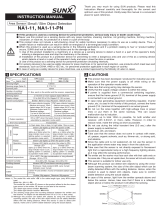
2-3-1 Sensing Range
The safety distance is the minimum distance that must be maintained between
the
ST4-A
□ and the dangerous parts of the machine so that the machine can
be stopped before a human body or an object can reach the dangerous parts.
The safety distance is calculated based on the equation described in the next
page when a person moves perpendicular to the sensing area of the area sensor.
<When installing four units of ST4-A
□
>
Dangerous
part
300mm
300mm
300mm
300mm
Receiver of ST4-A□
Emitter of ST4-A□
Safety distance S (Ds)
Receiver
of ST4-A□
Emitter of
ST4-A□
Dangerous
part
<Top view>
● Be sure to install protection structure around the machine so that
the operator must pass through the sensing area of this device
to reach the dangerous parts of the machine.
Failure to do so can result in death or serious injury.
● Do not use any reflection type or recursive reflection type ar-
rangement.
● Installing multiple sets of this device produces a non-sensing
area or causes mutual interference, which may result in death or
serious injury.
Calculate the safety distance correctly, and always maintain the dis-
tance which is equal to or greater than the safety distance, between
the sensing area of this device and the dangerous parts of the ma-
chine. If the safety distance is miscalculated or if sufcient distance
is not maintained, the machine will not stop quickly before reaching
to the dangerous parts, which can result in death or serious injury.

18 © Panasonic Industrial Devices SUNX Co., Ltd. 2016
Safety Distance
Before designing the system, refer to the relevant standards of the
region where this device is to be used, and then install this device.
Furthermore, the equation described in the following is to be used
only in case the intrusion direction is perpendicular to the sensing
area. In case the intrusion direction is not perpendicular to the sens-
ing area, be sure to refer to the relevant standard (regional stan-
dard, specication of the machine, etc.) for details of the calculation.
[For use in Europe (EU) (as per EN 999)] (Also applicable to ISO 13855)
● Equation 1 S = K × T + C
S : Safety distance (mm)
Minimum required distance between the sensing area surface
and the dangerous parts of the machine
K : Intrusion velocity of operator’s body or object (mm/s)
Taken as 1,600 (mm/s) for calculation
T : Response time of total equipment (s)
T = T
m
+ T
ST4
T
m
:
Maximum halting time of device (s)
T
ST4
:
Response time of this device (s)
C : Additional distance (mm)
EN 999 recommends the height of beam axis and the additional
distance as shown in the table below.
Number of
beam axes
1 2 3 4
Height of
beam axis
(e.g. Height
from the oor)
[mm]
750 400 300 300
900 700 600
1,100 900
1,200
C [mm] 1,200 850 850 850
The max. response time of the machine is from the point that the
machine receives the halt signal from this device to the point that
the dangerous part of the machine stops. The max. response time of
the machine should be timed with the machine to be actually used.

19© Panasonic Industrial Devices SUNX Co., Ltd. 2016
Safety Distance
<In case four units of ST4-A□ are installed>
● Equation 1 S = K × T + C
S : Safety distance (mm)
Minimum required distance between the sensing area surface
and the dangerous parts of the machine
K : Intrusion velocity of operator’s body or object (mm/s)
Taken as 1,600 (mm/s) for calculation
T : Response time of total equipment (s)
T = T
m
+ T
ST4
T
m
:
Maximum halting time of device (s)
T
ST4
:
Response time of this device (s)
C : 850 (mm)
<Calculation Example>
● Calculation Example 1 For use in Europe
(OFF response time: 25ms or less)
S = K × T + C
= 1,600 × (T
m
+ T
ST4
) + 850
= 1,600 × (T
m
+ 0.025) + 850
= 1,600 × T
m
+ 1,600 × 0.025 + 850
= 1,600 × T
m
+ 40 + 850
= 1,600 × T
m
+ 890
In case
ST4-A
□ is installed in a system with a maximum halting time of
0.1 (s)
S = 1,600 × T
m
+ 890
= 1,600 × 0.1
+ 890
= 160
+ 890
= 1,050
Hence, as per the calculations S is 1,050 (mm).

20 © Panasonic Industrial Devices SUNX Co., Ltd. 2016
Safety Distance
Since the calculation above is performed by taking 1 (inch) = 25.4 (mm), there is a
slight difference between the representation in (mm) and that in (inch). Refer to the
relevant standard for the details.
<Reference>
[For use in the United States of America (as per ANSI/RIA 15.06)]
● Equation 2 D
s =
K × T + Dpf
D
s
: Safety distance (mm)
Minimum required distance between the sensing area surface
and the dangerous parts of the machine
K : Intrusion speed {Recommended value in OSHA is 63 (inch/s)
[≈ 1,600 (mm/s)] }
ANSI/RIA 15.06 does not dene the intrusion speed “K.” When
determining K, consider possible factors including physical abil-
ity of operators.
T : Response time of total equipment (s) including OFF response
time of this device: 25ms.
Dpf : Additional distance calculated from the size of the minimum
sensing object of the sensor (mm)
(ANSI/RIA 15.06 stipulates the installation requirements as follows.)
Since the calculation above is performed by taking 1 (inch) = 25.4 (mm), there is a
slight difference between the representation in (mm) and that in (inch). Refer to the
relevant standard for the details.
<Reference>
<In case of an application to “REACH OVER”>
●
Installation requirements
Detectable minimum sensing object:
2.52 (inch) [≈ 64 (mm)] or more,
and under 23.623 (inch) [≈ 600 (mm)]
Undermost beam axis: 11.812 (inch) [≈ 300 (mm)] or less
Topmost beam axis: 35.434 (inch) [≈ 900 (mm)] or more
Dpf: 47.245 (inch) [≈ 1,200 (mm)]
D
s
= K × T + Dpf
= 63 × T + 47.245
In case
ST4-A
□ is installed in a system with a maximum halting time of
0.5 (s)
D
s
= 63 × T + 47.245
= 63 × 0.5 + 47.245
= 31.5 + 47.245
= 78.745 (inch)
= 2,000.123 (mm)
≈ 2,001 (mm)
Hence, as per the calculations D
s
is 2,001 (mm).
11.812 inch
(≈ 300mm) or less
35.434 inch
(≈ 900mm)
or more
Undermost
beam axis
Topmost beam axis
/