
bThe illustrations used for explaining operations in this manual show the buttons of
the remote control unit.
The same operations can be performed using the buttons with the same names on
the main unit panel.
b Les illustrations des boutons présentes dans ce manuel servent à expliquer le
fonctionnement de la télécommande.
Vous pouvez contrôler l’appareil à l’aide du bouton portant le même nom sur la
façade de l’appareil.
AV SURROUND RECEIVER
AVR-890
Owner’s Manual
Manuel de l’Utilisateur
GraphicalUserInterface
English
Use this manual in combination with the
operating guide displayed on the GUI screen.
Menu Map (vpage 20)
Examples of GUI Menu Screen Displays (vpage 21)
Remote Control Unit Operations (vpage 55)
Français
Utilisez ce manuel en même temps que le guide
d’utilisation affiché sur l’écran GUI (Interface
graphique).
Plan du menu (vpage 20)
Exemples d’affichage sur écran et d’affichage avant
(vpage 21)
Fonctionnement de la télécommande (vpage 55)

n
SAFETY PRECAUTIONS
CAUTION
RISK OF ELECTRIC SHOCK
DO NOT OPEN
CAUTION:
TO REDUCE THE RISK OF ELECTRIC SHOCK, DO NOT REMOVE
COVER (OR BACK). NO USER-SERVICEABLE PARTS INSIDE.
REFER SERVICING TO QUALIFIED SERVICE PERSONNEL.
The lightning flash with arrowhead symbol, within an equilateral
triangle, is intended to alert the user to the presence of
uninsulated “dangerous voltage” within the product’s enclosure
that may be of sufficient magnitude to constitute a risk of electric
shock to persons.
The exclamation point within an equilateral triangle is intended
to alert the user to the presence of important operating
and maintenance (servicing) instructions in the literature
accompanying the appliance.
WARNING:
TO REDUCE THE RISK OF FIRE OR ELECTRIC SHOCK, DO NOT
EXPOSE THIS APPLIANCE TO RAIN OR MOISTURE.
ENGLISH FRANCAIS
I
CAUTION:
HOT SURFACE. DO NOT TOUCH.
The top surface over the internal heat sink may become
hot when operating this product continuously.
PRECAUTION:
SURFACE CHAUDE. NE PAS TOUCHER.
La surface supérieure du dissipateur de chaleur peut
devenir chaude si vous utilisez ce produit en continu.
IMPOTANT SAFETY
INSTRUCTIONS
1. Read these instructions.
2. Keep these instructions.
3. Heed all warnings.
4. Follow all instructions.
5. Do not use this apparatus near water.
6. Clean only with dry cloth.
7. Do not block any ventilation openings.
Install in accordance with the manufacturer’s instructions.
8. Do not install near any heat sources such as radiators, heat registers,
stoves, or other apparatus (including amplifiers) that produce heat.
9. Do not defeat the safety purpose of the polarized or grounding-type plug. A
polarized plug has two blades with one wider than the other. A grounding
type plug has two blades and a third grounding prong. The wide blade or the
third prong are provided for your safety. If the provided plug does not fit into
your outlet, consult an electrician for replacement of the obsolete outlet.
10. Protect the power cord from being walked on or pinched particularly at
plugs, convenience receptacles, and the point where they exit from the
apparatus.
11. Only use attachments/accessories specified by the manufacturer.
12. Use only with the cart, stand, tripod, bracket, or table
specified by the manufacturer, or sold with the apparatus.
When a cart is used, use caution when moving the cart/
apparatus combination to avoid injury from tip-over.
13. Unplug this apparatus during lightning storms or when
unused for long periods of time.
14. Refer all servicing to qualified service personnel.
Servicing is required when the apparatus has been damaged in any way,
such as power-supply cord or plug is damaged, liquid has been spilled or
objects have fallen into the apparatus, the apparatus has been exposed to
rain or moisture, does not operate normally, or has been dropped.
15. Batteries shall not be exposed to excessive heat such as sunshine, fire or
the like.
CAUTION:
• The ventilation should not be impeded by covering the ventilation
openings with items, such as newspapers, tablecloths, curtains,
etc.
• No naked flame sources, such as lighted candles, should be
placed on the unit.
• Observe and follow local regulations regarding battery disposal.
• Do not expose the unit to dripping or splashing fluids.
• Do not place objects filled with liquids, such as vases, on the
unit.
ATTENTION:
• La ventilation ne doit pas être gênée en recouvrant les ouvertures
de la ventilation avec des objets tels que journaux, rideaux, tissus,
etc.
• Aucune flamme nue, par exemple une bougie, ne doit être placée
sur l’appareil.
• Veillez à respecter les lois en vigueur lorsque vous jetez les piles
usagées.
• L’appareil ne doit pas être exposé à l’eau ou à l’humidité.
• Ne pas poser d’objet contenant du liquide, par exemple un vase,
sur l’appareil.
CAUTION:
To completely disconnect this product from the mains, disconnect
the plug from the wall socket outlet.
The mains plug is used to completely interrupt the power supply to
the unit and must be within easy access by the user.
PRECAUTION:
Pour déconnecter complètement ce produit du courant secteur,
débranchez la prise de la prise murale.
La prise secteur est utilisée pour couper complètement
l’alimentation de l’appareil et l’utilisateur doit pouvoir y accéder
facilement.

• Avoid high temperatures.
Allow for sufficient heat dispersion when
installed in a rack.
• Eviter des températures élevées.
Tenir compte d’une dispersion de chaleur
suffisante lors de l’installation sur une
étagère.
• Handle the power cord carefully.
Hold the plug when unplugging the cord.
• Manipuler le cordon d’alimentation avec
précaution.
Tenir la prise lors du débranchement du
cordon.
• Keep the unit free from moisture, water,
and dust.
• Protéger l’appareil contre l’humidité, l’eau
et la poussière.
• Unplug the power cord when not using the
unit for long periods of time.
• Débrancher le cordon d’alimentation
lorsque l’appareil n’est pas utilisé pendant
de longues périodes.
* (For apparatuses with ventilation holes)
• Do not obstruct the ventilation holes.
• Ne pas obstruer les trous d’aération.
• Do not let foreign objects into the unit.
• Ne pas laisser des objets étrangers dans
l’appareil.
• Do not let insecticides, benzene, and
thinner come in contact with the unit.
• Ne pas mettre en contact des insecticides,
du benzène et un diluant avec l’appareil.
• Never disassemble or modify the unit in
any way.
• Ne jamais démonter ou modifier l’appareil
d’une manière ou d’une autre.
n
NOTE ON USE / OBSERVATIONS RELATIVES A L’UTILISATION
FCC INFORMATION (For US customers)
1. PRODUCT
This product complies with Part 15 of the FCC Rules. Operation is subject to the following two conditions: (1) this
product may not cause harmful interference, and (2) this product must accept any interference received, including
interference that may cause undesired operation.
2. IMPORTANT NOTICE: DO NOT MODIFY THIS PRODUCT
This product, when installed as indicated in the instructions contained in this manual, meets FCC requirements.
Modification not expressly approved by DENON may void your authority, granted by the FCC, to use the product.
3. NOTE
This product has been tested and found to comply with the limits for a Class B digital device, pursuant to Part 15
of the FCC Rules. These limits are designed to provide reasonable protection against harmful interference in a
residential installation.
This product generates, uses and can radiate radio frequency energy and, if not installed and used in accordance
with the instructions, may cause harmful interference to radio communications. However, there is no guarantee
that interference will not occur in a particular installation. If this product does cause harmful interference to radio or
television reception, which can be determined by turning the product OFF and ON, the user is encouraged to try to
correct the interference by one or more of the following measures:
• Reorient or relocate the receiving antenna.
• Increase the separation between the equipment and receiver.
• Connect the product into an outlet on a circuit different from that to which the receiver is connected.
• Consult the local retailer authorized to distribute this type of product or an experienced radio/TV technician for
help.
This Class B digital apparatus complies with Canadian ICES-003.
Cet appareil numérique de la classe B est conforme à la norme NMB-003 du Canada.
ENGLISHFRANCAIS
II

ENGLISH
Flow of operations through playback ·········································2
Accessories ··················································································2
Cautions on Handling ···································································3
Cautions on Installation ·······························································3
About the Remote Control Unit···················································3
Inserting the Batteries ··································································3
Operating Range of the Remote Control Unit ······························3
Part Names and Functions ···························································4
Front Panel ····················································································4
Display ··························································································5
Rear Panel ·····················································································6
Remote Control Unit ·····································································7
Connections
Important Information ··································································8
Cables Used for Connections ·······················································8
Converting Input video signals for Output
(Video Conversion Function) ·························································9
Installing/Setting the Speakers ················································· 10
Connecting the Speakers ··························································· 11
Connecting Devices ····································································12
Connecting Devices not Equipped with HDMI terminals ········ 13
Once Connections are Completed ············································· 19
Turning the Power On ·································································19
Turning the Power Off ································································· 19
Selecting the Input Source ·························································19
Settings
Playback
Getting Started
Checking the Status (Information) ·····························51
Playing Components ···································································40
Playing Blu-ray Disc / DVD Players ··············································40
iPod
®
Playback ···········································································40
Listening to FM/AM Broadcasts ·················································41
Listening to SIRIUS Satellite Radio Programs ····························42
Operations During Playback ························································44
Selecting the Surround Mode ····················································44
q Playing Sources According to the Sources’ Audio Signal
Format/Number of Channels (Standard Playback) ·············· 44
w Playing in a DENON Original Surround Mode ························45
e Direct Playback ·······································································45
r Stereo Playback ······································································46
t Playing the Pure Direct Mode ················································46
Adjusting the Sound and Picture Quality
(Audio/Video Adjust) ··································································46
Adjusting the Sound (Audio Adjust) ············································46
Adjusting the Tone (Tone Control) ···············································48
Adjusting MultEQ
®
, Dynamic EQ™, Dynamic Volume™
Settings (Audyssey Settings) ······················································48
Adjust Tonal Quality for Each Speaker Using Graphic Equalizer
(Manual EQ) ················································································50
Restoring Compressed Audio to Nearly Pre-compressed
Conditions for Playback (RESTORER) ·········································50
Adjusting the Audio Delay Time while Watching the Picture
(Audio Delay) ···············································································50
Adjusting the Picture Quality (Picture Adjust) ·····························51
Menu Map ····················································································20
Examples of GUI Menu Screen Displays ···································21
Making the Optimum Settings for the Connected Speakers
Automatically (Audyssey™ Auto Setup) ··································22
Making detailed settings (Manual Setup)·································27
Making the Input Settings (Input Setup) ··································34
Convenient functions
HDMI Control Function ·······························································52
Setting the Power to Standby After a Certain Amount of
Time (Sleep Timer Function) ······················································52
Adjust the Volume of the Different Speakers ··························53
Saving Frequently Used Settings (Quick Select Function) ·····53
MAIN ZONE settings ··································································53
ZONE2 settings···········································································53
Various Memory Functions ························································53
Playing 2-Channel Sound in ZONE2
(Multizone Function)··························································54
Operating the Connected Devices by Remote
Control Unit
Registering Preset Codes ···························································55
Operating Registered Devices ···················································55
Assigning buttons that are Not Used to Operate Other
Devices (Punch Through Function)············································57
Other Information ·······························································58
Troubleshooting···································································65
Restoring All the Settings to as They were at the Time of
Purchase (Resetting the Microprocessor) ·································68
Specifications ········································································68
n Contents
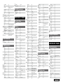
List of preset codes ··································End of this manual

2
ENGLISH
Getting Started
Connections Playback Remote Control Information Troubleshooting
Specifi cationsMulti-ZoneSettings
Perform the operations leading to playback on the AVR-890 in the
order shown below.
Connections
⇩
Installing/Setting the Speakers (vpage 10)
Connecting Devices (vpage 12)
⇩
Turning the Power On (vpage 19)
Flow of operations through
playback
Getting Started
Thank you for purchasing this DENON product. To ensure proper
operation, please read this owner’s manual carefully before using the
product.
After reading them, be sure to keep them for future reference.
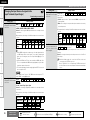
q Owner’s manual ......................................................................1
w Getting Started ........................................................................1
e Warranty (for North America model only) ................................ 1
r Service station list ...................................................................1
t Power cord (Cord length: Approx. 5.6 ft / 1.7 m) .................... 1
y Remote control unit (RC-1117) ................................................ 1
u R6/AA batteries ....................................................................... 2
i FM indoor antenna ..................................................................1
o AM loop antenna .....................................................................1
Q0 Setup microphone
(DM-A409, Cord length: Approx. 25 ft / 7.6 m) .......................1
Check that the following parts are supplied with the product.
t
i o
y
Q0
Accessories
⇩
Connecting the Speakers (vpage 11)
Playback
⇩
Playing Components (vpage 40)
⇩
Selecting the Surround Mode (vpage 44)
Audyssey™ Auto Setup (vpage 22)
Settings
Manual Setup (vpage 27)
Perform “Manual Setup” as necessary.b
Input Setup (vpage 34)
Getting Started
⇩
Selecting the Input Source (vpage 19)
Adjusting the Sound and Picture Quality
(vpage 46)

ENGLISH
Getting Started Connections Playback Remote Control Information Troubleshooting SpecificationsMulti-ZoneSettings
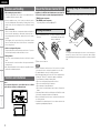
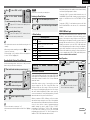
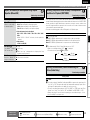
In addition to the AVR-890, the included remote control unit (RC-
1117) can also be used to operate the equipment listed below.
q DENON system components
w Non-DENON system components
• By setting the preset memory (vpage 55)
30°
30°
Approx. 23 feet / 7 m
Point the remote control unit at the remote sensor when operating it.
NOTE
The set may function improperly or the remote control unit may not
operate if the remote control sensor is exposed to direct sunlight,
strong artificial light from an inverter type fluorescent lamp or infrared
light.
NOTE
• Replace the batteries with new ones if the set does not operate
even when the remote control unit is operated close to the unit.
• The supplied batteries are only for verifying operation.
• When inserting the batteries, be sure to do so in the proper direction,
following the “q” and “w” marks in the battery compartment.
• To prevent damage or leakage of battery fluid:
• Do not use a new battery together with an old one.
• Do not use two different types of batteries.
• Do not attempt to charge dry batteries.
• Do not short-circuit, disassemble, heat or dispose of batteries in
flames.
• If the battery fluid should leak, carefully wipe the fluid off the inside
of the battery compartment and insert new batteries.
• Remove the batteries from the remote control unit if it will not be in
use for long periods.
• Used batteries should be disposed of in accordance with the local
regulations regarding battery disposal.
Operating Range of the Remote Control
Unit
• Before turning the power switch on
Check once again that all connections are correct and that there are
no problems with the connection cables.
•
Power is supplied to some of the circuitry even when the unit is
set to the standby mode. When traveling or leaving home for long
periods of time, be sure to unplug the power cord from the power
outlet.
• About condensation
If there is a major difference in temperature between the inside of
the unit and the surroundings, condensation (dew) may form on
the operating parts inside the unit, causing the unit not to operate
properly.
If this happens, let the unit sit for an hour or two with the power
turned off and wait until there is little difference in temperature
before using the unit.
• Cautions on using mobile phones
Using a mobile phone near this unit may result in noise. If so, move
the mobile phone away from this unit when it is in use.
• Moving the unit
Turn off the power and unplug the power cord from the power
outlet.
Next, disconnect the connection cables to other system units before
moving the unit.
•
Note that the illustrations in these instructions may differ from the
actual unit for explanation purposes.
Note:
For proper heat dispersal, do not install this unit in a confined
space, such as a bookcase or similar enclosure.
b Note
b
Wall
b
b
Cautions on Handling
Cautions on Installation
About the Remote Control Unit
Getting Started
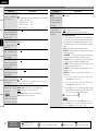
e Put the rear cover back on.
q Lift the clasp and remove the
rear cover.
w Load the two batteries properly
as indicated by the marks in the
battery compartment.
R6/AA
Inserting the Batteries

Connections Playback Remote Control Information Troubleshooting
Specifications
ENGLISH
Multi-ZoneSettings
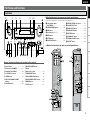
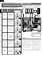
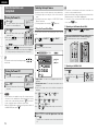
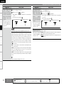
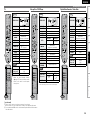
Part Names and Functions
Front Panel
q
e
o
,
Q0
Q1
u
o
,
Q0
i
y
r
o
,
Q0
Q0
t
w
Q2
Q4
Q3
Q5
q
Q7Q6
Q0 Q1 Q2 Q3 Q4 Q5 W9W8 E0
Q8
w e r t y
Q9
W0
u
i
W1W2W3W4W5W6
o
W7
i MASTER VOLUME control knob ··············· (40)
o SOURCE SELECT knob ······························ (19)
Q0 ZONE2 SELECT button ···························(54)
Q1 ZONE2 ON/OFF button ···························(54)
Q2 RESTORER button ······································ (50)
Q3 DYNAMIC EQ™ button ······························ (49)
Q4 DYNAMIC VOLUME™ button ··················· (49)
Q5 MULTEQ
®
button ······································· (48)
Buttons, terminals and displays only provided on the main unit
Button that function in the same way as remote control buttons
For buttons not explained here, see the page indicated in parentheses ( ).
q Power operation button
(ON/STANDBY) ·········································· (19)
w SURROUND MODE buttons ······················ (44)
e MENU button ·············································· (20)
r Cursor buttons (uio p) ························· (20)
t ENTER button ············································· (20)
y RETURN button ·········································· (20)
u QUICK SELECT buttons ····························· (53)
q
e
o
,
Q0
Q1
u
o
,
Q0
i
y
r
o
,
Q0
Q0
t
w
Q2
Q4
Q3
Q5
Front Rear
n Buttons that function in the same way as front panel buttons
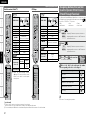
W3 MASTER VOLUME indicator
W4 Display
W5 Remote control sensor ································ (3)
W6 TUNING PRESET button ···························· (42)
W7 SOURCE MODE SELECT button ··············· (19)
W8 FRONT SPEAKERS SELECT button ··········· (44)
W9 DIMMER button ·········································· (33)
E0 STATUS button ·········································· (51)
Q6 Power indicator ·········································· (19)
Q7 Power switch (hON jOFF) ··············· (19, 68)
Q8 Headphones jack (PHONES) ······················ (44)
Q9 V. AUX INPUT connectors ························· (16)
W0 SETUP MIC jack ·········································· (23)
W1 AUDYSSEY DYNAMIC VOLUME™
indicator ······················································ (49)
W2 HD AUDIO indicator ··································· (45)
Getting Started

Connections Playback Remote Control Information Troubleshooting Specifications
ENGLISH
Multi-ZoneSettings
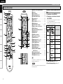
Part Names and Functions
ioQ5 Q0Q1
Q6
Q2Q4
Q3
Q7 u
wq e r t y
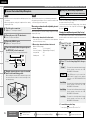
q Input audio signal indicators
w Input signal channel indicators
These light when digital signals are input.
When playing HD Audio sources, the“ ”
indicator lights when an extension channel (a
channel other than the front, center, surround,
surround back or LFE channel) is input. If there
are two or more extension channels, the “ ”
and “ ” indicators light.
e Information display
The input source name, surround mode, setting
values and other information are displayed
here.
r Output signal channel indicators
t Front speaker indicator
These light according to the settings of the
front A and B speakers (vpage 44).
y Monitor output indicators
These light according to the HDMI monitor
output setting.
u QUICK SELECT indicators
These light when the Quick Select function is
set (vpage 53).
i Master volume indicator
o MUTE indicator
Lights when the muting mode is set (vpage
44).
Q0 AUDYSSEY indicator
These light as shown below in the different
modes (vpage 48).
: During “MultEQ” operation
: During “MultEQ” , “Dynamic EQ”
operation
: During “MultEQ” , “Dynamic EQ”,
“Dynamic Volume” operation
b When speakers settings are changed after
Audyssey™ Auto Setup, either the indicators’
frame turns off or all the indicators turn off.
Q1 SLEEP TIMER indicator
Lights when the sleep timer is operating
(vpage 52).
Q2 RESTORER indicator
Lights during “RESTORER” operation (vpage
50).
Q3 Input mode indicators
Q4 ZONE2 indicator
Lights when signals are being output to the
ZONE2 (vpage 54).
Q5 HDMI indicator
Lights when HDMI input signals are detected
(vpage 13).
Q6 Decoder indicators
The indicator for the currently operating decoder
lights.
Display
Getting Started
Q7 Tuner reception mode indicators
This lights according to the reception conditions
when the input source is set to “TUNER”.
• AUTO
This lights when in the auto tuning mode.
• STEREO
In the FM mode, this lights when receiving
analog stereo broadcasts.
• TUNED
This lights when the broadcast is properly
tuned in.

Connections Playback Remote Control Information Troubleshooting
Specifications
ENGLISH
Multi-ZoneSettings
q w e r t y
i uQ1Q2Q5Q6
o
Q0
Q3
Q4
Part Names and Functions
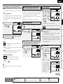
Rear Panel
q Digital audio connectors ···························(15)
w Analog audio connectors ··························(14)
e SIGNAL GND terminal ······························(15)
r REMOTE CONTROL jacks ·························(18)
t PRE OUT connector ···································(11)
y ZONE2 connectors ····································(54)
u AC OUTLETS ··············································(18)
i AC inlet (AC IN) ··········································(18)
o Speaker terminals ·····································(11)
Q0 FM/AM antenna terminals ·······················(17)
Q1 EXT. IN connectors ····································(16)
Q2 COMPONENT VIDEO connectors ·············(14)
Q3 HDMI connectors ·······································(13)
Q4 SIRIUS connector ······································(17)
Q5 VIDEO/S-VIDEO connectors ·····················(15)
Q6 Control dock for iPod
DOCK CONTROL jack ································(14)
Getting Started

Connections Playback Remote Control Information Troubleshooting Specifications
ENGLISH
Multi-ZoneSettings
Part Names and Functions
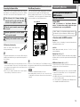
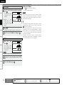
Remote Control Unit
q
w
e
r
t
y
u
o
Q0
t
i
Q1
Q2
Q3
Q4
Q5
Q6
Q7
t
Q8
W0
W1
W8
W7
W4
W5
W6
W2
W3
NOTE
Buttons on the back panel may operate when the
back lid is pressed.
q Remote control signal transmitter
w Indicator ····················································· (55)
e Power buttons ··········································· (19)
r QUICK SELECT buttons ···························· (53)
t SOURCE SELECT button ·························· (19)
y System buttons ········································· (55)
u MENU button ············································(20)
i Cursor buttons (uio p) ························ (20)
o SEARCH button ········································· (41)
Q0 DEVICE SELECT switches ··················· (40, 55)
Q1 Master volume control buttons ··············· (40)
Q2 MUTING button ········································· (44)
Q3 Channel level adjustment button ············ (53)
Q4 RETURN button ········································· (20)
Q5 ENTER button ············································ (20)
Q6 ZONE2 power button ································ (54)
Q7 Tuner operation buttons ·························· (42)
Q8 MULTEQ
®
button ····································· (48)
Q9 Number buttons (0 ~ 9, +10) ···················· (55)
W0 MAIN ZONE power buttons ····················· (19)
W1 INPUT MODE button ································· (37)
W2 SLEEP TIMER button ································(52)
W3 VIDEO SELECT button ······························ (36)
W4 RESTORER button ····································· (50)
W5 FRONT HEIGHT SPEAKER
ON/OFF button ·········································· (48)
W6 Surround mode buttons ··························· (44)
W7 DYNAMIC VOLUME™ button ·················· (49)
W8 DYNAMIC EQ™ button ····························· (49)
Q9
For buttons not explained here, see the page
indicated in parentheses ( ).
RearFront
Operations Possible by Remote Control
Unit
Operations on the AVR-890
Operations on six devices other that
the AVR-890
Preset the remote control codes of the devices
to be operated (vpage 55).
Switch two device selector switches according
to the devices to be operated.
Position of switches
Operable devices
AVR-890
(MAIN ZONE)
iPod
AVR-890 (ZONE2)
TV
Blu-ray disc player
or
DVD Player
DVD recorder
or
Video deck
Satellite receiver
or
Cable TV
CD player
ZONE2 operations (vpage 54)
Punch through setting (vpage 57)
n
n
•
•
n
n
Getting Started

8
ENGLISH
Getting Started
Playback Remote Control Information Troubleshooting
Specifi cationsMulti-ZoneSettings
Connections for all compatible audio and video signal formats
are described in this owner’s manual. Please select the types of
connections suited for the equipment you are connecting.
After connections are completed, certain settings must be made on
the receiver. Make the settings indicated “
Set as necessary
”
for the individual items.
Select the cables according to the equipment being connected.
Important Information
Cables Used for Connections
Audio and video cables
HDMI
connections
HDMI cable
Audio cables
Coaxial digital
connections
Coaxial digital cable
Optical digital
connections
Optical cable
Analog
connections
R
L
R
L
Stereo pin-plug cable
Analog
connections
(monaural, for
subwoofer)
Pin-plug cable
Speaker
connections
Speaker cables
Video cables
Component
video
connections
Component video cable
S-Video
connections
S-Video cable
Video
connections
75 Ω/ohms pin-plug video cable
(White)
(Red)
n HDMI (vpage 12)
n Monitor (TV) (vpage 13)
n Playback Components
• Blu-ray Disc player / DVD player (vpage 14)
• iPod
®
(vpage 14)
• CD Player (vpage 14)
• Record Player (vpage 15)
n Recording Components
• Digital Video Recorder (vpage 15)
• Video Cassette Recorder (vpage 15)
n SAT/CABLE Tuner (vpage 16)
n Other Devices
• Video Camera / Game Console (vpage 16)
• Component with Multi-channel Output connectors
(vpage 16)
• SIRIUS Connector (vpage 17)
• Antenna terminals (vpage 17)
• External Controller (vpage 18)
n Power Cord (vpage 18)
Connection Flown
Turning the Power On (vpage 19)
Installing/Setting the Speakers (vpage 10)
Connecting Devices (vpage 12)
(Yellow)
(Green)
(Blue)
(Red)
Connections
NOTE
• Do not plug in the power cord until all connections have been
completed.
• When making connections, also refer to the operating instructions
of the other components.
• Be sure to connect the left and right channels properly (left with
left, right with right).
• Do not bundle power cords together with connection cables. Doing
so can result in humming or noise.
Connecting the Speakers (vpage 11)
Connecting Devices not Equipped with HDMI
terminals (vpage 13)
Connections

Getting Started Playback Remote Control Information Troubleshooting Specifications
ENGLISH
Multi-ZoneSettings
Converting Input video signals for Output
(Video Conversion Function)
The AVR-890 is equipped with four types of video input/output terminals (HDMI, Component video, S-
Video and video).
Use the terminals according to the devices to be connected.
This function automatically converts various formats of video signals input to the AVR-890 into the format
used to output the video signals from the AVR-890 to a monitor.
• The video conversion function supports the NTSC, PAL, SECAM, NTSC 4.43, PAL-N, PAL-M and PAL-60
formats.
• The resolution of the video signal input to the AVR-890’s HDMI terminal is the resolution set at
“Resolution” (vpage 36). (1080p HDMI signals and 1080p component signals are output at 1080p,
regardless of the setting.)
Important Information
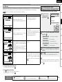
Examples of GUI menu
Menu screen• Status display screen•
When the input source is
switched
When the volume is adjusted
M E N U
A u d i o / V i d e o A d j u s t
I n f o r m a t i o n
A u t o S e t u p
M a n u a l S e t u p
I n p u t S e t u p
A d j u s t v a r i o u s a u d i o a n d v i d e o p a r a m e t e r s
I n p u t D V D A u t o
M o d e S T E R E O
M a s t e r V o l u m e - 8 0 . 0 d B
Status display: The operating status is displayed temporarily on the
screen when the input source is switched or the
volume is adjusted.
n
HDMI connector
Component video
connectors
S-Video connector
Video connector
Monitor
HDMI connector
Component video
connectors
S-Video connector
Video connector
HDMI connector
Component video
connectors
Video connector
HDMI connector
Component video
connectors
Video connector
Video device
AVR-890
Output
Input
(IN)
Output
(MONITOR OUT)
Input
S-Video connector S-Video connector
: When 480i/576i signals are input
Resolutions of HDMI-compatible TVs can be checked at “HDMI Information” (vpage 51).
NOTE
HDMI signals cannot be converted into analog signals.
When a non-standard video signal from a game machine or some other source is input, the video
conversion function might not operate.
480p/576p/1080i/720p/1080p component video input signals cannot be converted into S-Video or Video
format.
•
•
•
Set when using the video conversion function.
“Video Convert” (vpage 36)
Set when changing the resolution of the video signal.
“Resolution” (vpage 36)
•
•
Set as Necessary
Connections

0
ENGLISH
Getting Started
Playback Remote Control Information Troubleshooting
SpecificationsMulti-ZoneSettings
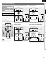
Installing/Setting the Speakers
NOTE
It is not possible to use the front height speakers and
surround back speakers simultaneously.
• The AVR-890 is compatible with various types of
surround playback.
• Decide on the surround modes to be played on
the AVR-890 before making connections and
settings.
Below we introduce examples of speaker layouts. Refer
to these to arrange your speakers according to their
type and how you want to use them.
Installing All the Speakers
Surround back speakers
Center
speaker
Front
speakers
Subwoofer
Front Height speakers
Surround
speaker
Surround
speaker
z
1
z4
z
5
z
2
z
3
Monitor
Center speaker
Subwoofer
G
As seen from above
H
z1: 22 ~ 30˚
z2: 90˚
z3: 110˚
Surround back
speaker
G
As seen from the side
H
Surround speakers
Surround
speaker
Front
speaker
2 to 3 feet /
60 to 90 cm
Point slightly
downwards
Surround back
speakers
Front speakers
When 7.1ch (Surround Back Speaker) Connectedn
z4: 30˚
z5: 45˚
z
1
z
2
z3
Front speakers
G
As seen from above
H G
As seen from the side
H
Monitor
Center speaker
z1: 22 ~ 30˚
z2: 90˚
z3: 110˚
Subwoofer
Surround speakers
Surround back
speaker
Front
speaker
Surround
speaker
Surround back
speaker
Point slightly
downwards
2 to 3 feet /
60 to 90 cm
z
1
z
2
Surround speakers
Front speakers
Monitor
Center speaker
Subwoofer
z1: 22 ~ 30˚
z2: 120˚
Front
speaker
Surround
speaker
2 to 3 feet /
60 to 90 cm
G
As seen from above
H G
As seen from the side
H
When 6.1ch Connectedn
When 5.1ch Connectedn
z4
z
2
z
1
z
3
Front speakers
Subwoofer
Monitor
Surround speakers
Center speaker
Front height speakers
G
As seen from above
H
z1: 30˚
z2: 45˚
Surround
speaker
Front height
speaker
Point slightly
downwards
2 to 3 feet /
60 to 90 cm
G
As seen from the side
H
Front speaker
When 7.1ch (Front Height Speaker) Connectedn
z3: 90˚
z4: 110˚
a Determine the Speaker Layout
Connections

Getting Started Playback Remote Control Information Troubleshooting Specifications
ENGLISH
Multi-ZoneSettings
Protection circuit
If the core wires touch the rear panel and the screws
etc., or the ± sides touch each other, the protection
circuit will be activated and the power indicator will
flash red at intervals of 0.5 secs.
If the protection circuit is activated, the speaker
output is isolated, and the power supply goes to
the standby state. If the power supply is turned off,
after the power supply cord is withdrawn, please
confirm that speaker cable and input cable are
connected.
Also, if replaying large sound levels by using
a speaker having an impedance less than that
specified (eg, 4 Ω/ohms), the temperature will rise,
and the protection circuit might be activated. The
power supply will go into the standby state, and the
power indicator will flash red at 2 second intervals.
In this case, please switch off the power supply,
and wait until the AVR-890 has cooled down, and
the surrounding ventilation is good.
Even if there are no problems with the surrounding
ventilation and connections, in the event of the
protection circuit becoming activated, due to
thinking that the AVR-890 has failed, please contact
DENON Service center after switching off.
w q
w q w q
*/
(L) (R)
w qw q
(R) (L)
w qw q
(R) (L)
Subwoofer with
built-in amplifier
Center
speaker
Surround
speakers
Front speakers
A
Front speakers
B
For connections of the SURR. BACK/AMP
ASSIGN speaker terminals, see “Amp Assign”
(vpage 27).
Connecting the Speakers
s
Set the “Amp Assign” Mode According to the Speaker Layout
The signals output from the AVR-890’s SURR. BACK/AMP ASSIGN speaker terminals can be
switched to signals of the surround mode being used (vpage 27 “Amp Assign”).
Amp assign mode
(vpage 27)
SURR. BACK/AMP ASSIGN
Speaker connections
Example of speaker installation
Normal
Normal
Normal
Front Height
Front A Bi-Amp
or
Front B Bi-Amp
ZONE2
(Default)
MAIN ZONE ZONE2
Front Height
speakers
Surround back
speakers
Surround back
speakers
Not connected
Front A or B
speakers
b For connections, see
“About bi-amp connections”
(vpage 12).
(7.1)
(6.1)
(5.1)
(7.1)
(5.1)
(5.1)
(2)
b Connect to the “L” speaker
terminal.
b Set “S.Back” (vpage 28)
to “1spkr”.
b
Set the “S.Back” setting
(vpage 28) to “None”.
Installing/Setting the Speakers
ZONE2
speakers
Connections

2
ENGLISH
Getting Started
Playback Remote Control Information Troubleshooting
SpecificationsMulti-ZoneSettings
Connecting Devices
NOTE
• These functions will not work if the device connected to the HDMI
terminal does not support Deep Color or x.v.Color signal transfer or
the Auto Lip Sync function.
• The HDMI control function may not work depending on the device it
is connected to and its settings.
• You cannot operate a TV or Blu-ray Disc player / DVD player that is
not compatible with the HDMI control function.
Connecting Devices Equipped with
HDMI terminals
Important Information
n About HDMI
“HDMI” is the abbreviation of “High Definition Multimedia
Interface”. This interface allows transfer of digital video signals
and digital audio signals over a single HDMI cable.
n Functions usable with HDMI connections
Deep Color
Eliminates on-screen color banding, for smooth tonal transitions and
subtle gradations between colors.
x.v.Color
Enables displays with natural, vivid colors. “x.v.Color” is a Sony
registered trademark.
Auto Lip Sync (vpage 30)
HDMI 1.3 incorporates an automatic video/audio synching capability
that allows devices to perform this synchronization automatically with
total accuracy.
HDMI control function (vpage 30, 52)
This function allows you to operate external devices from the receiver
and operate the receiver from external devices.
“HDMI”, “HDMI logo” and “High-Definition Multimedia Interface”
are trademarks or registered trademarks of HDMI Licensing LLC.
NOTE
• Connect the speaker cables in such a way that they do not stick out
of the speaker terminals. The protection circuit may be activated if
the core wires touch the rear panel or if the + and – sides touch each
other (v“Protection circuit”).
• Never touch the speaker terminals while the power supply is
connected. Doing so could result in electric shock.
1
Peel off about 0.03 ft / 10 mm of sheathing
from the tip of the speaker cable, then either
twist the core wire tightly or terminate it.
2
Turn the speaker terminal counterclockwise
to loosen it.
3
Insert the speaker cable’s core wire to the hilt
into the speaker terminal.
4
Turn the speaker terminal clockwise to tighten
it.
Use speakers with an impedance of 6 to 16 Ω/ohms. When using front
A and B speakers simultaneously, use speakers with an impedance of
12 to 16 Ω/ohms.
n When using a banana plug
Tighten the speaker terminal firmly before
inserting the banana plug.
Connecting the Speaker Cables
Carefully check the left (L) and right (R) channels and + (red) and –
(black) polarities on the speakers being connected to the AVR-890,
and be sure to interconnect the channels and polarities correctly.
wq wq
(R) (L)
When in the “Front A Bi-Amp” and “Front B Bi-Amp” modes, the
same signals are output from the front speaker terminals and the AMP
ASSIGN terminals.
About Bi-amp Connections
These connections make for higher quality playback sound with no
interference between the signals of the bass and treble units.
When the amplifier assignment mode is set to “Front A Bi-Amp” or
“Front B Bi-Amp”, connect as shown below. (The illustration shows a
connection example for the front B Bi-Amp speakers.)
NOTE
• Use speakers compatible with bi-amp connections.
• When making bi-amp connections, be sure to remove the short-
circuiting plate or wire between the speaker’s woofer and tweeter
terminals.
Front speakers B
Connecting the Speakers
AVR-890
Connections

ENGLISH
Getting Started Playback Remote Control Information Troubleshooting SpecificationsMulti-ZoneSettings
• Select the terminal to use and connect the device.
• For video connections, see “Converting input video signals for output
(Video Conversion Function)” (vpage 9).
*/
7*%&0
$0.10/&/57*%&0
: 1# 13
7*%&0
*/
"6%*0
015*$"-
065
47*%&0
*/
Monitor (TV)
The component video connectors may be indicated differently on your
monitor. For details, see the monitor’s operating instructions.
Monitor (TV)
For instructions on HDMI connections, see “Connecting Devices
Equipped with HDMI terminals” on page 12.
Connecting devices
NOTE
• If the menu “HDMI Audio Out” setting (vpage 30) is set to
“Amp”, the sound may be interrupted when the monitor’s power is
turned off.
• The audio signal from the HDMI output terminal (sampling
frequency, number of channels, etc.) may be limited by the HDMI
audio specifications of the connected device regarding permissible
inputs.
• Use a cable on which the HDMI logo is indicated (a certified HDMI
product) for connection to the HDMI connector. Normal playback
may not be possible when using a cable other than one on which the
HDMI logo is indicated (a non-HDMI-certified product).
• When the AVR-890 is connected to other devices with HDMI cables,
also connect the AVR-890 and TV using an HDMI cable.
• When a device supporting Deep Color signal transfer is connected,
use a cable compatible with HDMI ver.1.3a.
• Video signals are not output if the input video signals do not match
the monitor’s resolution. In this case, switch the Blu-ray Disc player /
DVD player’s resolution to a resolution with which the monitor is
compatible.
The AVR-890 allows connection of inputs from up to 5 HDMI
devices and output to 1 TV.
065
)%.*
065
)%.*
065
)%.*
065
)%.*
065
)%.*
*/
)%.*
Blu-ray
Disc Player
Digital Video
Recorder
Monitor
(TV)
Connections
NOTE
• No sound is output when connected to a device equipped with a
DVI-D terminal. Also make the audio connections.
• Signals cannot be output to DVI-D devices that do not support
HDCP.
• Depending on the combination of devices, the video signals may not
be output.
n Connecting to a device equipped with a DVI-D
terminal
When an HDMI/DVI conversion cable (sold separately) is used, the
HDMI video signals are converted to DVI signals, allowing connection
to a device equipped with a DVI-D terminal.
NOTE
The audio signals output from the HDMI connectors are only the
HDMI input signals.
n Settings related to HDMI connections
Set as necessary. For details, see the respective reference pages.
Input Assign (vpage 35)
Set this when changing the input sources of the different terminals.
HDMI Setup (vpage 30)
Make these settings related to HDMI input/output signals.
• RGB Range
• Auto Lip Sync
• HDMI Audio Out
• HDMI Control
• Standby Source
• Power Off Control
Connecting Devices not
Equipped with HDMI terminals
Game
Console
SAT/CABLE
Tuner
DVD
Player
NOTE
When a device that does not support HDCP is connected, video
signals are not properly output.
n Copyright protection system (HDCP)
The AVR-890 supports HDCP (High-bandwidth Digital Contents
Protection). HDCP is a copyright protection technology for digital video
signals. The devices connected to the AVR-890 must also support
HDCP.
Connections

ENGLISH
Getting Started
Playback Remote Control Information Troubleshooting
SpecificationsMulti-ZoneSettings
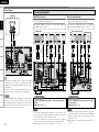
Connecting Devices not Equipped with HDMI terminals
R
L
R
L
"6%*0
"6%*0
3-
065
CD Player
CD Player
Set this to change the input signal to which the input source
is assigned.
“Input Assign” (vpage 35)
Set as necessary
R
L
R
L
7*%&0
$0.10/&/57*%&0
: 1# 13
065
"6%*0
"6%*0
3-
065
065
$0"9*"-
Blu-ray Disc player /
DVD player
NOTE
When connected to a Blu-ray Disc player, and playing Dolby
TrueHD, DTS-HD, Dolby Digital Plus, connect the HDMI.
Set this to change the input signal to which the input source
is assigned.
“Input Assign” (vpage 35)
Set as necessary
Playback Components
Blu-ray Disc player / DVD player
Select the terminal to use and connect the device.
R
L
R
L
Control dock for iPod
With the default settings, the iPod can be used connected to the VCR
(iPod) connector.
Set this to assign the iPod to a terminal other than “VCR
(iPod)”.
“iPod Dock” (vpage 35)
Set as necessary
Control dock for iPod
®
Use a DENON control dock for iPod (ASD-1R, ASD-11R, ASD-3N or
ASD-3W sold separately) to connect the iPod to the AVR-890. For
instructions on the control dock for iPod settings, refer to the control
dock for iPod’s operating instructions.
ASD-3N or
ASD-3W
For instructions on HDMI connections, see “Connecting Devices
Equipped with HDMI terminals” on page 12.
Connections

ENGLISH
Getting Started Playback Remote Control Information Troubleshooting SpecificationsMulti-ZoneSettings
(/%
"6%*0
065
R
L
Turntable
(MM cartridge)
Record Player
The AVR-890 is compatible with record players with an MM
cartridge. When you connect to a record player with an MC
cartridge, use a commercially available MC head amp or a step-
up transformer.
When you increase the volume without connecting the record
player, there may be “booming” noise from the speakers.
•
•
NOTE
The SIGNAL GND terminal of the AVR-890 is not a safety ground
connection. Connect it to reduce noise when noise is excessive.
Note that depending on the record player, connecting the ground
line may have the reverse effect of increasing noise. In this case,
it is not necessary to connect the ground line.
Recording Components
R
L
R
L
R
L
R
L
3- 3-
065
*/
"6%*0"6%*0 7*%&07*%&0
065 */
015*$"-015*$"-
*/
"6%*0"6%*0
065
7*%&0 7*%&0
$0.10/&/57*%&0
: 1# 13
065
DVD Recorder
NOTE
• To record video signals through the AVR-890, use the same type of video
cable for connection between the AVR-890 and the player as the cable used
for connection between the AVR-890 and the recorder.
• Do not connect the output of the component connected to the AVR-890’s
OPTICAL2 output connector to any input connector other than OPTICAL2.
• Digital signals are not output from the analog REC OUT connector.
Set this to change the input signal to which the input source is
assigned.
“Input Assign” (vpage 35)
Set as necessary
Digital Video Recorder
Select the terminal to use and connect the device.
3-
065065
"6%*07*%&0
"6%*0
7*%&0
"6%*0
3-
*/
"6%*0 7*%&0
47*%&0
065
47*%&0
*/
R
L
R
L
R
L
R
L
Video cassette recorder
NOTE
• To record video signals through the AVR-890, use the same
type of video cable for connection between the AVR-890 and
the player as the cable used for connection between the AVR-
890 and the recorder.
• Digital signals are not output from the analog REC OUT
connector.
Set this to change the input signal to which the input
source is assigned.
“Input Assign” (vpage 35)
Set as necessary
Video Cassette Recorder
Select the terminal to use and connect the device.
For instructions on HDMI connections, see “Connecting Devices Equipped
with HDMI terminals” on page 12.
For instructions on HDMI connections, see “Connecting
Devices Equipped with HDMI terminals” on page 12.
Connecting Devices not Equipped with HDMI terminals
Connections

ENGLISH
Getting Started
Playback Remote Control Information Troubleshooting
SpecificationsMulti-ZoneSettings
065
"6%*0 7*%&0
7*%&0"6%*0
3-
065 065
$0"9*"-
47*%&0
065
R
L
R
L
SAT/CABLE Tuner
SAT/CABLE Tuner
Connecting Devices not Equipped with HDMI terminals
Set this to change the input signal to which the input source
is assigned.
“Input Assign” (vpage 35)
Set as necessary
Select the terminal to use and connect the device.
For instructions on HDMI connections, see “Connecting Devices
Equipped with HDMI terminals” on page 12.
R
L
R
L
065
"6%*07*%&0
7*%&0 "6%*0
3-
065
065
015*$"-
47*%&0
065
Video camera /
Game console
Other Devices
Video Camera / Game Console
R
L
R
L
R
L
R
L
R
L
R
L
46#
800'&3
$&/5&3 463306/%
#"$,
3-
463306/%
3-
'30/5
3-
"6%*0
Blu-ray Disc player / DVD player /
External decoder
To play analog signals input from the external input (EXT. IN)
terminal, set “Input Mode” (vpage 37) on the menu to “EXT.
IN”.
“EXT. IN” can also be selected with .
Set as necessary
Component with Multi-channel Output connectors
The video signal can be connected in the same way as a Blu-ray Disc
player / DVD player (vpage 14).
Set this to change the input signal to which the input source
is assigned.
“Input Assign” (vpage 35)
Set as necessary
Connections

Getting Started Playback Remote Control Information Troubleshooting Specifications
ENGLISH
Multi-ZoneSettings
Connecting Devices not Equipped with HDMI terminals
SIRIUSConnect Home Tuner
SIRIUS Connector
• The AVR-890 is a SIRIUS Satellite Radio Ready
®
receiver. You can receive SIRIUS® Satellite Radio by
connecting to the SiriusConnect Home Tuner and subscribing to the SIRIUS service.
• Plug the SIRIUS connector on the rear panel.
• Position the Home Tuner antenna near a south-facing window to receive the best signal.
For details, see “Listening to SIRIUS Satellite Radio Programs” (vpage 42, 43).
When making connections, also refer to the operating instructions of the SiriusConnect Home Tuner.
NOTE
Keep the power cord unplugged until the SiriusConnect Home Tuner connection have been completed.
“SIRIUS, XM and all related marks and logos are trademarks of Sirius XM Radio Inc. and its subsidiaries.
All rights reserved. Service not available in Alaska and Hawaii.”
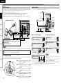
n Positioning the Antenna
For a consistent satellite signal, the antenna must be positioned correctly. Use the following map to
determine which area you are in and position the antenna accordingly.
q
w
e
r
t
SOUTH
NORTH
WEST
SKY
EAST
HORIZON
Area 1 : Point the antenna toward the sky in the east,
northeast, or southeast, either through a
window or outside.
Area 2 : Point the antenna toward the sky in the north
or northeast, either through a window or
outside.
Area 3 : Point the antenna toward the sky in the north
or northwest, either through a window or
outside.
Area 4 : Point the antenna toward the sky in the west,
northwest, or southwest, either through a
window or outside.
Area 5 : Put the antenna outside and point it straight
up. The antenna cannot be used indoors.
b When connecting
digital audio
Direction of broadcasting station
AM loop
antenna
(supplied)
FM antenna
75 Ω/ohms
Coaxial cable
FM indoor antenna
(supplied)
Ground
AM outdoor antenna
Antenna terminals
n AM loop antenna assembly
1
Remove the vinyl tie and take
out the connection line.
2
Bend in the reverse direction.
3
With the antenna
on top of any
stable surface.
3
With the antenna
attached to a wall.
-1
-2
Mount
Installation hole Mount on wall, etc.
1
Push the lever.
2
Insert the conductor.
3
Return the lever.
n Connection of AM antennas
NOTE
• Do not connect two FM antennas
simultaneously.
• Even if an external AM antenna is used, do not
disconnect the AM loop antenna.
• Make sure the AM loop antenna lead terminals do
not touch metal parts of the panel.
Set this to change the input signal to which the input
source is assigned.
“Input Assign” (vpage 35)
Set as necessary
Connections
Page is loading ...
Page is loading ...
Page is loading ...
Page is loading ...
Page is loading ...
Page is loading ...
Page is loading ...
Page is loading ...
Page is loading ...
Page is loading ...
Page is loading ...
Page is loading ...
Page is loading ...
Page is loading ...
Page is loading ...
Page is loading ...
Page is loading ...
Page is loading ...
Page is loading ...
Page is loading ...
Page is loading ...
Page is loading ...
Page is loading ...
Page is loading ...
Page is loading ...
Page is loading ...
Page is loading ...
Page is loading ...
Page is loading ...
Page is loading ...
Page is loading ...
Page is loading ...
Page is loading ...
Page is loading ...
Page is loading ...
Page is loading ...
Page is loading ...
Page is loading ...
Page is loading ...
Page is loading ...
Page is loading ...
Page is loading ...
Page is loading ...
Page is loading ...
Page is loading ...
Page is loading ...
Page is loading ...
Page is loading ...
Page is loading ...
Page is loading ...
Page is loading ...
Page is loading ...
Page is loading ...
Page is loading ...
Page is loading ...
Page is loading ...
-
 1
1
-
 2
2
-
 3
3
-
 4
4
-
 5
5
-
 6
6
-
 7
7
-
 8
8
-
 9
9
-
 10
10
-
 11
11
-
 12
12
-
 13
13
-
 14
14
-
 15
15
-
 16
16
-
 17
17
-
 18
18
-
 19
19
-
 20
20
-
 21
21
-
 22
22
-
 23
23
-
 24
24
-
 25
25
-
 26
26
-
 27
27
-
 28
28
-
 29
29
-
 30
30
-
 31
31
-
 32
32
-
 33
33
-
 34
34
-
 35
35
-
 36
36
-
 37
37
-
 38
38
-
 39
39
-
 40
40
-
 41
41
-
 42
42
-
 43
43
-
 44
44
-
 45
45
-
 46
46
-
 47
47
-
 48
48
-
 49
49
-
 50
50
-
 51
51
-
 52
52
-
 53
53
-
 54
54
-
 55
55
-
 56
56
-
 57
57
-
 58
58
-
 59
59
-
 60
60
-
 61
61
-
 62
62
-
 63
63
-
 64
64
-
 65
65
-
 66
66
-
 67
67
-
 68
68
-
 69
69
-
 70
70
-
 71
71
-
 72
72
-
 73
73
-
 74
74
-
 75
75
-
 76
76


Ask a question and I''ll find the answer in the document
Finding information in a document is now easier with AI
Related papers
-
Denon AVR-988 Owner's manual
-
Denon AVR-1910 User manual
-
Denon Home Theater System AVR-2310CI User manual
-
-
Denon AVR-790 Owner's manual
-
Denon AVR-590 User manual
-
-
-
-
Other documents
-
Marantz SR7007 Owner's manual
-
Sony SLV-D500 Dimensions
-
-
Epson AVR-687 User manual
-
Marantz PM6005 User manual
-
Yamaha RX-V1900 User manual
-
Yamaha HTR-6260 User manual
-
Yamaha V665 - RX AV Receiver Owner's manual
-
-
Marantz PM8005 Owner's manual